Official URL
https://doi.org/10.1109/IWCMC.2017.7986274
Any correspondence concerning this service should be sent
to the repository administrator:
[email protected]
This is an author’s version published in:
http://oatao.univ-toulouse.fr/22061
Open Archive Toulouse Archive Ouverte
OATAO is an open access repository that collects the work of Toulouse
researchers and makes it freely available over the web where possible
To cite this version: Elloumi, Mouna and Escrig, Benoît and
Dhaou, Riadh and Idoudi, Hanen and Azzouz Saidane, Leila
Designing an energy efficient UAV tracking algorithm. (2017) In:
13th International Wireless Communications & Mobile Computing
Conference, Workshop on Multihop Wireless Network Testbeds
and Experiments (IWCMC 2017), 29 June 2017 - 30 June 2017
(Valence, Spain).
Designing an energy efficient UAV tracking
algorithm
Mouna Elloumi*, Benoit Escrig*, Riadh Dhaou*, Hanen Idoudi**, Leila Azouz Saidane** *University of Toulouse, IRIT-ENSEEIHT, Toulouse, France
**University of Manouba, CRISTAL-ENSI, Manouba, Tunisia
*E-mail: [email protected], {Benoit.Escrig, Riadh.Dhaou}@enseeiht.fr **E-mail:{hanen.idoudi, leila.saidane}@ensi.rnu.tn
Abstract—In this paper, we present a solution for Unmanned Aerial Vehicle (UAV) energy saving problem while ensuring a continuous tracking of a mobile target. Our tracking algorithm is based on three zones, and according to the target placement in those zones, the UAV will do a specific type of actions. We proposed an additional zone called the authorized zone. In this zone, the UAV keeps a fixed velocity and a fixed altitude, and this contributes to the limitation of the energy consumption while also maintaining a minimal altitude. We also proposed an adapted criterion which considers the velocity, altitude and acceleration changes to evaluate the energy consumption. The idea here is to limit the number of the UAV adjustments to reduce the energy consumption and still keeping the target in its camera field of view.
Keywords: Unmanned Aerial Vehicle (UAV), mobile target, tracking, camera field of view, energy consumption.
I. INTRODUCTION
Unmanned Aerial Vehicles (UAVs) are increasingly used in civil applications after being used in military applications. Examples of civil applications are entertainment, environment, agriculture, and disaster management [1].
In this paper, we focus on a challenging issue that is receiving more attention than ever: Mobile target tracking. The challenges of such mission is the transmission of target images in real time, tracking correctly the target, and saving the UAV energy. Visual tracking is applied in many situations, such as search and rescue missions [2], and cars tracking to monitor the vehicular traffic [3].
In the tracking process there is two phases. The first phase of this process is the transient phase, and it is identified by the UAV taking off and starts localizing the mobile target. When the first phase is accomplished, the UAV start doing adjustments to keep the target in its field of view, this second phase is called the steady phase. Several tracking approaches considered both transient and steady phases. In [4], multiple UAVs are collaborating to localize a single target and track it. In the transient phase, the UAV localizes as fast as possible the target. While in the steady phase, the UAV tries to keep the target in its center of view, by updating its position based on the previous one and on the two last target positions errors. In [5], both phases were also considered. In the transient phase, the UAV reaches a desired altitude using a certain strategy. For the steady phase a strategy was developed as well. This
strategy aims to keep the target in the UAV field of view center, so either the UAV aligns its position with the target position or increases its altitude to get a better view of the scene. There are already many contributions done in the transient phase. For instance, minimizing the duration of this phase and minimizing the energy consumption. While for the steady phase the energy efficiency problem was almost not addressed. That is why we consider only the steady phase, we assume that initially the target is in the field of view of the UAV, indeed we do not consider the takeoff and the landing phases. Trying to keep the target exactly in the center of the field of view with no authorized space where the target still can be tracked correctly can cause two limitations: unnecessary adjustments, leading to additional needless energy consumption and limiting the possibility to track multiple targets.
In [6], a fixed wings UAV is tracking a target by doing circular movements. The objective is to generate an optimal path for the UAV when it is tracking a stationary target or when the target velocity is lower than the minimum velocity of the UAV. We do not deal with those two scenarios as we choose to work with a rotary wings UAV with less operational and physical constraints.
In tracking applications, there is also the coverage issue. With a single target this problem is not raised, but with multiple targets same solutions assume a continuous coverage of the tracking area. In [7], multiple UAVs cooperate to track multiple targets. So a strategy was developed to enable each UAV to track a group of target with an optimal pose and to generate conflict-free paths for all UAVs. In [8], several UAVs track several targets. The goal is to save energy while ensuring a continuous coverage. During the tracking only the altitude is adapted and kept as low as possible. However, there is a need to optimize the number of drones while keeping a continuous coverage. Ensuring a continuous coverage is questionable, especially for low targets density, and it raises the problem of UAV placement and replacement.
Ensuring a correct and a stable tacking, i.e., the targets are in the field of view (FoV) of the UAVs cameras, is not the only issue. The issue of UAV energy consumption must be addressed as well. Because this problem is very complex, we start dealing with a single UAV tracking a single mobile target. The main contribution of this paper is the proposal of a
tracking algorithm for a single UAV and a single mobile target. In this algorithm we define three zones, and according to the position of the target in those zones, the UAV does different types of adjustments and less frequently, allowing to reduce the consumed energy.
The rest of the paper is organized as follows. Section II develops our tracking approach. In section III, we present our tracking algorithm for a single UAV and our approach to compute the dissipated energy. In Section IV, we analyze our simulation results. We conclude in Section V.
II. SYSTEMMODEL
In this section, we present the UAV type and our tracking approach.
A. UAV type
For simulations, we have the choice between a fixed wings UAV or rotary wings UAV. Authors in [9] [10] [6] used fixed wings UAVs. Authors in [4] [5] used rotary wings UAVs. Rotary wings UAVs are chosen because they land and take off vertically and maintain a null speed. They are suitable when the target is stationary for a period of time, because they can maintain a null speed and still flying. While the fixed wings UAVs require a certain motion planning (circular movements) to persistently track the target because of their operational and physical constraints.
B. Tracking approach
The steps of tracking a mobile object are the detection of the target which means extracting the target from the images backgrounds, target states estimation (velocity and position), and the adjustment of the UAV placement to keep the mobile target in its field of view (FoV).
1) Target detection: in a target tracking mission, the first task consists of detecting the presence of the target in the field of view of the UAV camera. This step can be performed by comparing the correlation between the target image and target template to a detection threshold. This issue is beyond the scope of the paper, we assume that the detection of the target is error free.
2) Target states estimation: because we got complex and dynamic trajectories with changes of acceleration, we cannot use linear systems to model those trajectories [11]. That is why for the target state estimation step we use an extended Kalman filter (EKF) like in [7] because it is adapted to a nonlinear system.
EKF is a predictor-corrector algorithm. First, the current state is predicted according to the previous state. Then mea-surements are associated with states, and finally the predictions are corrected using measurements.
The system model equations are:
x(k) = f [x(k − 1)] + w(k − 1) (1) z(k) = h[x(k)] + v(k) (2) The equation (1) is the state equation used to predict the state.
The equation (2) is the measurement equation used in our application to extract the position. The time axis is divided into time-slots, and they are called frames. The state vector is denoted x(k) (positions and velocity), z(k) is the measured position vector, f [x(k)] is a function that predicts the state in framek + 1 according to the state in frame k, h[x(k)] is a function that associates measurements to the state vectors. The noise processesw(k) and v(k) are Gaussian independent processes with diagonal covariance matrices with varianceσ2 w andσ2
vrespectively. These two processes are modeling system and detection errors respectively.
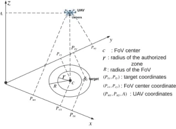
3) Target tracking: the innovation in our approach is ensur-ing not only a correct trackensur-ing of the target but also reducensur-ing the energy consumption of the UAV. That is why we define three zones: authorized zone, correction zone, and re-detection zone. Fig. 1 introduces the three zones. The center of the three zones is represented by c, r is the radius of the authorized zone, the zone betweenr and the radius of the camera FoV R is the correction zone, and the re-detection zone is the zone outside the camera FoV. The value ofR is computed by using the following expression.
R = (A × θ)
2 × CST (3)
whereA is the altitude of the UAV, θ is the camera angle and CST is a constant equal to 57.3. The bigger the angle, the biggerR, and the higher the altitude, the bigger R.
By defining those three zones the UAV will consume less energy because it will do less frequent adjustments, indeed in each zone the UAV does specifics adaptation actions. If the target is in the authorized zone, the UAV does not change its altitude or its velocity. If the target is the correction zone, the UAV only corrects its velocity and position. In the re-detection zone, i.e., when the target is out of the FoV, the UAV adjusts its velocity, position, and its altitude to get a larger view of the scene to detect the mobile object once again. Also in our approach we maintain a minimal altitude of the UAV before and after the adjustments to reduce the energy consumption.
III. TRACKING ALGORITHM
This section presents our tracking algorithm for a single UAV and a single target and our approach to compute the energy dissipated in UAVs.
A. Tracking algorithm for a single UAV and a single target
Algorithm 1 shows how the UAV reacts considering the target position.
In this algorithm, during the simulation time Tmax if the distance d between the estimated position of the target and the position of the UAV FoV center is lower than r, the UAV will keep its same previous velocity (Vux,Vuy). Ifd is betweenr and R, the UAV will update its current velocity and position (Pux,Puy) with the estimated values of target velocity (Vtx,Vty) and position (Ptx,Pty). Finally, ifd is higher than R, the UAV will update its current velocity, position, and altitude A. The updated altitude An is the altitude allowing the UAV
Fig. 1: The adjustment areas
to have the target in its FoV again. ESTIMATION refers to the function that estimates the position and velocity of the target by using EKF.
Algorithm 1: tracking a target using one UAV
Input:r, R, A, d, (Ptx,Pty) estimated target position, (P realtx,P realty) real target position, (Pux,Puy), (Vux,Vuy), (Vtx,Vty) estimated target velocity coordinates,Tmax,An UAV adapted altitude, Aminminimal UAV altitude,T time between two measurements 1 fori = 1 to Tmax do 2 (Ptx,Pty,Vtx,Vty) = ESTIMATION (P realtx, P realty) 3 ifd < r then 4 (Vux(i), Vuy(i)) ← (Vux(i − 1), Vuy(i − 1)) (Pux(i), Puy(i)) ←
(Pux(i−1)+T ×Vux(i), Puy(i−1)+T ×Vuy(i)) 5 end
6 ifr ≤ d ≤ R then
7 (Vux(i), Vuy(i)) ← (Vtx(i), Vty(i)) (Pux(i), Puy(i)) ← (Ptx(i), Pty(i)) 8 end
9 ifd > R then 10 A(i) ← An(i)
11 (Vux(i), Vuy(i)) ← (Vtx(i), Vty(i)) (Pux(i), Puy(i)) ← (Ptx(i), Pty(i)) 12 A(i) ← Amin
13 end 14 end
We assume that the maximal velocity of the target is lower than the maximal velocity of the UAV.
B. Energy consumption
An UAV system can be modeled with several power con-sumer components [12]. The components are the communi-cation, the motors, the control, the data processing, and the
internal and external load. The communication component involves sending or receiving control commands, data or updating information. The motors component will consume more energy when the UAV increases its altitude, accelerates or decelerates. The control component includes sensors and detectors. In the data processing component, running algo-rithms such as detection and localization will consume energy. An example of internal load is electrical motors which cause some energy losses due to their operating temperatures. An example of external loads is weather conditions.
For the energy part, we are only interested in the energy consumed due to movements and communication. Because the energy consumption of the other components is the same in all scenarios.
1) Transmission energy consumption: first, we compute the dissipated energy when sending compressed images to the base station [13].
E = Eo+ Ea+ Mt× Et (4)
whereEois the energy dissipated by the local oscillator which generates the required carrier frequency, Ea is the energy dissipated by the power amplifier which amplifies the signal to produce the required RF transmit power Pt, Et is the energy dissipated by the transmitter which is responsible of modulation and up-conversion (translating the baseband signal to RF),Mtis the size of the messages to transmit. We assume that the transmission powerPt is always maximal and equal to 20 dbm.
2) Movement energy consumption: we compute the move-ments energy consumption in the three possible phases (cruis-ing, increasing altitude and decreasing altitude) [14] [15] [16]. The energy is computed every second, soT which is the time between two measurements is equal to 1 sec.
a) Cruising:
E1= P1× T + m × a × V × T (5) whereE1 is the energy dissipated in the cruise phase, m is the weight of the UAV,a is the acceleration or deceleration, V is the velocity, P1is a constantly consumed energy in the cruise phase equal to 80 Joules.
b) Increasing altitude:
E2= P2× T + m × g × h × T + E1 (6) where E2 is the energy dissipated when increasing altitude, g is the gravitational constant, h is the UAV altitude, P2 is a constantly consumed energy in the changing altitude phase equal to 110 Joules.
c) Decreasing altitude:
E3= m × g × h × T + E1 (7) whereE3is the energy dissipated when decreasing altitude
IV. SIMULATION
In this section, we evaluate the performance of the proposed algorithm in terms of correct tracking and reduction of UAV energy consumption.
A. Simulation Parameters
MATLAB is used for simulation purposes. The measure-ments are done every second. The simulation parameters are presented in table I and table II.
TABLE I: Simulation parameters for the tracking algorithm
Parameters Value Unit
Maximal velocity of the UAV (V max) 200 m/s Minimal velocity of the UAV (V min) 0 m/s Maximal altitude of the UAV (Amax) 200 m Minimal altitude of the UAV (Amin) 60 m Initial UAV and target positions (0, 4) m Initial UAV and target velocities (0, 5) m/s
θ 50 deg
Radiusr R/3 m
σ2w 0.5
σ2
v 1
Simulation time 60 sec
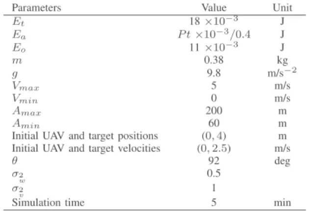
TABLE II: Simulation parameters for the energy computation
Parameters Value Unit
Et 18 ×10−3 J Ea P t ×10−3/0.4 J Eo 11 ×10−3 J m 0.38 kg g 9.8 m/s−2 Vmax 5 m/s Vmin 0 m/s Amax 200 m Amin 60 m
Initial UAV and target positions (0, 4) m Initial UAV and target velocities (0, 2.5) m/s
θ 92 deg σ2 w 0.5 σ2 v 1
Simulation time 5 min
For the energy part, we use the parameters of Ar.Drone version 2.0 to get realistic observations. The battery type is Lithium polymer.
B. Simulation Results
1) Tracking algorithm for a single target and a single UAV:
the movements to study are rectilinear with a constant velocity, rectilinear with variable velocity, nonrectilinear with a constant velocity, and nonrectilinear with variable velocity. We use nonrealistic target movement to observe how the UAV respond. For all scenarios, we assume that the UAV is in the cruising phase, i.e., we do not consider the takeoff and landing phases.
a) The target moves in a straight line with a fixed velocity: by testing this scenario we are making sure that there is no estimation and tracking errors.
Fig. 2: distance between the target and the UAV FoV center
b) The target moves in a straight line with a variable velocity: in Fig. 2 we observe when the different UAVs adaptation occurs. The adaptation of the altitude occurs four times (at the seconds 9, 52, 56 and 58) due to the overrun ofR. The adjustment of the speed and position occurs at the seconds 11, 13, 16, 18, 20, 23 and 54 because the estimated values are between r and R. When the estimated values of distance are lower thanr, the UAV does not adjust its speed.
c) The target moves in a nonstraight line with a constant velocity: this scenario is not realistic because it is not possible to change direction while keeping the same velocity.
Fig. 3: Distance between the target and the UAV FoV center When the target only changes its direction, it does not go out from the UAV FoV. In this scenario the estimated distance exceedsr nine times, one second later, this distance becomes equal to zero because of the adjustment done in the corrections zone (Fig. 3).
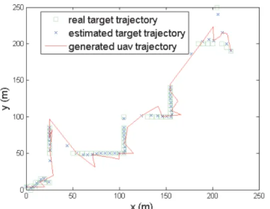
d) The target moves in a nonstraight line with a variable velocity: since this scenario is the combination of the last two ones, we deduce that the error of position estimation is due to velocity changes. For example, from Fig. 4, at the second 19 the actual position is(50m, 50m) while the estimated position is (43.7m, 59.9m). Estimations are different from the real values. Also, the generated values of the UAV does not always
Fig. 4: UAV and target trajectories
coincide with the estimated values of the target because of the adjustments that differ from one area to another.
e) Extreme cases: when the velocity of the target exceeds the velocity of the UAV, the UAV reaches its maximal altitude and maximal velocity. So for sure the algorithm continues running.
2) Energy consumption: in the previous section we vali-dated our tracking algorithm. Now we confirm its effective-ness in minimizing the energy consumed by UAVs motors compared to other algorithms.
To compute the radius of each zone we vary the r/R proportion from 0.1 to 0.9 and we choose the proportion that gives the best results in term of energy left in the UAV battery and in term of distance between the target and the UAV FoV center. So in Fig. 5, we compute for each r/R the energy left and the average distance between the target and the FoV center for5min of simulation.
From Fig. 5(a), we conclude that forr = 2 × R/3 the UAV consumes less energy but the distance between the target and the FoV center is greater than for the other proportions (Fig. 5(b)). The r = R/3 and r = R/4 proportions are the best choices because the energy consumption is almost the same as in r = 2 × R/3 and the average distance is less than one meter.
Also to choose the altitude a compromise must be found between the image quality, the motor energy consumption, and the communication energy consumption. The higher the altitude, the higher the power needed to transmit images. Since we always transmit at the highest power, the altitude will not have an effect on the communication energy consumption. Because sending high images quality is our priority, we fix the altitude before and after adaptation to the minimal possible which is60m. Also with a lower UAV altitude, the target will be defined with a larger number of pixel, so the probability to detect it will be higher.
In other approaches, there are only two zones: inside and outside the FoV with two alternatives. The first alternative consists of always doing the position and velocity corrections when the target is still inside the FoV. The second consists of
(a) The energy left of the UAV battery
(b) The average distance between the target and the FoV center
Fig. 5: Impact ofr/R on motor energy consumption and on the distance between the target and the FoV center
correcting the UAV placement and velocity only if the target is outside the FoV [5].
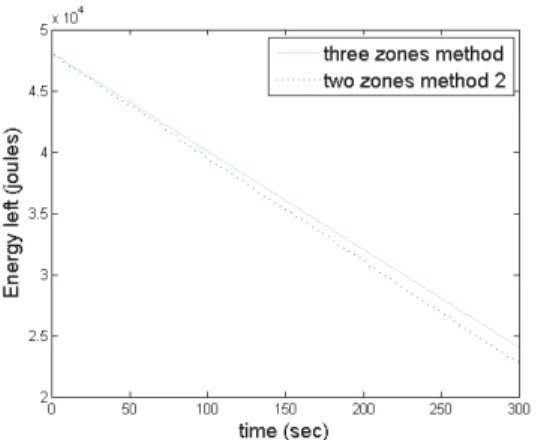
To compute the energy consumption, we run simulations for 5 minutes to get more accurate estimations. Initially, the battery capacity is 47952 J.
In Fig. 6, we compare our method (three zones method) to the method where adjustments are always done (two zones method 1), and to the method where adjustments are done only if the target is out of the UAV FoV (two zones method 2). We observe less energy consumption in our method. We did the simulation when the movement of the target is rectilinear with a variable velocity (Fig. 6(a)), and when it is non rectilinear with a variable velocity (Fig. 6(b)).
For the communication energy part, if the size of the images to transmit is 5Mbit, the battery will be discharged of 0,10 %. This percentage can go up to 1,17 % if the size of images is 100Mbit. For the motor energy consumption, the battery will be discharged around 50 %. So we conclude that the energy consumption due to communication is negligible compared to the one consumed by motors.
(a) The energy left of the UAV battery for a rectilinear movement with a variable velocity
(b) The energy left of the UAV battery for a non rectilinear movement with a variable velocity
Fig. 6: Comparison of the UAV energy dissipation
V. CONCLUSION AND FUTURE WORK
In this paper, we proposed a tracking algorithm for a single UAV based on three zones. We computed the energy consumption caused by transmitting images and by vertical and horizontal UAV movements. Finally, simulations showed a successful tracking, a less energy consumption compared to other approaches. Also, simulations showed that the energy consumption due to communication is negligible compared to the energy consumed because of movements.
For future work, we will concentrate on scenarios with multiple targets and multiple UAVs. We will study the com-munication, the cooperation and the resource sharing between UAVs using the LTE technology.
REFERENCES
[1] J. Villasenor, “drones and the future of domestic aviation [point of view],” Proceedings of the IEEE, vol. 102, no. 3, pp. 235–238, 2014.
[2] L. Apvrille, T. Tanzi, and J.-L. Dugelay, “Autonomous drones for assisting rescue services within the context of natural disasters,” in General Assembly and Scientific
Symposium (URSI GASS), 2014 XXXIth URSI, pp. 1–4, IEEE, 2014.
[3] F. Heintz, P. Rudol, and P. Doherty, “From images to traffic behavior-a uav tracking and monitoring applica-tion,” in Information Fusion, 2007 10th International
Conference on, pp. 1–8, IEEE, 2007.
[4] M. A. Ma’sum, G. Jati, M. K. Arrofi, A. Wibowo, P. Mursanto, and W. Jatmiko, “Autonomous quadcopter swarm robots for object localization and tracking,” in
Micro-NanoMechatronics and Human Science (MHS), 2013 International Symposium on, pp. 1–6, IEEE, 2013. [5] J.-E. Gomez-Balderas, G. Flores, L. G. Carrillo, and R. Lozano, “Tracking a ground moving target with a quadrotor using switching control,” Journal of Intelligent
& Robotic Systems, vol. 70, no. 1-4, pp. 65–78, 2013. [6] Z. He, J.-X. Xu, S. Yang, Q. Ren, and X. Deng, “On
trackability of a moving target by fixed-wing uav using geometric approach,” in Industrial Electronics (ISIE),
2014 IEEE 23rd International Symposium on, pp. 1572– 1577, IEEE, 2014.
[7] N. Farmani, L. Sun, and D. Pack, “Tracking multiple mobile targets using cooperative unmanned aerial ve-hicles,” in Unmanned Aircraft Systems (ICUAS), 2015
International Conference on, pp. 395–400, IEEE, 2015. [8] D. Zorbas, T. Razafindralambo, F. Guerriero, et al.,
“En-ergy efficient mobile target tracking using flying drones,”
Procedia Computer Science, vol. 19, pp. 80–87, 2013. [9] X. Wang, H. Zhu, D. Zhang, D. Zhou, and X. Wang,
“Vision-based detection and tracking of a mobile ground target using a fixed-wing uav,” International Journal of
Advanced Robotic Systems, vol. 11, 2014.
[10] A. Qadir, W. Semke, and J. Neubert, “Implementation of an onboard visual tracking system with small unmanned aerial vehicle (uav),” arXiv preprint arXiv:1205.5742, 2012.
[11] E. V. Cuevas, D. Zaldivar, and R. Rojas, “Kalman filter for vision tracking,” 2005.
[12] B. Uragun, “Energy efficiency for unmanned aerial vehi-cles,” in Machine Learning and Applications and
Work-shops (ICMLA), 2011 10th International Conference on, vol. 2, pp. 316–320, IEEE, 2011.
[13] A. Y. Wang and C. G. Sodini, “On the energy ef-ficiency of wireless transceivers,” in Communications,
2006. ICC’06. IEEE International Conference on, vol. 8, pp. 3783–3788, IEEE, 2006.
[14] C. Beaverstock, R. Ajaj, M. Friswell, R. De Breuker, and N. Werter, “Optimising mission performance for a mor-phing mav,” in Proceedings of the Ankara International
Aerospace Conference, Ankara, Turkey, vol. 1113, 2013. [15] M. Hepperle, “Electric flight-potential and limitations,”
2012.
[16] H. M. G. Vidales, “Design, construction and test of the propulsion system of a solar uav,” MSc, Aerospace