To link to this article:
DOI:10.1016/j.compositesb.2016.11.003
URL:
http://dx.doi.org/10.1016/j.compositesb.2016.11.003
This is an author-deposited version published in:
http://oatao.univ-toulouse.fr/
Eprints ID: 19724
To cite this version:
Omrani, Fatma and Peng, Wang and Damien, Soulat and Ferreira,
Manuela and Ouagne, Pierre Analysis of the deformability of flax-fibre
nonwoven fabrics during manufacturing. (2017) Composites Part B:
Engineering, vol. 116. pp. 471-485. ISSN 1359-8368
O
pen
A
rchive
T
oulouse
A
rchive
O
uverte (
OATAO
)
OATAO is an open access repository that collects the work of Toulouse researchers and
makes it freely available over the web where possible.
Any correspondence concerning this service should be sent to the repository
administrator:
[email protected]
Analysis of the deformability of flax-fibre nonwoven fabrics during
manufacturing
Fatma Omrani
a, Peng Wang
a,*, Damien Soulat
a, Manuela Ferreira
a, Pierre Ouagne
baUniversity of Lille, ENSAIT, GEMTEX, F-59056 Roubaix, France
bENI Tarbes, LGP, F-65016 Tarbes, France
Keywords: A. Fabrics/textiles E. Forming Natural fibre Nonwoven fabrics Characterization
a b s t r a c t
The use of natural fibres for technical advanced products such as composites is widely increasing with the view to reduce the impact of the material throughout its life cycle on the environment. Some work has been performed on natural fibre based reinforcement textiles for composite materials. The me-chanical and the formability behaviours of woven fabrics has particularly been characterised. However, few research work concerns the forming aptitude of nonwoven fabrics despite promising preliminary studies. In the present work, the mechanical characterizations of flax-fibre nonwoven reinforcements are carried out firstly. Then the forming tests of the nonwoven fabrics are performed to quantify their formability behaviour. The tensile and forming tests showed very different mechanical behaviours in comparison to the ones observed on woven fabrics due to the non-uniformity of nonwoven fabric. The high deformation potential of the nonwoven fabrics is established. The specific behaviour of the nonwoven fabrics is studied by analysing the local and global deformation mechanisms of the rein-forcement during forming. Moreover, the manufacturing defects experienced in nonwoven fabric forming are demonstrated. The slippage/damage of network is a typical problem in the nonwoven fabric forming, which depends strongly on the fibre density (area density) of fabric and blank-holder pressure.
1. Introduction
According to INDA (the North American Association of the Nonwoven Fabrics Industry) “nonwoven fabrics are broadly defined as sheet or web structures bonded together by entangling fibre or filaments (and by perforating films) mechanically, thermally or chemically. They are not made by weaving or knitting and do not require converting the fibres to yarn[1]. Nonwoven fabrics are used in the automotive industry for a variety of applications due to their lightweight, sound efficiency, flexibility, versatility and easy tailored properties, low process and materials costs as well as an attractive cost/performance ratio[2,3]. They are playing a key role in the automotive market. They can be found in cabin air filters, in moulded seat coverings, headliners, trunk liners and carpeting[4]. They can also provide interesting properties as lining materials because of their ease of handling, their shape adaptability charac-terised by a high formability potential[5e9]. Such materials can be manufactured by bonding together fibres or bundles to create a
nonwoven network.
Nonwoven fabrics are manufactured in one continuous process directly from the raw material to the finished fabric[10]. This is particularly interesting to minimise the production cost and the impact on the environment[11]. Because of the low mechanical properties of composites manufactured from random nonwoven mats, researchers in recent years have been looking for highly aligned, yarn-based natural fibre reinforcement structures for the manufacture of composite components in load-bearing applica-tions[12]. Miao et al. [12]compared, in the case of natural fibre based materials, the mechanical properties of thermoplastic com-posites elaborated from un-oriented fibres to the ones from aligned fibre yarns. By using an Ashby method, Shah[13]recently proved that the absolute and specific tensile properties of PFRP (plant fibre reinforced plastics) manufactured using nonwoven fabrics are globally 2 to 20 times lower than unidirectional reinforcement based composites. However, the ones elaborated from nonwoven based fabrics outperform unidirectional and multiaxial PFRPs in terms of property per unit cost. If all these studies mainly deal with the tensile mechanical behaviour of composites manufactured from nonwoven reinforcements, the identification of the mechanical properties of dried nonwoven preform has not been widely studied * Corresponding author.
[14]. Experimental analysis conducted by Farukh et al. [14,15]
showed significant tensile strain abilities in the 50% range. They also showed that strong anisotropy in mechanical property could be observed because of the non-uniform orientation distribution of the fibres within the nonwoven structure. High deformability properties which are an advantage during manufacturing processes of composite materials may therefore be observed as a conse-quence of the large tensile strain abilities of the nonwoven fabric.
Resin Transfer Moulding (RTM) [16] is one of the main manufacturing process to produce composite parts for the trans-port industries[17,18]. A lot of experimental[19e26]and numerical
[27e32]studies concerning the draping stage of dry reinforcement, the first step of RTM process, were carried out to analyse the deformability of different reinforcements on more and more complex shapes. Many studies have been conducted about the preforming of carbon, glass and also natural fibre textiles in woven fabrics[20,21,25,33,34], Non-Crimp- Fabrics[35e37], 3D interlock
[38], weft-knitted fabric [39], and more recently braided re-inforcements[40]were considered. However, the deformability of nonwoven reinforcements during the preforming step was not studied on the contrary to the resin flow characteristics (perme-ability) of natural fibre nonwoven during the injection step
[41e43]. The behaviour of highly aligned reinforcements (woven, braided knitted, etc…) during the preforming step is characterised by complex coupled tensile, in-plane shear, bending but also and compaction deformations[28]. Criteria to define the feasibility to realize a particular shape are based on limits of these deformations, such as the locking angle[28,44,45]for the in-plane shear behav-iour. Because of their manufacturing processes leading to a non-uniform orientation distribution of their fibres, the anisotropy and non-uniformity of nonwovens cannot be avoided. Conse-quently, the definition of criteria characterising the deformability during the preforming stage cannot be the same to the ones of highly aligned reinforcements. This study is dedicated to an experimental approach on the deformability of dried natural fibre nonwovens on a preforming device. A punch and die system was used to form hemispherical geometry and also a more complex square shape.
2. Materials and methods
Flax tows (Linum usitatissimum L. from the Normandy area of France) were used as reinforcement fibres in the nonwoven. The description of the fibres is presented inTable 1. The industrial flax-fibre nonwoven was manufactured according to the carding/over-lapping/needle punching technology [4] by EcoTechnilin SAS in France under its commercial name Fibrimat. Two nonwoven re-inforcements with the areal densities of 300 g/m2 (F300) and 450 g/m2 (F450) are considered in this work. F300 and F450 share the same manufacturing process. A dry process involving carding during which the fibres are bound together and parallelized in the machine direction to form a batt is used before undergoing bonding by the needling process. The main properties of the flax-fibre nonwoven preforms are given inTable 2. The areal density and the thickness of nonwoven were measured according to the stan-dard methods ISO 3616 and ISO 9073 respectively. It can be noted
that the standard deviation of the areal density is relatively high (10%) and is due to the non-homogeneity of both fabrics.
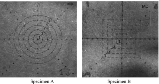
The mechanical characterization of nonwoven fabric in both Machine and Cross directions (MD and CD) was performed in this work. During the tensile test, it was observed that the specimen did not deform homogenously. Large local area density variations can be observed during the test. Consequently associated to global mechanical responses, it is necessary to perform more local anal-ysis. Ten local zones are defined to analyse the evolution of their surfaces during the tensile tests as shown inFig. 1. Five symmetric up and below zones are defined on each test specimen. Each zone has the same initial surface area. Each test according to the ISO 13934-1 test method was repeated seven times. The crosshead speed used during the tensile test is 100 mm/min and the di-mensions of the sample are 200 ! 50 mm2.
In order to investigate the formability behaviour of nonwoven fabrics during manufacturing, test specimens were prepared. The tested plies were cut in MD and CD (0/90"ply) and also in MDþ45" and CDþ45"directions (±45"ply). The surface dimensions of the specimens are 250 ! 250 mm2. A mark tracking technique was used to monitor the local deformations of the preform during the forming. The positions of the markers points are presented inFig. 2. These markers are placed from the centre of the reinforcement to the edges every 15 mm. A video camera installed on the forming device is used to measure the evolution of the markers position.
Table 1
Description of the flax fibres.
Reinforcing fibre Flax
Origin France
Average fibre length (mm) 80
Density (g/cm3) 1.45
Colour Natural
Table 2
The main properties of the flax-fibre reinforced nonwoven fabrics.
Nonwoven fabric F300 F450
Manufacturer EcoTechnilin (France)
Production method Carding/Needling Carding/Needling Area density (g/m2) 300 (±30) 450 (±45) Thickness (mm) (pressure 1 KPa) 2.50 (±0.02) 3.52 (±0.37)
Local zones are defined on the specimens. The evolution of local area density can be performed during forming. Two different preparations of specimen are shown inFig. 2with round (specimen A) or square (specimen B) zones, depending on the shape of the tools (hemi sphere for specimen A and square box for specimen B). The initial surface (S0) of each zone is shown inTable 3.
As the change of environment humidity may strongly influence the deformability behaviour of the nonwoven fabric because of the modification of the friction behaviour between the tool and the fabric[46], the samples were dried in an oven at 60"C for 30 min before being rapidly tested on the forming device. The forming stage is very rapid (within the range of 15 s), consequently the modification of friction between the tools and the fabric due to the change of environment humidity can be negligible during forming tests.
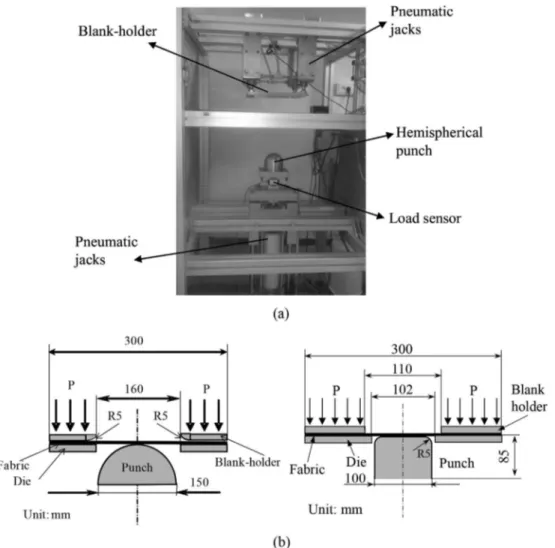
Preforming tests of nonwoven fabrics were performed on a specific sheet forming device shown inFig. 3a[38]. This device was designed to analyse the deformability of the double-curved shape manufacturing with a given textile reinforcement under different forming conditions (shape and size of punch, position and pressure of blank-holder …). The given flax-fibre nonwoven fabric was placed between the blank-holder and die (Fig. 3b). Two types of punch were used in this study: the hemispherical and square box punches as described onFig. 3b. Four pneumatic jacks, connected to the blank-holder, apply an adjustable pressure on the fabric. A low (0.01 MPa) and high pressure (0.2 MPa) were used in forming tests. In order to measure the evolution of local area density and monitor the forming defects by optical measurement, the “open-die” forming system is proposed. Another electric jack imposes the punch displacement. The punch displacement in hemispherical and square box forming tests was respectively 65 mm and 80 mm. A load sensor measures the punch force during the forming.
3. Results
3.1. Characterization of the tensile behaviour of flax-fibre nonwoven fabrics
3.1.1. Global scale
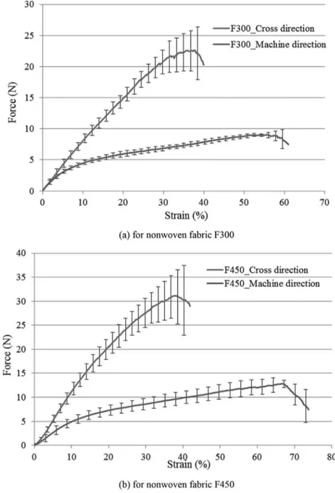
The evolution of the tensile force as a function of the strain applied to the nonwoven fabrics in CD and MD are shown inFig. 4. The tensile behaviour is characterised by large strains and anisot-ropy, as described by Farukh et al.[14,15]. It can be noted that a higher effort and a smaller deformation are observed in both cases at the maximum load point in CD than in MD. The cohesion be-tween the fibres is larger in the CD than in the MD. This can be understood by the fact that more friction due to higher entangle-ment between the fibres and bundles takes place in the CD than in the MD where the fibres are globally aligned during the fabrication process. The global tensile stiffness of the two reinforcements is presented inTable 4. The stiffness ratio for both materials between the CD and the MD is equal to 1.3. This therefore confirms the global anisotropy of the reinforcements. One can also observe that the F450 fabric is more rigid in both cross and machine directions than the F300 one. A ratio of 1.5 has been calculated between the property measured from the F450 and the F300 and that for both machine and cross directions. These last results therefore show that the global stiffness properties are directly related to the increase in areal weight of the nonwoven fabrics as more entanglement and friction between fibres and bundles takes place when the areal weight is increased. It can be also observed that the standard de-viation in CD is larger than in MD. This is mainly due to the fact that the fabric is more homogeneous in the MD than in the CD. It is directly related to the fabrication process of tested nonwoven fabrics.
3.1.2. Local scale
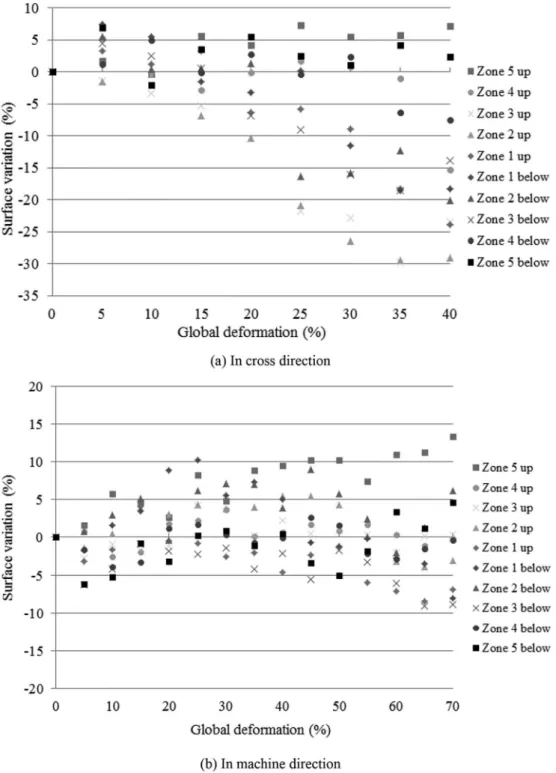
The surface evolution of the ten defined zones as a function of the global deformation of F300 specimen in cross and machine directions is presented inFig. 5. As expected by the observation of
Fig. 1, the surface area variation is not homogenous on the deformed specimen. In the MD, the surface area decreases in zones 1 to 4. It remains globally to a constant value in zone 5 close to the clamps. The maximum reduction of surface area is 35%. In the CD, the variation of surface area is very dependent on the zones. Some Fig. 2. Non-woven fabric specimens, markers and zones.
Table 3
The initial surface area of each zone. Zone Initial surface area
of round zone (mm2)
Initial surface area of square zone (mm2)
1 706.5 900
2 2119.5 2700
3 3532.5 4500
zones have a large decrease (maximum 25% in zone 2 up), some zones have a moderate increase (maximum 12% zone 3 below) and the surface area in some zones remain almost identical. Combining the surface variations in CD and MD, it can be observed that the sample is deformed more easily in MD than in CD. This observation is confirmed by the results of the global behaviour presented in
Fig. 4. Consequently, for tensile tests performed in the CD, the width decreases more rapidly than the expansion on length, and the surface area decreases in almost each zone. Regarding the zones 5, it has little variation of surface (little variation in length and width). The largest surface variations can be noted in the zones close to the central line of the specimens (zones 1 and 2).
The local surface variation as a function of the global deforma-tion curves of tensile test for F450 nonwoven fabric are shown in
Fig. 6. Similar conclusions than for F300 can be suggested. The surface variation is not homogenous. In CD, the surfaces of zones close to the clamps increase weakly (5%) or remain almost stable. Compared to the same zone of F300, it can be observed that the surface area decreases or increases with lower magnitudes. This is due to the fact that cohesion within the F450 fabric is more pro-nounced and is the result of more entanglement and frictions be-tween fibres and bundles constituting the nonwoven fabric. In MD, the surface area of more zones tends to increase; the expansion on length is more rapid than the shortening in width during the tensile test. Compared to F300, F450 is more homogeneous and the vari-ation of the surfaces in MD is less important.
3.2. Bending behaviour
Bending is one of the most important deformation mode for composite reinforcement. The bending stiffness can be determined by KES or cantilever tests[47e49]. This stiffness is low. This may be due to the possible motions between the fibres and. However, the bending stiffness has an important role in the fabric deformability and is one of the parameter that controls the appearance of forming defects such as wrinkling and buckling. Table 5 presents the bending stiffness of nonwoven fabrics F300 and F450 obtained by cantilever test. It can be noted that the bending stiffness in CD is higher than in MD for both F300 and F450 fabrics. Compared to the bending stiffness in MD, it shows an increase of 30% and 50% in CD for F300 and F450 respectively. This suggests that the bending stiffness rise is also related to the increase in areal weight. However, the increase ratio between the F450 and F300 is not identical in CD and MD on the contrary to what was observed for the tensile tests. This may be due to the fact that bending is a combination of both tensile and compressive solicitations.
3.3. Forming of nonwoven fabrics
3.3.1. Observation during forming: local and global deformation steps
As an open matrix is used, it is possible to observe the local and general behaviour of the nonwoven fabrics during forming. To Fig. 3. The hemispherical and square box preforming device.
achieve both hemispherical and square box shapes, several in-vestigations of a preliminary nature were performed. It was observed first that the bending stiffness of both reinforcements is too high in both directions to allow their forming without the use of a blank-holder device. When the blank-holder is used, it was observed that the shape can be obtained even though a careful choice of pressure is necessary to avoid the presence of defects. This will be discussed in the following section.
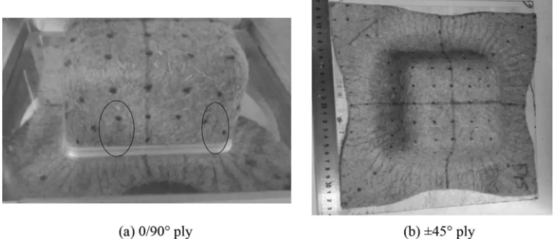
Fig. 7shows the hemispherical and square box shapes at the end of the forming process for both reinforcements and for both initial orientation positioning on the device. During forming, it was observed that both local and global deformations of the rein-forcement (or membrane) takes place. Local deformation of the nonwoven fabric takes place first. This mechanism is characterised by local movement or migration of fibres and groups of fibres (Bundles) within the fibrous structure. The local areas of the re-inforcements are increased and the density of fibre decreases. This phenomenon is particularly visible for the hemispherical forming (Fig. 7a and b) where the size of markers points increases in the useful zone. While local deformations are taking place, no displacement within the blank-holder is observed. In a second phase of the forming process, when the punch reached a certain depth, the global deformation of the membrane starts. This global deformation of the membrane characterised by its sliding under the blank-holder can be evaluated by the draw-in parameter. This Fig. 4. Tensile behaviour on flax-fibre reinforced nonwoven fabric.
Table 4
Tensile stiffness in both directions of the F300 and F450 nonwoven fabrics. Nonwoven fabric Machine direction Cross direction Ratio CD/MD F300 62 ± 3 (N) 79 ± 2 (N) 1.3 ± 0.1 F450 90 ± 5 (N) 115 ± 2 (N) 1.3 ± 0.1 Ratio F450/F300 1.5 ± 0.1 1.5 ± 0.1
phenomenon is detailed in section3.3.3. It is also very interesting to observe that after both hemispherical and square box forming, the 0/90"plies show deformation symmetries in the horizontal and vertical axes (Fig. 7a and c) whereas the deformed ±45"plies are symmetric according to the bias directions. This is once again characteristic of the global behaviour of the fabric during forming that does not take into account the global tension behaviour determined in section3.1. It is therefore essential to understand the forming behaviour of both nonwoven fabrics by investigating global and local properties.
3.3.2. Forming defects
3.3.2.1. Wrinkling. As one of the most common defects, wrinkling
can be observed frequently in woven-textile reinforcement forming
[19,28,50,51]. Boisse et al.[28]have pointed out that wrinkling is a global phenomenon that depends on all strains and stiffnesses. It also depends on the forming boundary conditions. The wrinkles are due to an out of plane deformation mechanism that takes place because too much matter tries to come in a certain zones of the shape. This is the case when two zones of the shape try to come close together. This mechanism cannot really be accommodated by Fig. 5. Local surface variation vs. global deformation in tensile test for F300 nonwoven fabric, (a) in cross direction and (b) in machine direction.
planar deformation within the membrane like it is the case for woven fabrics where in-plane shear takes place. As a consequence, another deformation mechanism appears and this one is charac-terised by out of plane deformation. During the square box forming,
previous studies[19,51]about woven textile showed the high shear deformations on the lateral edges. With nonwoven fabric, as illus-trated in Fig. 8, the notion of in-plane shear does not exist and wrinkles appear.
Fig. 6. Local surface variation vs. global deformation in tensile test for F450 nonwoven fabric, (a) in cross direction and (b) in machine direction.
Table 5
The bending stiffness of tested nonwoven fabrics.
Nonwoven fabric Machine direction Cross direction Ratio CD/MD F300 0.18 ± 0.03 (N mm) 0.24 ± 0.02 (N mm) 1.3 ± 0.1 F450 0.52 ± 0.05 (N mm) 0.80 ± 0.02 (N mm) 1.5 ± 0.1
During the forming the material is subjected to a tensile load coming from the blank-holder pressure and the punch displace-ment. The wrinkling phenomenon can be observed (Fig. 8) for the square box forming of F450 under 0.01 MPa blank-holder pressure. When a small blank-holder pressure is applied during the forming, the tensile load is too weak to prevent wrinkles. However, the wrinkles disappear when a sufficient load is applied. For example, no wrinkles were observed when a blank-holder pressure of 0.2 MPa was applied. When a sufficiently large blank-holder pres-sure is applied, the tension of the membrane increases, and local deformations also increase. In these conditions, less matter tends to come close together and the wrinkling defect does not appear.
3.3.2.2. Slippage/damage of network. Another defect observed in
zones where the fabric shows low fibre area density may be observed. It is characterised by a lack of fibres, or by fibre vacancies. These types of defects are illustrated in Fig. 9 for the F300 nonwoven in both hemispherical and square box forming under a high blank-holder pressure (0.2 MPa).Fig. 9a shows a lack of fibre densities.Fig. 9b and c shows severe damages and a loss of the fabric integrity. This phenomenon is due to the fact that fibres and bundles, submitted to high in-plane tension strains, slide within the fibrous structure towards the outside part of the shape. Lacks of fibre densities at the origin of fibre vacancies can then be observed. As the standard deviation of the areal density of our nonwoven in
initial state is 10% (shown inTable 2), it can be considered that the beginning of the slippage defect begins at 10% evolution of local areal density or 10% evolution of local areal surface. The position of damaged zone depends on the structure of the nonwoven fabric and the forming conditions.
3.3.3. Global scale analysis
3.3.3.1. Material draw-in. During the forming process, one can
expect that the material draw-in is associated to a global defor-mation of reinforcement during the forming process even though local non homogeneous deformations take place. The maximum material draw-in in CD and MD for 0/90" ply and CDþ45" and MDþ45"for ±45"plies are shown inFig. 10. It was measured on pictures taken from a central point of view, perpendicular to the surface of the preform. A sufficient distance was chosen to reduce the errors due to the shooting.Fig. 10a presents only the results of the hemispherical preforming with a 0.2 MPa blank-holder pres-sure because a very weak draw-in was observed in the test using the blank-holder pressure of 0.01 MPa for both materials.Fig. 10b shows draw-in results measured on square box shape under blank-holder pressure of 0.01 MPa for both F300 and F450 nonwoven fabrics and under blank-holder pressure of 0.2 MPa for only F450 fabrics because F300 fabrics were completely damaged (with large vacancies) under the higher pressure (0.2 MPa).
FromFig. 10a it can be noted that a higher draw-in is observed in Fig. 7. Forming results of nonwoven fabric. Hemispherical preforming with blank-holder pressure 0.01 MPa for (a) and (b); Square box preforming with blank-holder pressure 0.2 MPa for (c) and (d).
CD than in MD for 0/90"ply in all of the hemispherical preforming tests. This phenomenon reflects the anisotropy observed during the tensile tests. This is probably due to the fact that the global stiffness in the CD is larger. As a consequence, local deformations take place for higher levels of loads and the draw-in is less affected by local phenomena than for the MD. One can also note that lower draw-ins are observed on the 0/90"F450 reinforcement. This is particularly the case for the MD where the draw-in is decreased by 63% whereas it is only decrease by 13% in the CD. The decrease in draw-in for the
F450 may be due to the fact that the shape is accommodated with more ease as a result of higher local movements within the nonwoven structure as more mater is present in this reinforcement. As a consequence, lower global movement of the membrane is required. In this case, one can conclude that even if draw-in is characteristic of a global material scale movement, this one also depends, in a large extent, on local deformations.
In ±45 "ply preforming, the draw-ins through CDþ45 "and MDþ45"
do not show any significant difference. It is due to the Fig. 8. Wrinkling phenomenon in F450 nonwoven fabric during forming.
loading conditions and this behaviour is classical and in accordance to the ones observed for non-balanced woven fabrics [52]. The comparison between the two materials shows that the draw-in is strongly depends on the areal weight of nonwoven fabric. This therefore reflects the fact that the nonwoven fabrics exhibit a global identified behaviour during forming as the material is more rigid.
Fig. 10b shows that no significant difference can be observed between the draw-in measured in the 0/90"
forming between the F300 and the F450 fabrics for the 0.01 MPa blank-holder pressure. As the blank-holder pressure is low the fabric has the ability to slide easily between them and the matrix without any local deformation between the shape and the blank-holder. One can also observe that the reinforcements are not completely tightly placed on the square box shape. This was actually confirmed by the presence of wrin-kling defects when a low blank-holder pressure was used. Similar results were observed for the ±45"directions. With a higher blank-holder pressure, the draw-in was increased for both 0/90 "and ±45"for the F450 reinforcement. This is due to the fact that the
reinforcement is in this case more tightly placed on the shape and in these conditions, more material needs to slide between the blank-holders to accommodate the shape. Draw-in increase (for the higher blank holder pressure) of 40% can be observed in both MD and CD for 0/90"positioning and 70 and 60% increase for MDþ45" and CDþ45"for the ±45"positioning. The draw-in increase in the ±45"positioning is larger than for the 0/90"case because lower local deformations were recorded for this initial positioning (Fig. 13
in local scale analysis).
3.3.3.2. Punch force. The punch force required to apply in order to
maintain the fabric on the punch at the end of the forming process was measured and shown inTable 6. It can be noted in a first extent that a larger punch force is required for the same fabric when a higher blank-holder pressure was used. This was expected because the role of the blank-holder is to control and limit the movement of the fabric by applying a pressure on it. When submitted to a higher holder pressure, the sliding of the fabric between the
blank-(a) in hemispherical preforming
(b) in square box preforming
0
2
4
6
8
10
12
14
16
18
20
m
u
mi
xa
M
m
wa
r
d
la
ir
et
a
-ni
)
m
m(
MD CD MD CD MD+45° CD+45° MD+45° CD+45°F300 0/90°ply F450 0/90°ply
F300 ±45°ply
F450 ±45°ply
blank-holder pressure 0.2 MPa
m
u
mi
xa
M
m
wa
r
d
la
ir
et
a
-ni
)
m
m(
MD MD MD+45° MD+45° MD MD+45°F300
0/90°ply
F450
0/90°ply
F300
±45°ply
F450
±45°ply
F450
0/90°ply
F450
±45°ply
blank-holder pressure
0.01 MPa
blank-holder pressure
0.2 MPa
CD CD CD+45° CD+45° CD CD+45°0
5
10
15
20
25
30
35
40
45
50
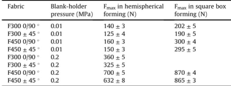
holder and the matrix becomes more and more difficult and re-quires a higher punch force. Under the same blank-holder pressure, the punch force is slightly higher for the preforming of 0/90"ply than for the ±45"ply. For the same orientation, a more important force is required to achieve the preforming of F450 fabric than the preforming of F300 fabric. The difference is probably due to the higher cohesion of the fibres and bundles within the fibrous structure. This is due in our case to the higher areal weight of the F450 fabric. As the cohesion due to more entanglement implies more friction when the local strains takes place, a higher load is required to locally deform the structure before.
Moreover, under the same forming conditions, the square box preforming requires a higher load than for the hemispherical pre-forming. This is mainly attributed to a larger displacement of the punch and to the complex shape geometry of this punch that imply higher local deformations (shown inTable 7). The maximum punch force cannot be noted in the square box preforming of F300 fabric under 0.2 MPa pressure, as the network of nonwoven fabric is completely damaged.
3.3.4. Local scale analysis of fibre density
As presented previously in tensile tests, the nonwoven fabrics do not deform homogeneously. Strong variation of area density in each local zone during the forming may be observed. In order to quantify the evolution of local area density, the measurement of local surface area was performed. It was considered that no fibre leaves its original area. The initial surface area of each zone is given inTable 3. After the forming the surface area of each zone was measured.
3.3.4.1. In hemispherical forming.Fig. 11 shows that the initially circularly placed markers points keep their circular geometry in all of the five defined zones. Moreover, the markers point themselves increase in size but keep their circular geometry. Consequently, zone 1 is a spherical cap and zones 2e5 are one part of spherical cap. The curved surface area of the spherical cap can be calculated by using equation(1):
S ¼ 2
p
Rh (1)where R is the radius of sphere and h is the height of the cap. The height of the cap was directly measured on the shape, but it is directly dependent on the imposed punch displacement. In ge-ometry, the radius of the base of the cap (ai) observed in lateral view (Fig. 11b) is equal to the radius of circle (ri) observed in bottom view (Fig. 11a). Thanks to the markers, rican be measured by optical method. Consequently, the points 1e4 can be obtained on the 3D deformed shape noted inFig. 11b. When the positions of the points 1e4 are determined, the height of the cap hi can be measured geometrically.
Fig. 12presents the percentage increase of surface area for each local zone (seeFig. 2) of F300 fabric after the hemispherical forming for 0/90"and ±45"orientations under two different blank-holder pressure conditions. For the two orientations, the defined areas follow the same evolution. For F300 under a weak blank-holder pressure (0.01 MPa), the surfaces evolution shows, from the top of the hemisphere, an increasing of the percentage then a decreasing when getting closer to the base of the hemisphere. The zones closer to the blank-holder (base of the useful zone) have smaller surface increases and the surface of the zone 5 remains unchanged. For 0/90"oriented blanks submitted to a high blank-holder pressure (0.2 MPa), the percentage increase of the surfaces is more important, and the evolution of surfaces area decreases almost linearly from the top to the base of the hemisphere. The top zone (zone 1) deformed at first, has a biggest augmentation of surface area (z47%). For this fabric, the measurements confirm a strong inhomogeneity of the local density in each zone which evolution depends on the pressure applied and on the initial orientation. For the ±45"orientation similar trends are observed, with however larger surface increases (a maximum of 60% in comparison to 47%) in the case of the 0.2 MPa blank-holder pres-sure. The ±45"is therefore more sensitive to the surface increase for a similar blank-holder pressure and probably to the appearance of the vacancy defect.
Fig. 13shows the evolution of surfaces during the hemispherical forming for the F450 fabrics. Compared to F300 0/90"ply, a similar surface increase evolution can be observed for 0.01 MPa blank-holder pressure. The surface increases are however larger than for the F300 and can reach values of about 45% that are higher by 10% than for the F300 value. For a strong blank-holder pressure the F450 fabrics exhibit a more homogeneous behaviour, illustrated by nearly identical surface increases in all zones. All the surfaces, in the useful zone of the hemisphere are deformed quasi similarly during forming. The levels of surface increase are globally higher (up to z70%) than for the F300 reinforcement, and the zones close to the base of hemisphere (zones 4 and 5) have a significant increase of their surfaces on the contrary to what was observed on the F300 fabric. One can believe that the loads leading to the homogeneous strains are more equally distributed within the fibrous structure. This may be attributed to the larger amount of fibres which allows better distribution of the loads in all the membrane without local concentrations. For the ±45 " orientation, similar trends were observed than for the 0/90"orientation.
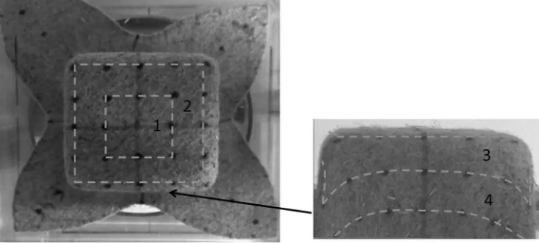
3.3.4.2. In square box forming. The deformed zones after square
box forming are shown inFig. 14. From initial positions only zones 1 and 2 remains on the top face of the square box and their surfaces can be measured. For the square box forming, the initial square zones (1 and 2) do not completely keep their initial geometry and rectangles zones can be observed inFig. 14even though this phe-nomenon is not very much pronounced. The tensile behaviour anisotropy is therefore present at this level but with a relative low Table 6
The punch force after nonwoven fabrics forming Fmax. Fabric Blank-holder
pressure (MPa)
Fmaxin hemispherical forming (N)
Fmaxin square box forming (N) F300 0/90" 0.01 140 ± 3 202 ± 5 F300 ± 45" 0.01 125 ± 4 190 ± 5 F450 0/90" 0.01 160 ± 3 300 ± 4 F450 ± 45" 0.01 150 ± 3 295 ± 5 F300 0/90" 0.2 360 ± 5 F300 ± 45" 0.2 325 ± 5 F450 0/90" 0.2 700 ± 5 870 ± 4 F450 ± 45" 0.2 632 ± 8 865 ± 3 Table 7
The percentage increase of surface area of zones 1 and 2. Fabric Blank-holder
pressure (MPa)
Percentage increase of area surface Zone 1 Zone 2 F300, 0/90" ply 0.01 82 ± 3% 83 ± 5% 0.2 Damage of network F300, ±45" ply 0.01 81 ± 6% 80 ± 7% 0.2 Damage of network F450, 0/90" ply 0.01 79 ± 3% 75 ± 5% 0.2 111 ± 3% 102 ± 4% F450, ±45" ply 0.01 66 ± 4% 72 ± 3% 0.2 98 ± 5% 89 ± 6%
magnitude in comparison to the one measured during the tensile tests. Zone 3 is located, after preforming, between the top and the side faces. It is very difficult to measure precisely the surface area of deformed zone 3. As there is one part of the deformed zone 4 outside the useful zone, it is not interesting to obtain surface area of this zone. This work therefore concentrates on zones 1 and 2 for the previously exposed reasons. The percentage increases of surface area of these zones after forming are reported inTable 7, for both orientations and pressure conditions. The surface increase mea-surements were not performed for the F300 fabric forming sub-mitted to 0.2 MPa blank-holder pressure because large vacancies of fibre were taking place and completely damaged the fabric. At equivalent conditions of forming (orientation, pressure applied), compared to F450 fabric forming, the percentage increase of sur-face area in the same zone is more important for the F300 fabric forming. Surface increases of more than 80% are observed on the F300 fabric for low blank holder pressure. Almost similar surface increases were evaluated on the F450 fabric for the same blank-holder pressure for the 0/90" ply and lower increases for the ±45"ply (66 and 72% for zones 1 and 2 respectively). It is also important to note that large surface increases were measured in zones 1 and 2 of the formed square boxes. Larger surface increases superior to 100% (up to 111% in zone 1) were also measured while the reinforcement was submitted to the 0.2 MPa pressure for the 0/
90" initial positioning. Surface increases of 98 and 89% were measured for the ±45"direction. The percentage increases with the pressure, but it is higher than the ones obtained during the hemi-spherical forming, due to the higher global load applied (Table 6). At this level of load, the evolution of surfaces seems to be more homogeneous between zones.
4. Discussion: specificities associated to the forming of nonwoven fabrics
The results presented in section 3show that it is possible to perform double curvature shapes from commercially available nonwoven fabrics such as a hemisphere. A more complex shape with triple curvature points was also formed with success. How-ever, forming defects may appear and it is important to predict the feasible process conditions. In a first extent, it is important to use a blank-holder system to apply a sufficient tension level to the fabric. This is necessary to prevent the appearance of the wrinkling defect that is due to in-plane compression of the fabric membrane. By applying a sufficient tension on it, the compression effect can be annealed. However, this level of tension should not be too high as this may be the cause of vacancy appearance. The vacancies are characterised by local lacks of fibre density and are due to local migration of fibres towards tension loads points. This work shows Fig. 11. Local surface area measurement for deformed hemispherical ply.
however that for the square box forming, the nonwoven fabric with the higher areal weight is more suitable to realize this complex shape as very large local surface increases take place in several local zones of the shape. The surface increase in particular zones of the shape may reach values that can be higher than 100% without visually observing the vacancy defect. This clearly indicates that the deformation potential of the nonwoven fabrics is therefore important especially if the initial areal weight is sufficient to allow local fibre migrations in high in-plane tension zones. The defor-mation potential of the fabric is probably dependant on the cohe-sion of the fibres and bundles within the fibrous structure. This cohesion level should be sufficiently high to avoid any premature degradation with fast appearance of vacancies, but not too impor-tant to allow the local migrations of fibres.
However, as several local surfaces increase, the fibre density also locally decreases in some specific zones of the shape. The in-plane and transverse permeabilities are therefore not homogeneous and this should be taken into account for the impregnation process by the Liquid Composite Moulding process for example. This point should also be considered by the composite part designer to predict the mechanical properties of their part.
This work also demonstrated that local and global deformations of the fibrous membrane did not necessarily take place simulta-neously. At the beginning of forming, local tensile deformation at the origin of surface increases takes place in a first extent. From a punch depth that depends on the shape of the fabric, the process parameters, the material properties, the global deformation mechanism of the membrane is activated and is characterised by draw-in that only appears at that time. The draw-in magnitude is direction dependant when the test specimens are place with a 0/ 90"orientation. This point is in good agreement with the global anisotropic tensile behaviour of the fabric (due to the fibre align-ment during the manufacturing process) determined by out of the process tests.
The local deformations have been measured during nonwoven fabrics forming. Symmetrical local deformations at 0 and 90" ori-entations of the fabrics were observed during the hemispherical forming, and low extent anisotropy was observed for the square box forming. This point is particularly interesting and represents a specificity of the nonwoven fabric behaviour during forming. Even if the anisotropic behaviour of the fabrics was clearly established by the tensile test and well understood by the alignment of fibres
(a) F300, 0/90° ply
(b) F300,
±
45° ply
1
2
3
4
5
es
ae
rc
ni
e
ga
t
ne
cr
e
p
e
h
T
0%
5%
10%
15%
20%
25%
30%
35%
40%
45%
50%
Zone N
°
0.01 MPa 0.2 MPa1
2
3
4
5
es
ae
rc
ni
e
ga
t
ne
cr
e
p
e
h
T
Zone N
°
0%
10%
20%
30%
40%
50%
60%
70%
0.01 MPa 0.2 MPaFig. 12. The percentage increase of surface area of each local zone during F300 nonwoven fabric forming.
(a) F450, 0/90° ply
(b) F450,
±
45° ply
1
2
3
4
5
es
ae
rc
ni
e
ga
t
ne
cr
e
p
e
h
T
Zone N
°
0%
10%
20%
30%
40%
50%
60%
70%
80%
0.01 MPa 0.2 MPa1
2
3
4
5
es
ae
rc
ni
e
ga
t
ne
cr
e
p
e
h
T
Zone N
°
0%
10%
20%
30%
40%
50%
60%
70%
80%
0.01 MPa 0.2 MPaFig. 13. The percentage increase of surface area of each local zone during F450 nonwoven fabric forming.
during the manufacturing process, the results of the tensile test should be observed with a certain care. Particularly, one could expect that the maximum deformation levels determined during these tests are the maximum limits that should not be overcome locally during surface increases. This probably means that both parameters are probably not directly related because surface in-creases larger by a great extent than the maximum limit estab-lished during the tensile test were measured. Local tensile strains should therefore be measured during forming to establish a better link between the forming observations and the tensile tests. The lack of correspondence between the tensile deformation values and the surface increases may also be due to size effect of the tensile test specimens that are not convenient for this type of character-ization and to different fibre distribution that take place during the tensile test and the forming process.
5. Conclusions
The production of nonwoven fabrics from natural fibres required less energy than classical woven fabrics. These materials are already produced at an industrial level for simple curvature semi-structural part in the automotive industry. To develop their use for technical applications this work investigates the possibility to form double curvature parts such as a hemisphere as well as a more complex shape such as a square box which possess four triple curvature points. By choosing the right process parameters and reinforcements with sufficiently large enough areal weights, it is demonstrated that it is possible to form the expected shapes without any apparent defect such as vacancies or wrinkles. The high deformation potential of the nonwoven fabrics is established. The specific behaviour of the nonwoven fabrics is studied by ana-lysing the local and global deformation mechanisms of the rein-forcement during forming. During the process, local deformations characterised by the increase of surface of defined zones and a global deformation of the fabric that is characterised by the draw-in under the blank-holder. The variation of the local surface area as a function of the local fibre density will be an important parameter to characterize the deformability of nonwoven fabric and its conse-quence on the permeability during resin injection step. The specific behaviour of the nonwoven fabric should be taken into account for future modelling of the forming and impregnation processes. Acknowledgments
This research was financially supported by BPI-France, under the project ‘SINFONI’.
References
[1]Das D. In: Das D, Pourdeyhimi B, editors. Introduction to composite non-wovens in “composite nonwoven materials structure, properties and appli-cations”. Woodhead Publishing Series in Textiles; 2014. Number 155. [2]Thilagavathi G, Pradeep E, Kannaian T, Sasikala L. Development of natural fiber
nonwovens for application as car interiors for noise control. J Ind Text 2010;39(3):267e77.
[3]Vasile S, Van Langenhove L. Automotive industry e a high potential market for nonwovens sound insulation. J Text Appar, Technol Manag 2004;3(4):1e5. [4]Russell S. Handbook of nonwovens. Woodhead Publishing; 2007.
[5]Soukupova V, Boguslavsky L, Anandjiwala RD. Studies on the properties of biodegradable wipes made by the hydroentanglement bonding technique. Text Res J 2007;77:301e11.
[6]El Hajj N, Mboumba-Mamboundou B, Dheilly RM, Aboura Z, Benzeggagh M, Queneudec M. Development of thermal insulating and sound absorbing agro-sourced materials from auto linked flax tows. Ind Crop Prod 2011;34:921e8. [7]Tascan M, Vaughn EA, Stevens KA, Brown PJ. Effects of total surface area and fabric density on the acoustical behavior of traditional thermal-bonded highloft nonwoven fabrics. J Text Inst 2011;102:746e51.
[8]Vigneswaran C, Chandrasekaran K, Senthilkumar P. Effect of thermal con-ductivity behavior of jute/cotton blended knitted fabrics. J Ind Text 2009;38: 289e307.
[9]Misnon MI, Islam MM, Epaarachchi JA, Lau KT. Potentiality of utilising natural textile materials for engineering composites applications. Mater Des 2014;59: 359e68.
[10] Smith PA. Technical fabric structures e3. Nonwoven fabrics. In: Horrocks AR, Anand SC, editors. Handbook of technical textiles. The Textile Institute, North and South America: Woodhead Publishing Limited; 2000.
[11] Dissanayake N, Summerscales J, Grove S, Singh M. Life cycle impact assess-ment of flax fibre for the reinforceassess-ment of composites. J Biobased Mater Bioenergy 2009;3:245e8.
[12] Miao M, Shan M. Highly aligned flax/polypropylene nonwoven preforms for thermoplastic composites. Compos Sci Technol 2011;71:1713e8.
[13] Shah DU. Natural fibre composites: comprehensive Ashby-type materials se-lection charts. Mater Des 2014;62:21e31.
[14] Farukh F, Demirci E, Sabuncuoglu B, Acar M, Pourdeyhimi B, Silberschmidt VV. Mechanical behaviour of nonwovens: analysis of effect of manufacturing parameters with parametric computational model. Comput Mater Sci 2014;94:8e16.
[15] Farukh F, Demirci E, Sabuncuoglu B, Acar M, Pourdeyhimi B, Silberschmidt VV. Mechanical analysis of bi-component-fibre nonwovens: finite-element strat-egy. Compos Part B 2015;68:327e35.
[16] Long AC. Composites forming technologies. New York, NY: CRC Press; 2007. [17] Christos K. Design and analysis of composite structures: with application to
aerospace structures. New York, NY: Wiley; 2010.
[18] Campbell F. Manufacturing technology for aerospace structural materials. Lavoisiers: Elsevier; 2006.
[19] Allaoui S, Hivet G, Soulat D, Wendling A, Ouagne P, Chatel S. Experimental preforming of highly double curved shapes with a case corner using an interlock reinforcement. Int J Material Form 2014;7(2):155e65.
[20] Zhu B, Yu TX, Zhang H, Tao XM. Experimental investigation of formability of commingled woven composite preform in stamping operation. Compos Part B 2011;42:289e95.
[21] Khan MA, Mabrouke T, Vidal-Sall!e E, Boisse P. Numerical and experimental analyses of woven composite renforcement forming using a hypoelastic behaviour. Application to the double dome benchmark. J Mater Process Technol 2010;210:378e88.
[22] Allaoui S, Cellard C, Hivet G. Effect of inter-ply sliding on the quality of
multilayer interlock dry fabric preforms. Compos Part A 2015;68:336e45. [23] Haanappel SP, ten Thije RHW, Sachs U, Rietman B, Akkerman R. Formability
analyses of uni-directional and textile reinforced thermoplastics. Compos Part A 2014;56:80e92.
[24] Harrison P, Gomes R, Curado-Correia N. Press forming a 0/90 cross-ply advanced thermoplastic composite using the double-dome benchmark ge-ometry. Compos Part A 2013;54:56e69.
[25] Yin H, Peng X, Du T, Guo Z. Draping of plain woven carbon fabrics over a double curvature mold. Compos Sci Technol 2014;92:64e9.
[26] Vanclooster K, Lomov SV, Verpoest I. Experimental validation of forming simulations of fabric reinforced polymers using an unsymmetrical mould configuration. Compos Part A 2009;40(4):530e9.
[27] Thomas G, Oliver D, Matthias H, Chokri C. Experimental and computational composite textile reinforcement forming: a review. Compos Part A 2013;46: 1e10.
[28] Boisse P, Hamila N, Vidal-Sall!e E, Dumont F. Simulation of wrinkling during textile composite reinforcement forming. Influence of tensile in-plane shear and bending stiffnesses. Compos Sci Technol 2011;71(5):683e92.
[29] Jauffr!es D, Sherwood JA. Discrete mesoscopic modeling for the simulation of wovenfabric reinforcement forming. Int J Material Form 2010;3:1205e16. [30] Peng X, Guo Z, Diu T, Yu WR. A simple anisotropic hyperelastic constitutive
model for textile fabrics with application to forming simulation. Compos Part B 2013;52:275e81.
[31] Boisse P, Aim"ene Y, Dogui A, Dridi S, Gatouillat S, Hamila N, et al. Hypoelastic, hyperelastic, discrete and semi-discrete approaches for textile composite reinforcement forming. Int J Material Form 2010;3:1229e40.
[32] Hamila N, Boisse P. Simulations of textile composite reinforcement draping using a new semi-discrete three node finite element. Compos Part B 2008;39: 999e1010.
[33] Ouagne P, Soulat D, Moothoo J, Capelle E, Gueret S. Complex shape forming of a flax woven fabric; analysis of the tow buckling and misalignement defect. Compos Part A 2013;51:1e10.
[34] Capelle E, Ouagne P, Soulat D, Duriatti D. Complex shape forming of flax woven fabrics: design of specific blank-holder shapes to prevent defects. Compos Part B 2014;62:29e36.
[35] Bel S, Hamila N, Boisse P, François D. Finite element model for NCF composite reinforcement preforming: importance of inter-ply sliding. Compos Part A 2012;43:2269e77.
[36] Duhovic M, Mitschang P, Bhattacharyya D. Modelling approach for the pre-diction of stitch influence during woven fabric draping. Compos A 2011;42(8): 968e78.
[37] Lee J, Hong S, Yu W, Kang T. The effect of blank holder force on the stamp
forming behavior of non-crimp fabric with a chain stitch. Compos Sci Technol 2007;67:357e66.
[38] Dufour C, Wang P, Boussu F, Soulat D. Experimental investigation about stamping behavior of 3D warp interlock composite preforms. Appl Compos Mater 2014;21:725e38.
[39] Li XK, Bai SL. Sheet forming of the multi-layered biaxial weft knitted fabric reinforcement. Part I: on hemispherical surfaces. Compos Part A 2009;40(6e7):766e77.
[40] Jacquot PB, Wang P, Soulat D, Legrand X. Analysis of the preforming behaviour of the braided and woven flax/polyamide fabrics. J Ind Text 2016;46(3): 698e718.
[41] Zhang F, Comas-Cardona S, Binetruy C. Statistical modeling of in-plane permeability of non-woven random fibrous reinforcement. Compos Sci Technol 2012;72:1368e79.
[42] Xue D, Miao M. Influences of moisture absorption and chemical treatments on the resin flow characteristics of natural fibre nonwoven mats. J Text Inst 2012;103:1024e30.
[43] Xue D, Miao M, Hu H. Permeability anisotropy of flax nonwoven mats in vacuum-assisted resin transfer molding. J Text Inst 2011;102:612e20. [44] Prodromou AG, Chen J. On the relationship between shear angle and
wrin-kling of textile composite preforms. Compos Part A 1997;28A:491e503. [45] Syerko E, Comas-Cardona S, Binetruy C. Models for shear properties/behavior
of dry fibrous materials at various scales: a review. Int J Mater Form 2015;8: 1e23.
[46] Chen X, Chen L, Zhang C, Song L, Zhang D. Three-dimensional needle-punching for composites e a review. Compos Part A 2016;85:12e30. [47] Kawabata S. The standardization and analysis of hand evaluation. Osaka: The
Textile Machinery Society of Japan; 1986.
[48] Lahey TJ, Heppler GR. Mechanical modeling of fabrics in bending. ASME J Appl Mech 2004;71:32e40.
[49] De Bilbao E, Soulat D, Hivet G, Gasser A. Experimental study of bending behaviour of reinforcements. Exp Mech 2010;50:333e51.
[50] Wang P, Hamila N, Boisse P. Thermoforming simulation of multilayer com-posites with continuous fibres and thermoplastic matrix. Compos Part B 2013;52:127e36.
[51] Wang P, Legrand X, Boisse P, Hamila N, Soulat D. Experimental and numerical analyses of manufacturing process of a composite square box part: compar-ison between textile reinforcement forming and surface 3D weaving. Compos Part B 2015;78:26e34.
[52] Tephany C, Soulat D, Gillibert J, Ouagne P. Influence of the non-linearity of fabric tensile behavior for preforming modeling of a woven flax fabric. Text Res J 2016;86(6):604e17.