Development of Self-Folding Origami Sensors Through the Use of Resistance, Capacitance, and Inductance
by
Laura Meeker
Submitted to the
Department of Mechanical Engineering
in Partial Fulfillment of the Requirements for the Degree of Bachelor of Science in Mechanical Engineering
at the
Massachusetts Institute of Technology
February 2014
C 2013 Massachusetts Institute of Technology. All rights reserved.
Signature redacted
Signature of Author:Certified by:
Department of Mechanical Engineering January 30, 2014
Signature redacted
Daniela Rus Professor of Electrical Engineering and Computer Science Thesis Supervisor
Signature redacted
Anette Hosoi Professor of Mechanical Engineering Undergraduate Officer Accepted by: OF MCHNCLOGY
jjL
3
0
201
LIBRARIES
'%--0-1Development of Self-Folding Origami Sensors Through the Use of Resistance, Capacitance, and Inductance
by
Laura Meeker
Submitted to the Department of Mechanical Engineering on January 30, 2014 in Partial Fulfillment of the
Requirements for the Degree of
Bachelor of Science in Mechanical Engineering
ABSTRACT
Though robotics is still perceived as a very "high-tech" field and largely associated with academia and industry, accessibility and demand for the accessibility of robots is on the rise. A variety of efforts to meet this demand include the design and manufacture of "printable" robots through the use of 3D printers or foldable robotic components. This thesis sought to address the need for printable sensors through the use of self-folding, conductive origami. Using Miyashita's technique for self-folding origami through global heat application, a several sensors were
designed and fabricated. A variable resistor design can detect compression via shorting between tiles (thereby decreasing resistance). Smoother detection of compression was achieved through measurement of capacitance in a design which connected alternate rows of tiles. Lastly,
inductance and magnetic field of a folded coil were measured as part of an exploration into the potential for printable actuation. Using the magnetic field produced by a 24-winding coil under 5A of current, actuation was achieved in the form of small compression (up to I mm) of the coil.
Thesis Supervisor: Daniela Rus
Acknowledgments
The author would like to thank Professor Daniela Rus for her guidance and sponsorship of the project as well as Shuhei Miyashita for his invaluable mentorship throughout.
Table of Contents Abstract 3 Acknowledgements 5 Table of Contents 7 List of Figures 9 List of Tables 11 1. Introduction 13 1.1 Motivation 13 1.2 Current State 13
1.2 Printable Sensors and Actuators 15
2. Resistance 17
2.1 Motivation and Overview 17
2.2 Modeling Resistance 17
2.3 Resistive Sensor 21
3. Capacitance 25
3.1 Motivation and Overview 25
3.2 Modeling Capacitance 25
3.3 Measuring Capacitance 26
3.4 Capacitive Sensor 27
4. Inductance and Magnetic Field 31
4.1 Motivated by Actuation 31
4.2 Model and Measurement of Coil Inductance 31
4.3 Magnetic Field 32
4.4 Harnessing Magnetic Field for Actuated Compression 34
5. Conclusions and Future Work 37
5.1 Conclusions 37
5.2 Future Work 37
5.3 Lessons Learned 38
6. Appendices 41
Appendix A: Iterative solution for sheet resistance 41
List of Figures Figure 2.1: Figure 2.2: Figure 2.3: Figure 2.4: Figure 2.5: Figure 2.6: Figure 2.7: Figure 3.1: Figure 3.2: Figure 3.3: Figure 3.4: Figure 3.5: Figure 4.1: Figure 4.2: Figure 4.3: Figure 4.4: Figure 4.5:
The van der Pauw method of measuring sheet resistance 18 Resistance vs. length-to-width ratio for a variety of rectangular dimensions 19 Effect of bridge dimensions and location on the resistance of a square tile 20 The process for self-folding a spring-like electrical switch 22 Demonstration of the spring-like electrical switch 23
Crease pattern for a stretchable resistor 23
Stretchable resistor before and after self-folding 24 Setup for derivation of the capacitance between two angled tiles 25 Model vs. measurements for the capacitance between angled square tiles 27 Basic crease pattern for horizontal conduction through mountain folds 28 Manufacture of a capacitive sensor, from [8] Miyashita et. al. 29 Measurement of capacitance vs. axial length (compression) 30
A 24-winding hand-folded coil 31
Effect of ferrous core on the magnetic field produced by a folded coil 33 Magnet flip caused by the magnetic field of a coil 33 Setup for the contraction of a hand-folded coil via attraction between two ferrous cores 34 Measured contraction of a coil at various currents using the setup shown in Figure 4.4 35
List of Tables
TABLE 2.1: Calculation of resistances A and B for use in the van der Pauw method of
1. Project Introduction, Motivation and Background
1.1 Motivation
Robotics is often perceived as an extremely "high-tech" field, requiring specialized knowledge and expensive equipment. In the last few decades, robots have become essential in some parts of the industrial realm and have maintained a solid presence in academia as well. Robots are beginning to make their way to the general public (via children's toys, educational use, or the well-known Roomba made by iRobot), in response to an increased demand. Now more than ever, desire for rapid prototyping (such as 3-D printing) and personal, at-home robotics is on the rise. Printable, foldable robots are one way that a demand for improved accessibility might be met.
Despite many advancements in origami-inspired and otherwise foldable robots, there still exists the hurdle of developing "printable" sensors and actuators to augment other printable robotic components. If these actuators and sensors could be developed, a truly printable robot could be designed and manufactured. Due to the electrical nature of most sensors and actuators, printing and folding them presents a unique challenge as compared with producing the only the physical structure of a printable, self-folding robot. This work in this thesis attempts to address a need for printable sensors through development of self-folding conductive origami.
1.2 Current State
Some advancements have already been made in the field of foldable, printable electronics and robotics. A 2009 paper by Benbernou et. al. describes a universal crease pattern which "can fold into any object made up of unit cubes joined face-to-face.E'1" This crease pattern ("tetrakis tiling" or "box pleating" was later used by Hawkes et. al. in their 2010 paper "Programmable
Matter by Folding." This paper explored of the use of shape memory alloys for actuation along predetermined creases. The programmable matter can be folded using localized application of heat (and later unfolded, as well)[21. In 2011, Paik et. al. developed flexible circuits and sensors
to be used along creases in structures like Hawkes' programmable matterp3 .
In addition to the applied-heat, shape memory alloy method of folding actuation, some researchers have explored the use of magnetic actuation. In 1997, Judy and Muller described a method they developed for using magnetic field to lift a small nickel-coated flap. [']. Yi and Liu
later used a similar concept to lift flaps about set of hinges5 . After using magnetic field to lift a
set of flaps, strategically placed slots and tabs locked the flaps together and allowed them to hold their three dimensional structure.
In 2008, Okuzaki et. al. used a simple, manually-folded conductive origami shape to produce an structure which moved by use of expansions and contractions (a result of applied voltage), similar to an inchworm[61. A few other folded worm-like robots have been made since
(though the folded portions were not necessarily self-actuating as in Okuzaki's origami). In the 2011 paper titled "Towards Printable Robotics: Origami-Inspired Planar Fabrication of Three-Dimensional Mechanisms" by Onal et. al., a variety of manually-folded origami structures were produced . In one case, actuators were attached to produce a "peristaltic crawling" worm robot.
Similarly, a self-folding inchworm robot was produced by Felton et. al in 2013, as described in their paper "Robot Self-Assembly by Folding: A Printed Inchworm Robot"8 .
Further research into self-folding robotics was completed by Miyashita et. al. as described in their 2013 paper "Self-pop-up Cylindrical Structure by Global Heating"191. The
sheet used for the cylindrical structure in Miyashita's paper is comprised of "rigid" outer layers combined with a shrinking internal layer. By implementing varying gap sizes along desired fold
lines in the rigid layers, Miyashita succeeded controlling fold direction and angle. All self-folding origami in this thesis were produced using Miyashita's global uniform heating method.
In addition to the use of Miyashita's self-folding method, a basic spring-like origami form was used as inspiration for several of the origami patterns in this thesis. In "Geometrical properties of paper spring," Min and Suzuki describe the physical merits of deployable springs, including their potential use in a shock-absorbing system or as a deployable truss ['1. Though similar shapes were used, the emphasis in this thesis is placed more on the use of spring-like origami for compressible and flexible sensors (that aren't necessarily load-bearing).
1.3 Printing sensors and actuators
The work described in this thesis covers the use of resistive, capacitive, and inductive properties of a variety of self-folded conductive origami to produce sensors and demonstrate potential for printable actuation. Using spring-like shapes for inspiration, a self-folded resistive switch and a capacitive compression sensor were developed. The capacitive compression sensor could conceivably be used on board a printable robot as a force sensor to detect obstacles. Further, a stretchable resistive sensor was self-folded and origami coils were developed to explore the use of magnetic field in printable actuators. In addition to the conductive origami pieces that were designed and tested, models of the resistive, capacitive, and inductive properties were developed and compared with measurements in order to inform future design of conductive origami.
2. Resistance
2.1 Motivation and Overview
Because a truly printable robot requires printable sensors, an effort was made to utilize the inherent electrical resistance of the origami structures to develop sensing capability.
Measuring changes in resistance is one way that conductive origami might be used to sense a variety of changes in environment, including force and displacement. Before developing resistive sensors, the inherent resistive properties of the metallic polyester film were investigated by modeling and measuring sheet resistance. Two types of self-folding resistive sensors were then developed, and usefulness as a sensor was demonstrated by lighting an LED as an origami "spring" was compressed by hand.
2.2 Modeling Resistance
In an attempt better understand the inherent resistive qualities of the material being used for construction of self-folding origami, a model was developed to approximate resistance using tile and bridge dimensions. To develop this model, it was necessary to ascertain the particular
sheet resistance of the conductive polyester material (Mylar) used for production of the self-folding origami. Additionally, bridge effects were taken into account by measuring resistance for varying length to width ratios of the bridge.
2.2.1 Sheet Resistance using the Van der Pauw Method
In his 1958 paper "A Method of Measuring the Resistivity and Hall Coefficient on Lamellae of Arbitrary Shape," L.J. van der Pauw provides a simple method for determining the sheet resistance of a conductive material [. By applying a current across consecutive corners of
a sheet and measuring the voltage across the opposite corners, a resistance value can be calculated as per Figure 2.1 and the corresponding equations below:
V
1 2
2
4 3
A
B
Figure 2.1 - The van der Pauw method of measuring sheet resistance. Current applied across consecutive corners with voltage measured across the opposite corners.
RA = VA IA RB = VB IB [2.11 [2.2]
The measured values of RA and RB for a steadily applied current are given in Table 2.1 below:
Direction Applied Current Measured Voltage (mV) Resistance (0)
RA 140 mA 29.1 .2079
RB 140 mA 28.5 .2036
Table 2.1 - Measured voltage for an applied current of 140 mA, and the corresponding resistance. Each measurement (RA and RB) was taken four times. This table shows the mean of those measurements. Using the resistance values defined in equations 2.1 and 2.2, van der Pauw provides the following equation which is solvable for a sheet resistance value (Rs):
-RA -RB
Solving iteratively in MATLAB using the measured values of RA and RB provided in Table 2.1 gives an Rs value of .932. Please see Appendix A for the MATLAB script used to iteratively solve for Rs.
After calculating theoretical sheet resistance using the van der Pauw method, measurements of a variety of rectangular dimensions were taken. These measurements are compared with the model R = Rs in Figure 2.2 below.
Resistance vs. (length/width)
25-0 measured data points
tit to measured data
20 - model (932x)
model with additonal constant term ( 32x + 1 8
E
0
0 2 4 6 8 10 12 14 16 18 20
lengthvWidth
Figure 2.2 - Resistance vs. length-to-width ratio for a variety of rectangular dimensions of metallized polyester film. Slope here denotes sheet resistance. Green shows the predicted resistance of a given length:width ratio, calculated using the van der Pauw sheet resistance. The slope of the model (sheet resistance) is correct, though the addition of a constant to the model improves the prediction (shown in red). The resistance of each length:width ratio was measured once.
As shown in green above, the sheet resistance value calculated using van der Pauw's method is largely correct, though the model does not align directly with measured data. Given an additional constant term based on measured data, the new model becomes R = Rs
()
+1.8.2.2.2
Bridge Effects
In addition to the sheet resistance model and measurements above, the effects of bridges were investigated in order to gain a comprehensive model for how a particular structure might behave, resistively. To determine these bridge effects, a number of square tiles with a variety of bridge shapes were created as per Figure 2.3 below:
no bridges, R=4.4 ohm centered, w: 1mm, 1: Omm R=6.4 ohm zigzag, R=64.8 ohm (e) (h) centered, w: 1mm, 1: 2mm R=10.7 ohm centered, w: 1mm, 1: 4mm R=11.4 ohm off center, w: 1mm, 1: 2mm R=10.7 ohm (c) (f) (i) centered, w: 2mm, 1: 2mm R=6.2 ohm centered, w: 2mm, 1: 4mm R=6.8 ohm
two symmetric bridges, w: 1mm, I: 2mm
R=6.2 ohm
Figure 2.3 - Effect of bridge dimensions and location on the resistance of a square tile. Comparing tile
(b) with tile (h), it seems that bridge position has no effect on resistance. Two symmetric bridges (tile (i))
reduce resistance as compared to a single bridge of the same dimensions. This roughly follows the
1 1 1
equivalent resistance formula for resistors in parallel: R =
Rr
- + 2. Additionally, as predicted by Figure1
r
2
2.2, lower length:width ratios of a bridge result in lower resistance added by that bridge. Each measurement was taken once.
(a 3cm ,(b) measure R E
ci
(d) (g) I IThe resistance between opposing corners of each tile was measured and compared with the 4.411 resistance of an ordinary square tile with the same dimensions.
2.3 Resistive Sensor
The principle strategy in developing a resistive sensor using origami was to utilize reductions in resistance which can occur as a result of shorting a circuit. If through physical
deformation of the structure (compression, expansion, etc.), conductive tiles could come in and out of contact, changes in resistance through shorting could be achieved. Two particular designs were self-folded to test this approach.
2.3.1 Self-folded "spring" switch
For the first sensor, a spring-type design was used. Self-folding was achieved through Miyashita's global heating method, and the process is shown in Figure 2.4 below. As can be seen in the images, the flat structure consists of two metallic polyester film sides. Differences in tile dimensions between the sizes produce varying gap widths between tiles. A smaller gap width and bridge on one side (mountain fold), combined with a larger gap width (valley fold) in the corresponding location on the opposite side of the sheet produces a fold in a predetermined direction when the sheet is exposed to heat and the layer between MPF tiles shrinks. The lower row of Figure 2.4 shows the sheet as time progresses within the oven (heated to 65*C).
Figure 2.4 - The process for self-folding a spring-like electrical switch. Top left shows the flat sheet after laser cutting each side and sandwiching adhesive and shrinkable PVC sheeting between them. Bottom row shows progression through time as the flat sheet is heated to 65'C. Top right shows the finished origami.
After the origami was self-folded, a small LED was connected in series with a low-voltage power supply and the conductive origami spring was connected at both an upper and a
lower tile. These tiles, when the origami was in an uncompressed configuration, were not connected and no lighting was detected in the LED (see Figure 2.5a). When the origami was compressed several tiles (previously unconnected by bridges or otherwise) came into direct contact with each other and completed a circuit between the upper and lower tiles. As seen in Figure 2.5b, this caused the LED to light.
Figure 2.5a - Uncompressed switch - LED Figure 2.5b - Compressed switch - LED
is off. Upper and lower tiles (which are comes on. The upper and lower tiles, connected to the circuit via the green wires) previously unconnected, now connect to not connect via conductive origami tiles. through compressed, touching tiles. This
completes the circuit and the LED lights.
2.3.2 Self-folded stretchable sensor
The spring-like sensor, while effective at "on-off' type applications, is not effective for more gradual sensing. It essentially detects a change between infinite resistance and any finite resistance sufficiently small to allow some current flow. A second design, the "stretchable resistor," has more potential for sensing changes between a simple "on or off' binary. Figure 2.6 shows the crease pattern of this improved resistive sensor.
K>
J
Figure 2.6 - Crease pattern for a stretchable resistor. Notice the two parallel, zig-zag paths (via bridges) which current might take to connect the left and right square tabs. These two paths, one to the top of the figure, and one to the bottom, each pass through centrally located bridges.
Through a winding path of tiles and bridges, the two end-points of this pattern are connected, though there is a relatively high resistance between the points. After self folding, it is clear that compression of individual segments can create a short which bypasses several bridges (reducing resistance between end points). By varying the number of shorted segments, the resistance of the overall structure can be adjusted in discrete quantities.
Figure 2.7a - Self-folding stretchable resistor before heating and self-folding.
Figure 2.7b - Self-folding stretchable resistor after applicationof heat. The resistor can be compressed, as
seen in the leftmost photo. The center photo shows the resistor in its neutral state, while the rightmost photo demonstrates the stretching capability of the resistor.
In addition to the advantages of using compression to adjust the resistance of this pattern, the pattern has the extra capability of "stretchability" - a quality which could be useful for a variety of soft-robotics applications.
3. Capacitance
3.1 Motivation and Overview
Though the resistive sensors in chapter 2 do provide some feedback about their physical state (and therefore their environment) they do so only for a set of distinct states. A capacitive sensor has the potential to provide a smoother gradient of measurable positions. As part of the investigation into capacitive sensing, a model was developed for the capacitance between two angled tiles. An appropriate pattern was then designed and self-folded, and the capacitance was measured for various states of compression.
3.2 Modeling Capacitance
The capacitance between parallel plates is defined as follows:
C = A [3.1]
d
where E0 is the permittivity of space (8.854. x 10-12 F/m), A is the area of the plates (in m2) and
d is the distance between the two plates (also in meters). Given this basic model, a more
specified equation was developed for the case of two rectangular tiles at an inclined angle to each other as seen in Figure 3.1 below.
y b w into page a 0 Ae -. I x
Figure 3.1 - Setup for derivation of the capacitance between two angled tiles. The overhead view of one tile is shown at left. At right is shown a side view of two tiles at an angle, 0, to each other. Points (a) and
(b) on the upper tile denote the x-position of the upper tile's front and back edge. Lowercase (r) is the radius from the point of rotation to the tile edges.
Integrating many parallel capacitors of width w into page and length dx:
fb E0w
C
= f
a d(x,6) [3.2]where d(x, 6) is the height of the inclined plate for a given (x, 0). Using basic trigonometry, this comes out to:
d(x,
6)
= xtan(6) [3.3]The horizontal (x) distances a and b can be solved similarly and have values as follows:
a = rcos(6) [3.4]
b = (r +
l)cos(6)
[3.5]Plugging these values into our original expression for capacitance yields:
C
f (r+1)cos(e)dx
[3.6]rcos(O) xtan(O) Solving the integral:
C = 'cow
[ln((r
+ 1)cos(6)) - ln(rcos(6))] [3.7]tan(e)
Simplifying the log term gives a final equation for the capacitance model of two rectangular plates at an angle to each other:
C
=
EOW 1n( 38]tan(6) r[.
3.3 Measuring Capacitance
In order to test the model derived in section 3.1, two square tiles (30mm length and width) were cut and capacitance between them was measured at various angles (0) and with a value r of 2.5 mm. The measurements are compared against the model in Figure 3.2 below. It is apparent that for simple rectangular shapes, at least, the model is a good predictor of capacitance
Capacitance of Angled Square Tiles 10-11 Model Measurements LL CD 4-) I I I I * I I 0 70 60 30 10 0 20 40 60 Angle (degrees) 80 90
Figure 3.2 - Model vs. measurements for the capacitance between angled square tiles. Capacitance is plotted against the angle between the two square tiles. As angle increases toward 90 degrees, overlapping
surface area between the tiles decreases and the capacitance (both measured and modeled) decays accordingly. Capacitance measurements were taken twice and the mean of those measurements is
displayed in this figure.
3.4 Capacitive Sensor
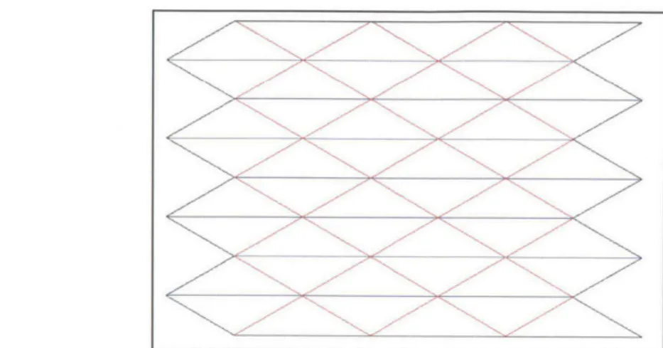
Because the spring-like origami structures compress vertically, horizontal rows of tiles move closer together as the origami is compressed. In order to create a capacitive sensor (that is, a sensor that detects changes in displacement through measuring changes in capacitance), tiles within horizontal rows needed to connect conductively to create something akin to a series of parallel plate capacitors. Tiles connect to each other through bridges, which can only connect over mountain folds. The initial design for the spring consisted of tiles connected vertically rather than horizontally. The pattern was redesigned to take advantage of conductive mountain folds, and the result is shown at in Figure 3.3 where mountain folds are depicted with red lines, and valley folds with blue.
' '
Figure 3.3 - Basic crease pattern for horizontal conduction through mountain folds. Red lines indicate
mountain folds (where conductive bridges will be located). Triangular tiles connected by these mountain folds form 8 horizontal rows of conduction.g
This new design creates 8 independent rows of tiles connected by mountain folds. A capacitive sensor was constructed by connecting alternate rows, creating the equivalent structure of an 8-parallel-plate capacitor.
An additional redesign by Miyashita included end tiles to connect alternate rows, as seen in Figure 3.4a.
3.4.1 Self-Folding
Once designed, the capacitive sensor was constructed using Miyashita's self-folding technique. As was described in chapter 2 for the resistive sensor, this technique utilizes
variations in gap width to dictate whether a crease will form a mountain or a valley fold. After construction of the flat origami pattern with appropriate gap widths, the sheet was placed into an oven and heated to between 65'C and 70'C. The folding process during heating is displayed in
(a)
(b)
measure Ctotai front face -- back face electrically connected 600C, 264S 67 C25 (C)Figure 3.4 - Manufacture of a capacitive sensor, from [12] Miyashita et. al.
3.4.2 Measurement
Once folded, the capacitance was measured between the points denoted in Figure 3.4c. As the origami is compressed, the angle between the triangular center tiles decreases, and the tiles come closer and closer together. From intuition as well as sections 3.2 and 3.3, we know that decreasing angle results in growing capacitance. This prediction was verified in Figure 3.5 which plots measured capacitance against length of the sensor (shorter length corresponds to greater compression).
Capacitance vs. Axial Length 50 -45 -40 0. 0 35 2 030 25 20 15 10 20 30 40 50 60 70 80 Axial Length (mm)
Figure 3.5 - Measurement of capacitance vs. axial length (compression) of the origami structure in
Figure 3.4. Capacitance was measured once at a number of axial lengths using a benchtop LCR meter.
Maximum compression (minimum axial length) occurs on the left-most side of the plot. This corresponds with maximum capacitance, as the angle between tiles reaches its lowest values.
4. Inductance and Magnetic Field
4.1 Motivated by Actuation
In thinking about the potential of printable actuators for otherwise printable robots, the possibility of creating a voice coil was considered. A voice coil actuator uses applied current to create magnetic field. This magnetic field interacts with the field of a donut-shaped permanent magnet placed to surround the coil. The interaction between magnetic fields causes the coil to raise and lower depending on applied current. With this general concept, an investigation into the potential usefulness of a self-folded coil was launched.
4.2 Model and Measurement of Coil Inductance
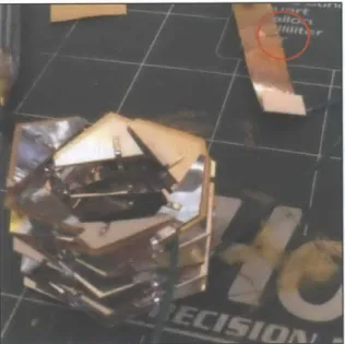
With a voice coil in mind as motivation, a hexagonal-coil was made using a similar design to the capacitive structure in the previous chapter. Though advancements in self-folding such a coil have since been made (by fellow researcher Federico Fries), initial tests were completed using hand-folded copper material to allow for higher levels of current. The basic structure of triangular tiles connected by bridges was maintained.
Figure 4.1 - A 24-winding hand-folded coil. The folded coil consists of copper material (to withstand
To model the inductance of this coil, Harold Wheeler's 1982 paper "Inductance Formulas for Circular and Square Coils," was referenced. 13
3 In this paper, Wheeler provides an equation
for inductance of a circular coil as follows:
L = 0.4n2a n (1 + + 1 [4.1]
2.3+1.6-+0.44/
a a
where
a: radius of coil b: axial length of coil n: number of turns
By modeling the hand-folded 24-winding coil as circular, dimensions (in meters, where applicable) are:
a= .008; b=.022; n = 24;
These values, when used to calculate inductance as per Wheeler's model, result in an inductance of 5.0 mH. When measured, the same coil was found to have an inductance of 4.6 mH. Though these values are quite close, differences might be explained by the use of a circular coil model on a roughly hexagonal shape (variation in measurement of the hexagon's "radius" may account for discrepancies).
4.3 Magnetic Field
Once inductance was modeled and measured, various levels of current were run through the 24-winding structure to produce magnetic field. The magnetic field was measured using a hall-effect sensor. Additional measurements were taken after placing an 11mm ferrous core within the coil to increase the magnetic field. Results of these measurements (with and without core) are shown in Figure 4.2.
Magnetic Field vs. Current of a Folded Coil
100
-0 no core
0 11 mm diameter ferrous core
60 ' 70 S60 50 140 0 1 1. 2 2.5 3 3.5 4 4.5 5 Current (amps)
Figure 4.2 - Effect of ferrous core on the magnetic field produced by a folded coil. The magnetic field of a 24-winding folded coil was measured once at several 1-amp intervals to a maximum of 5-amps. These measurements were repeated after placement of an 1 1mm diameter ferrous core within the coil to
demonstrate the core's effect on magnetic field. The ferrous core was found to approximately triple the measured magnetic field as compared to a coil with no core.
In addition to measurements of magnetic field, a physical demonstration of magnetic field was achieved by placing a small magnet (roughly 2mm in diameter) within an 8-winding hand-folded origami structure and applying a sudden 5A current. The magnet was small enough that it flipped over when exposed to such instantaneous magnetic field.
Figure 4.3 - Magnet flip caused by the magnetic field produced from a 5A current in an 8-winding hand-folded coil. A sudden current was applied to the coil, causing magnetic field in the direction of the axis running through the center of the coil. This field caused a small permanent magnet to flip in order to align
itself with the field.
4.4 Harnessing Magnetic Field for Actuated Contraction
Once the ability to produce magnetic field using folded coils was established, an attempt was made to harness this magnetic field for the purposes of actuation. By the suggestion of fellow researcher Federico Fries, a setup was constructed to take advantage of the tendency for ferrous metals to attract under exposure to magnetic field. This setup can be seen in Figure 4.4.
(a) (b) 28.0
top and bottom ends of cylinders
compressible are suspended to the coil
rigami coil coil contraction1
1
17.2 ... 22.4 N iron ~magnetization cylinders attraction (bolts) 29 25.4 61 29.6 10.5coil power off coil power on
Figure 4.4 - Setup for the contraction of a hand-folded coil via attraction between two ferrous cores.
Bolts (shown in dark grey) were used as the cores for their availability and relatively cylindrical shape. Dimensions in 4.4(b) are given in millimeters.
As current through the coil increases, magnetic field grows stronger and the two ferrous cores (in this case, bolts) attract each other. This force causes contraction of the coil, as seen in Figure 4.5.
0.9 0.8 F 0.7 0.61[ E E 0 0 measur fit 01 1 1.5 2 2.5 3 Current [A] 3.5 4 4.5 5
Figure 4.5 - Measured contraction of a coil at various currents using the setup shown in Figure 4.4. Contraction of the 24-winding origami (in mm) is plotted against applied current (amps). As current increased, so did magnetic field and attractive force between the two iron cores. A small contraction can be seen in the images at top left. Measurements of contraction were taken by filming using an HD digital camera and image processing software.
0.5 0.4 0.3 0.2 0.1 arments
5.
Conclusions and Future Work
5.1 Conclusions
As part of a larger goal toward achieving entirely printable robots, work was undertaken to address the need for printable sensors and actuation. Using Miyashita's method for
self-folding origami, a number of conductive, self-folded structures were designed and manufactured. By utilizing the inherent resistance of the metallized polyester film used to make the origami,
two resistive sensors (one, a switch-style and the other with several discrete states), were
constructed. To achieve a smoother gradient for sensing variations in compression, a new pattern was designed for the purposes of capacitive sensing. This capacitive sensor succeeded in
detecting changes in length of the physical structure. Lastly, the inductance and magnetic field of a folded coil were investigated, along with the potential for a foldable actuator. Magnetic field was successfully produced in a folded coil through application of current. This field was harnessed to "flip" a small permanent magnet, as well as to produce actuated contraction of a coil using attraction between ferrous cores.
5.2 Future Work
Though these advancements do contribute to the goal of more printable robotics, there is still work to be done. The capacitive sensor described is capable of measuring changes in displacement, but if the physical properties of the structure were characterized (mainly, the
spring constant), measuring these changes in capacitance could also be used to measure an applied force. Additionally, into improving the manufacturing process could prove useful. As it currently stands, only the adhesive and MPF materials can be cut with a laser, but the shrinking layer made of PVC must be manually cut for safety reasons. Reducing the number of manual
steps in the fabrication process would move the self-folding origami closer to being truly printable.
Further, all coils described in the inductance and magnetic field section were hand-folded. To produce magnetic field, each coil required more current than the MPF material could withstand and copper material (not self-foldable) had to be used instead. More research could be done to produce small-diameter, self-folded MPF coils. With small enough diameter and
sufficient windings, a lower current could produce the same results as described in this thesis. Additionally, further research into materials could improve coil performance. A material both flexible and highly conductive could produce self-folded coils capable of handling high levels of current. A new shrinking material capable of being laser-cut could prove quite valuable.
5.3 Lessons Learned
During the research involved for this thesis, I learned several key lessons: " Proper and safe use of a laser cutter
I learned how to safely and appropriately operate a CO2 laser cutter to cut and etch
using both raster and vector settings. Safe operation requires that the operator closely watch the machine while it is cutting - no leaving it alone! Metals cannot be cut in the laser cutter. Cutting a material which contains chlorine can release a dangerous gas, and should not be done. In addition to safety measures, I learned the hard way that it's a good idea to cut a small test piece to make sure settings are correct before moving on to the main piece. This saves time and material in the long run.
Fabrication of the origami often required delicately peeling off adhesive backing and using an x-acto knife to cut away material at the edges as well as PVC film within a pattern. Making a large number of origami pieces improved my manual dexterity and taught me that slow, methodical cutting and peeling is always preferable. One small mistake can cost hours of work. Additionally, I became familiar with working under a
microscope with tweezers to produce a few especially small pieces of origami.
Keep the larger picture in mind
In producing the variety of origami pieces for this thesis, a significant amount of time was spent on detailed tasks, like the cutting and peeling described above. I found it easy to get lost in these tasks, becoming concerned with getting a particular model to self-fold without thinking of how important that particular design was to the larger picture. I learned to spend time considering the merits of a particular design and its place within the larger goal, before spending too much time on the details of fabrication.
6. Appendices
Appendix A.
R-A = .0291/.140;
RB = .0285/.140;
Rs = 1; % An initial guess for Rs
expression = exp(-pi*RA/RS)+exp(-pi*RB/Rs); while abs(1-expression)>=.00001 if 1-expression >= .00001 Rs = Rs+.000001; elseif 1-expression <= -.00001 Rs = Rs-.000001; else Rs = Rs; end expression = exp(-pi*R..\/RS)+exp(-pi*RB/Rs); end
7.
References
[1] N. Benbernou, E.D. Demaine, M.L. Demaine, and A. Oyadya, "A universal crease pattern for folding orthogonal shapes," arXiv:0909.5388, 2009.
[2] E. Hawkes, B. An, N. M. Benbernou, H. Tanaka, S. Kim, E. D. Demaine, D. Rus, and R. J. Wood, "Programmable matter by folding," Proceedings of the National Academy of
Sciences, vol. 107, no. 28, pp. 12441-12445, 2010.
[3] J.K. Paik, R.K. Kramer, and R.J. Wood "Stretchable Circuits and Sensors for Robotic Origami," Proceedings of the IEEE/RSJ International Conference on Intelligent Robots
and Systems (2011): 414-420.
[4] J.W. Judy and R.S. Muller, "Magnetically actuated, addressable microstructures,"
Journal ofMicroelectromechanical Systems, vol. 6, no. 3, pp. 249-256, 1997.
[5] Y.W. Yi and C. Liu, "Magnetic actuation of hinged microstructures," Journal of
Microelectromechanical Systems, vol. 8, no. 1, pp. 10-17, 1999.
[6] H. Okuzaki, T. Saido, H. Suzuki, Y. Hara, and H. Yan, "A biomorphic origami actuator fabricated by folding a conducting paper," Journal ofPhysics: Conference Series 127 (2008): 012001.
[7] C.D. Onal, R.J. Wood, and D. Rus, "Towards Printable Robotics: Origami-Inspired Planar Fabrication of Three-Dimensional Mechanisms," Proceedings of the IEEE
International Conference on Robotics and Automation (2011): 4608-4613.
[8] S.M. Felton, M.T. Tolley, C.D. Onal, D. Rus, and R.J. Wood, "Robot self-assembly by folding: A printed inchworm robot," Proceedings of the IEEE International Conference
on Robotics and Automation (2013): 277-282.
[9] S. Miyashita, C.D. Onal, and D. Rus, "Self-pop-up Cylindrical Structure by Global Heating." Proceedings of the IEEE/RSJ International Conference on Intelligent Robots
and Systems (2013): 4065-4071.
[10] C.C. Min and H. Suzuki, "Geometrical properties of paper spring," Manufacturing
Systems and Technologies for the New Frontier (2008): 159-162.
[11] L.J. van der Pauw, "A Method of Measuring the Resistivity and Hall Coefficient on Lamellae of Arbitrary Shape." Philips Technical Review (1958/59, No. 8): 220-224. [12] S. Miyashita, L. Meeker, M. G6ldi, Y. Kawahara, and D. Rus, "Self-Folding Printable
Elastic Electric Devices: Resistor, Capacitor, and Inductor."
[13] H. A. Wheeler, "Inductance Formulas for Circular and Square Coils," Proceedings of the


![Figure 3.4 - Manufacture of a capacitive sensor, from [12] Miyashita et. al.](https://thumb-eu.123doks.com/thumbv2/123doknet/14734093.573750/29.918.183.724.100.755/figure-manufacture-capacitive-sensor-miyashita-et-al.webp)

