Département de génie électrique et de génie informatique
Optimisation de la Conception du Moteur
Synchrone à Excitation Hybride pour Véhicules
Électriques à Haut Performance
Design Optimization of
Hybrid Excitation Synchronous Motor
for Electric Vehicles with Enhanced Performance
Thèse de doctorat
Spécialité : génie électrique et informatique
Ahmad Shah Mohammadi
Jury : João Pedro F. TROVÃO (directeur)
Minh CAO TA
Carlos HENGGELER ANTUNES
Ahmed KHOUMSI
Emmanuel VINOT
M
EMBRES DU JURY
M. João Pedro F. TROVÃO, Directeur
Professeur Agrégé, Université de Sherbrooke (UdeS), QC, Canada
M. Minh C. Ta, Évaluateur
Professeur Associé, Hanoi University of Science and Technology
(HUST), Vietnam
M. Carlos Henggeler Antunes, Évaluateur
Professeur Titulaire, University of Coimbra, Portugal
M. Ahmed Khoumsi, Rapporteur
Professeur Titulaire, Université de Sherbrooke (UdeS), QC, Canada
M. Emmanuel Vinot, Évaluateur
Chargé de recherche, HDR, Institut français des sciences et
technologies des transports, de l'aménagement et des réseaux
iv
“The best way to know a city is to get lost in it.”
Acknowledgements
I would like to thank my supervisor, prof. João Pedro F. TROVÃO, for his guidance and support through each stage of the process, and also for giving me this great opportunity. This work was supported in part by Canada Research Chairs Program (grant 950-230672),
I would like to acknowledge the respectful jury members for their constructive comments and also their commitment that helped me present my work on the due date.
I would like to thank the staff at university of Sherbrooke, especially, the e-TESC lab members, for helping me to finalize this project. I wish to extend my special thanks to Mr. Mebrahtom Beraki for his wonderful support and friendship during my journey.
My wife, Zahra Akbari, was supportive and harmonious in the path of my research. For this, I am extremely grateful. I also appreciate the overwhelming support of my family back in Iran and here in Québec, especially Madame Lucile Paré Soucy.
Résumé
Depuis 1970, les préoccupations de l’humanité envers les changements climatiques ont poussé les chercheurs à faire des études approfondies pour optimiser les machines électriques pour avoir des véhicules électriques plus performants et moins énergivores. La conception optimale de véhicules électriques (EV) peut contribuer pour un marché automobile plus exigeant et jouer un rôle principal pour le futur du transport durable des biens et des personnes. Les machines électriques se trouvent au cœur de la conversion d'énergie électromécanique, qui ont suscité beaucoup d'intérêts et d’efforts pour augmenter leur rendement et réduire leur coût.
Cette thèse propose une méthodologie et une mise en œuvre pour minimiser le coût et maximiser l’efficacité d’une machine synchrone à excitation hybride (HESM) pour un véhicule donné et un cycle de conduite sélectionné. L'hybridation du système d’excitation peut combiner les qualités favorables comme un couple élevé à basse vitesse avec une capacité de surcharge supérieure, un défluxage exceptionnelle et une plage de vitesse prolongée de puissance constante (CPSR), une efficacité élevée et une contrôlabilité flexible dans les modes de traction et de freinage régénératif. Avec la technologie HESM, nous pouvons également passer des aimants de terres rares aux aimants en ferrite bon marché, et garantir l’approvisionnement pour l’industrie automobile.
Le HESM conçu dans ce travail répond à trois exigences du véhicule : la vitesse de croisière maximale, le temps d’accélération et la capacité de monter une pente, avec un surdimensionnement minimal ou nulle de la chaîne de traction. Une optimisation multiniveau avec une interaction entre la vision composant et la vision système est proposée et validée. L’optimisation au niveau du composant est développée sur la base de l’algorithme génétique de tri non dominé (NSGA-II). Une nouvelle formulation pour les fonctions objectives est proposée pour l’optimisation simultanée de la conception de la machine et de la minimisation de son coût. Après avoir optimisés onze HESM au niveau du composant, pour maximiser l’efficacité, une optimisation au niveau du système est réalisée pour trouver le HESM optimal avec le plus haut rendement global sur le cycle de conduite donné. Une validation de la conception finale de la HESM présente un meilleur rendement global sur le cycle de conduite de 18,65% en relation à une machine synchrone à excitation séparée équivalente et 15,8% en relation à une à aiment permanent.
En raison de la direction 3D du flux magnétique dans la topologie HESM sélectionnée, l’analyse par éléments finis (FEA) prenait beaucoup de temps et de ressources computationnelles. Afin d’évaluer les fonctions objectives lors de l’optimisation, un nouveau modèle a été développé basé sur un réseau de circuits magnétiques équivalents 3D (MEC). Ce modèle prédit bien la non-linéarité des matériaux magnétiques, par rapport aux simulations FEA. Enfin, le HESM optimisé final est évalué grâce à la technique FEA.
viii
Mots clés:
Plage de vitesse de puissance constante, méthodologie de conception véhicule électrique, analyse par éléments finis, efficacité globale, moteur synchrone à l’excitation hybride, rapport d’hybridation, circuit équivalent magnétique, l'algorithme génétique de tri non dominé (NSGA-II), optimisation.
Abstract
Since 1970, the ever-growing concerns of human community for the life-threatening environmental changes have pushed the policy makers to decarbonize those sectors with high energy demands, including the transportation industry. Optimal designs of Electric Vehicles (EVs) can contribute to today’s exigent car market, and take the leading role for future sustainable transportation of human and goods. At the heart of electromechanical energy conversion lays the electrical machines, which have attracted lots of interests and efforts for efficiency increase and cost reduction.
In this thesis, a methodology is proposed and implemented to design and optimize the cost and efficiency of a Hybrid Excitation Synchronous Machine (HESM) for a given vehicle and a desired driving cycle. Hybridization in the excitation system can combine the favorable qualities of high-torque at low-speed with superior overloading capability, exceptional flux weakening and extended Constant Power Speed Range (CPSR), high efficiency, and flexible controllability in motoring and generation modes. With HESM technology, we can also shift from the rare-earth magnets towards the cheap ferrite magnets and guaranty the supply for motor industry.
The designed HESM in this work responds to three requirements of the vehicle, namely, the maximum cruising speed, acceleration time, and gradeability, with the least or null overdesign in the drivetrain. At the same time, it will have the maximum global efficiency over the driving cycle, and the minimum cost for the material. The optimization is conducted at either of the component and system levels. The optimization at component-level is developed based on the Non-dominated Sorting Genetic Algorithm-II (NSGA-II). A new formulation for the objective functions is proposed, which deals with the design optimization and cost minimization, simultaneously. To maximize the efficiency, a system-level search is conducted to find the optimum HESM with the highest global efficiency over a given driving cycle.
Due to the 3D direction of magnetic flux in the selected HESM topology, the Finite Element Analysis (FEA) was very time- and process-consuming. To be able to evaluate the objective functions during the optimization, a new model has been developed based on a 3D Magnetic Equivalent Circuit (MEC) network. This model predicts well the non-linearity of magnetic materials, as compared with the FEA simulations. At last, the final optimized HESM is evaluated by the virtue of FEA technique.
Keywords:
Constant Power Speed Range (CPSR), Design Methodology, Electric Vehicle (EV), Finite Element Analysis (FEA), Global Efficiency, Hybrid Excitation Synchronous Motor (HESM), Hybridization Ratio (HR), Magnetic Equivalent Circuit, Non-dominated Sorting Genetic Algorithm II (NSGA-II), Optimization.
Table of contents
Table of contents ... xi Introduction ... 25 Chapter 1 Global context ... 25 1.11.1.1 Electric vehicles: why and not yet in large scale? ... 25 1.1.2 Electric motor contributions to large scale penetration ... 28 1.1.3 Requirements of a perfect Electric Motor for EV ... 28 1.1.4 Why this thesis inside the Canada Research Chair in Efficient Electric Vehicles with Hybridized Energy Storage Systems ... 30
The concept of optimal Hybridization Ratio (HR) ... 30 1.2 Original contribution ... 33 1.3 Thesis outline ... 34 1.4 Conclusion ... 34 1.5
Literature Review on Design, Modelling, Optimization, and Control of Hybrid Chapter 2
Excitation Synchronous Machines (HESMs) for Electric Vehicles ... 37 Hybridization of electrical machines ... 37 2.1
HESM configurations and topologies ... 39 2.2
2.2.1 Selected topology of HESM ... 44 HESM modelling and analysis ... 45 2.3 HESM optimization ... 46 2.4 HESM control ... 47 2.5 Conclusion ... 49 2.6
Proposal and Methodology ... 51 Chapter 3
Abstract ... 52 3.1
Introduction ... 52 3.2
Problem statement and HESM as a solution ... 53 3.3
3.3.1 Overdesign problem statement ... 54 3.3.2 HESM as the solution to overdesign problem ... 56 Search algorithm to find the optimal HR ... 64 3.4
Results and discussions ... 66 3.5
Conclusion ... 69 3.6
xii Table of contents
HESM Optimization: Component Level ... 71
Chapter 4 Abstract ... 72
4.1 Introduction ... 72
4.2 Definitions and problem statement ... 74
4.3 4.3.1 HESM under study and the target variables ... 74
4.3.2 Design complexity: Soft and hard saturation in HESM ... 76
4.3.3 Comprehensive definition of Hybridization Ratio (HR) ... 78
Design optimization formulation ... 81
4.4 4.4.1 Decision Variables ... 81
4.4.2 HESM model to calculate the objective functions ... 81
4.4.3 The definition of Objective Functions (OFs) ... 82
4.4.4 Sensitivity Analysis (Taguchi Method)... 84
4.4.5 The optimization algorithm ... 88
Optimization results ... 89
4.5 Conclusion ... 92
4.6 HESM Optimization: System Level ... 93
Chapter 5 Abstract ... 94
5.1 Introduction ... 94
5.2 Definitions and problem statement ... 96
5.3 5.3.1 System under study ... 96
5.3.2 HESM design optimization for a target HR ... 98
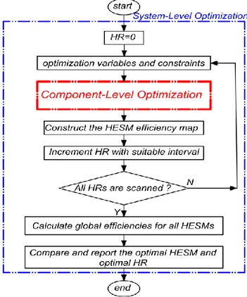
5.3.3 The proposed methodology ... 102
HESM MEC modelling and evaluation ... 104
5.4 5.4.1 MEC system of equations ... 104
5.4.2 MEC meshing ... 106
5.4.3 Magnetic material non-linearity ... 109
5.4.4 FEA validation of MEC model ... 112
Optimization results and discussions ... 114
5.5 Conclusion ... 118
5.6 Appendix (Chapter 5) ... 119
5.7 Conclusions and Future Directions ... 121
Chapter 6 Conclusions ... 121
6.1 Future Works Suggestion ... 122 6.2
Conclusion (in French) ... 124 6.3
Appendix I. Electric Motors Evaluation ... 127 Appendix II. Comparison of Modeling Techniques for Electric Machines ... 143 Appendix III.Small Scale Prototype Design ... 157 References 177
xiv List of figures
List of figures
Figure 1-1: Annual global CO2 emissions to 2017, with the 2018 projection [1] ... 26
Figure 1-2: global CO2 emissions by sector (adopted from [2]) ... 26
Figure 1-3: comparison of power and energy density for current ESS solutions [11], and [12] ... 28
Figure 1-4: Ideal and real traction motor ... 29
Figure 1-5: Position of the thesis within Canada Research Chair program in e-TESC lab .... 30
Figure 1-6 Moving the high-efficient area of HESM as a function of HR over EMPA-C2 driving cycle... 32
Figure 1-7 Moving the operating points as a function of gearbox (GB) ratio for HR=0 ... 33
Figure 2-1 HESMs with both PM and WE on the rotor ... 40
Figure 2-2 HESMs with both PM and WE on the stator ... 40
Figure 2-3 Series HESM [59] ... 41
Figure 2-4 Parallel HESM, both excitations on the rotor ... 41
Figure 2-5 Parallel HESM, PM excitations on the rotor and WE on the stator ... 42
Figure 2-6 FSHESM, PM and WE on the stator ... 43
Figure 2-7 New FSHESM with a global excitation winding [53] ... 44
Figure 2-8 Selected HESM topology with minor modifications: 1- PMs (ferrite), 2-rotor claws (iron–silicon alloy), 3- stator coils (copper), 4- stator (silicon steel lamination), 5-outer stator (iron–silicon alloy), 6-WE coils (copper) ... 45
Figure 2-9 Optimization algorithms used for design of electrical machines (based on [89]). 46 Figure 2-10 Typical structure of an optimization process (based on [93]). ... 47
Figure 3-1: global Specifications and requirements of the three-wheel vehicle [117] ... 54
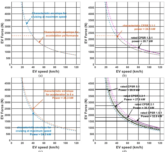
Figure 3-2: Drivetrain overdesign problem due to limited CPSR (a), (b) cruising at maximum speed is dominant, (c), (d) acceleration criterion is dominant ... 55
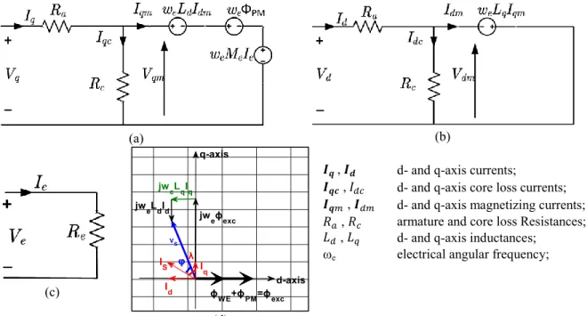
Figure 3-3: HESM first harmonic steady-state circuit model: (a), (b) q- and d-axis model, respectively, (c) WE system model, (d) dq reference frame ... 57
Figure 3-4:HESM normalized parameters and three dimensional cut view [116] ... 58
Figure 3-5 HESM operating modes, constant torque and constant power ... 59
Figure 3-6 HESM dq representation at rated condition ... 60
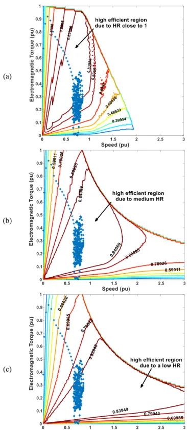
Figure 3-7 High efficient area move due to HR change, operating points for EMPA.C-2: (a) HESM with HR=1, η=83.3%, (b) HESM with HR=0.72, η=87.1%, (c) HESM with high HR=0.51, η=85.1%. ... 63
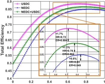
Figure 3-9 Efficiency maps and driving cycles operating points at optimal HRs: a) UHDC,
(b) NEDC, (c) UHDC+ NEDC. ... 67
Figure 3-10 Global efficiency of HESM as a function of HR for different driving cycles .... 68
Figure 4-1: Global efficiency over EMPA-C2 driving cycle as a function of HR. ... 73
Figure 4-2: Component-level optimization as part of HESM system-level optimization (for details about the component-level optimization, see Figure 4-9). ... 74
Figure 4-3: HESM under study with 3D flux directions... 75
Figure 4-4: Interactions of PM and WE flux paths in flux weakening ... 77
Figure 4-5: FEA simulation of soft and hard saturation phenomenon ... 78
Figure 4-6: Airgap flux density (𝐵𝑎𝑔) and average relative permeability of the outer stator (𝜇𝑟) as a function of WE current at no-load (zero armature current) ... 79
Figure 4-7: Different possible error values and the dominant mode ... 81
Figure 4-8: The effect of variables on the OFs by analysis of levels ... 85
Figure 4-9: Flow chart of proposed optimization method ... 88
Figure 4-10: The Pareto optimal front ... 89
Figure 4-11: FEA evaluation of the final HESM: (a) Flux regulation capability of the final HESM (phase-A), (b) Voltage regulation capability of the final HESM (phase-A), (c) Average nominal torque for the final HESM. ... 91
Figure 5-1: Changing the place of highly-efficient area as a function of HR... 95
Figure 5-2: HESM under study with 3D flux directions... 97
Figure 5-3: NSGA-II results for an arbitrarily-selected HR (HR=0.3) ... 102
Figure 5-4: Proposed methodology for multilevel optimization of HR in HESM ... 103
Figure 5-5 Armature coils MMF distribution ... 106
Figure 5-6: HESM sections in: a) XY plane b) Z direction ... 107
Figure 5-7: A generic mesh element ... 108
Figure 5-8: Non-linear MEC solving ... 110
Figure 5-9: BH curve for M-19 29Ga (source: MagNet Infolytica) ... 110
Figure 5-10: Error minimization algorithm (i: index of mesh element) ... 111
Figure 5-11: MEC Evaluation: flux density at different excitation currents ... 112
Figure 5-12: Evaluation: rated flux linkage, voltage, and cogging torque ... 113
Figure 5-13: Specified and calculated d-axis flux linkages as a function of HR ... 115
Figure 5-14: Normalized design variables and Cost ($ US) as a function of HR ... 116
Figure 5-15: Normalized dq parameters as a function of HR ... 117
Figure 5-16: Global efficiency over US06 driving cycle as a function of HR ... 117
xvi List of figures
Figure A.I. 1 Three-wheel roadster example ... 129
Figure A.I. 2 Ideal and real traction motor ... 130
Figure A.I. 3 Proposed flowchart for EV T-S envelope definition ... 132
Figure A.I. 4 𝑃𝑚𝑎𝑥 resulted from needed Vmax ... 133
Figure A.I. 5 Increase in EV 𝑃𝑚𝑎𝑥 due to acceleration requirement ... 134
Figure A.I. 6 𝑃𝑚𝑎𝑥 of EV due to a motor with limited CPSR... 134
Figure A.I. 7 Efficiency routine flowchart ... 135
Figure A.I. 8 Inverse distance weighted interpolation from test data mesh-grid ... 136
Figure A.I. 9 EV 𝑃𝑚𝑎𝑥 at different steps of the proposed algorithm ... 138
Figure A.I. 10 EV 𝑃𝑚𝑎𝑥 reduction due to increase in motor CPSR ... 138
Figure A.I. 11 First motor NEDC operating points on efficiency map ... 139
Figure A.I. 12 Second motor NEDC operating points on efficiency map ... 139
Figure A.I. 13 First motor USDC operating points on efficiency map... 140
Figure A.I. 14 Second motor USDC operating points on efficiency map ... 140
Figure A.II. 1 Designed PMSM (1-stator, 2-rotor, 3-PMs, 4-armature coils) ... 146
Figure A.II. 2 The PMSM Efficiency map, constructed by FEA ... 147
Figure A.II. 3 PMSM first-harmonic steady-state D-Q circuit model ... 149
Figure A.II. 4 (a) Stator, airgap, and rotor mesh (b) a generic mesh element ... 150
Figure A.II. 5 2D MEC model evaluation: a) flux density, b) flux linkage, and c) no-load back EMF ... 151
Figure A.II. 6 2D MEC model average torque evaluation ... 152
Figure A.II. 7 Efficiency map calculated by a) DQEC and b) MEC ... 153
Figure A.II. 8 Efficiency map error for DQEC (narrow bars) and MEC (wide bars) compared to FEA ... 154
Figure A.II. 9 Error for a) copper loss, b) core loss, and c) output power with DQEC (narrow bars) and MEC approach (wide bars) compared to FEA (reference) ... 154
Figure A.III. 1 EV characteristic and rated (PMSM) envelopes for Spyder (dashed lines are the power levels) ... 158
Figure A.III. 2 Test plan for the HESM prototype ... 159
Figure A.III. 3 MAGTROL dynamometer torque-speed envelope (grey: continuous, black: peak) ... 160
Figure A.III. 4 HESM global view: 1- PMs (ferrite), 2-rotor claws (iron–silicon alloy), 3- stator coils (copper magnetic wire ), 4- stator (Fe-Si laminations), 5-outer stator (iron–silicon
alloy), 6-WE coils (copper magnetic wire) ... 164
Figure A.III. 5 HESM cross sections of S-pole (top) and N-pole (bottom)... 164
Figure A.III. 6 HESM rotor (a) sections, (b) assembly with PMs ... 165
Figure A.III. 7 Rotor construction dimensions at XY plane ... 166
Figure A.III. 8 Rotor S-pole cross section at YZ plane (a) global view (b) Details 1 ... 167
Figure A.III. 9 Hybrid deep groove ball bearing (a) global view (b) side view ... 170
Figure A.III. 10 lamination drawing details for cutting (a) global view (b) stator slot ... 173
Figure A.III. 11 HESM stator (a) laminations stack (b) WE coils assembled ... 174
xviii List of tables
List of tables
Table 3-1 Studied driving cycles ... 64
Table 3-2 Global efficiency at optimal HR... 68
Table 3-3 comparing motors for combined driving cycle ... 68
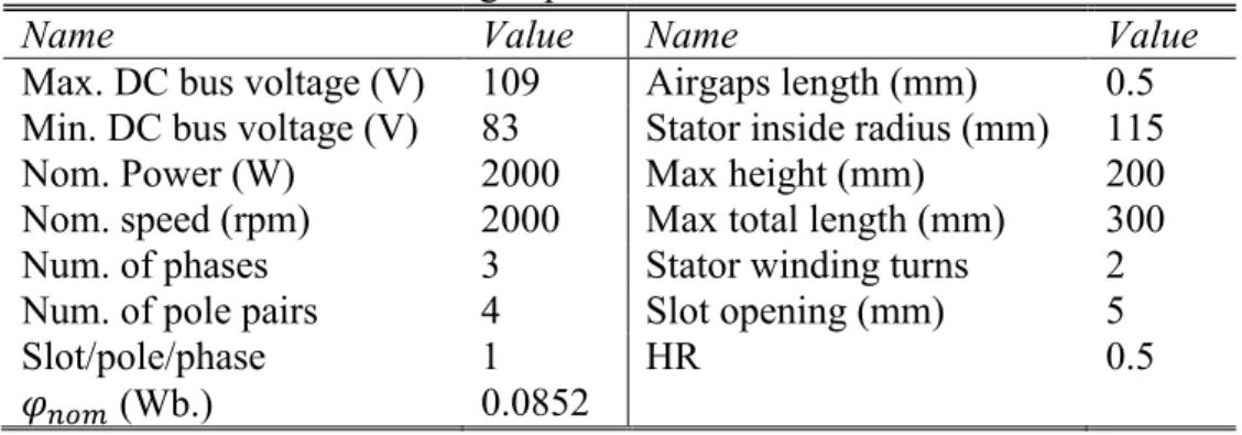
Table 4-1 design specifications and constraints... 76
Table 4-2 Optimization Variables (see Figure 4-3) ... 76
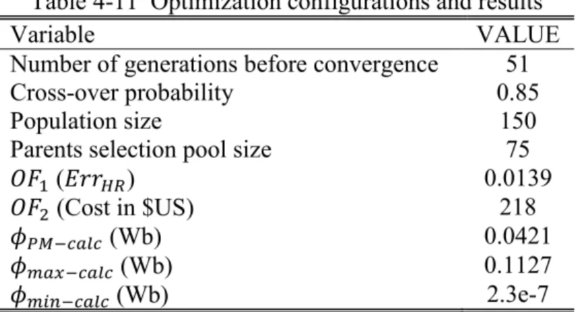
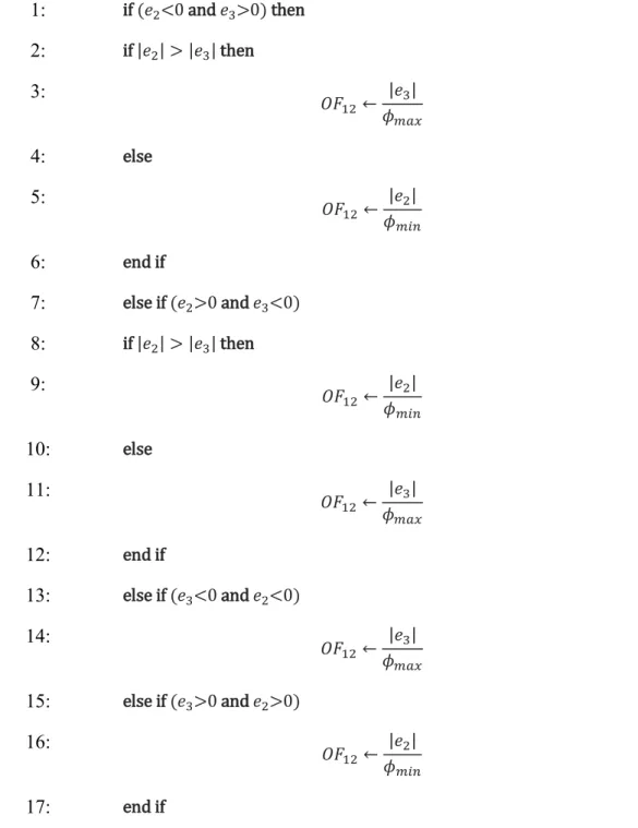
Table 4-3 Pseudo-code for the calculation of second term in 𝐸𝑟𝑟𝐻𝑅 (𝑂𝐹12) ... 83
Table 4-4 Price/m3 of different materials in the HESM* ... 84
Table 4-5 Variables and levels ... 84
Table 4-6 Optimal level of each variable ... 85
Table 4-7 ANOVA for 𝑂𝐹1 ... 86
Table 4-8 ANOVA for 𝑂𝐹2 ... 87
Table 4-9 Decision Variables ... 87
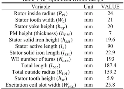
Table 4-10 Optimized HESM design ... 90
Table 4-11 Optimization configurations and results ... 92
Table 5-1 The specifications of EV under study ... 98
Table 5-2 design specifications and constraints... 98
Table 5-3 Design Variables ... 99
Table 5-4 Price/m3 of different materials in the HESM* ... 101
Table 5-5 Pseudo-code for the calculation of second term in 𝐸𝑟𝑟𝐻𝑅 (𝑂𝐹12) ... 119
Table 5-6 Optimized HESM design ... 120
Table 5-7 Mesh and solver configurations ... 120
Table A.I. 1 Specification and requirement of the three-wheel roadster prototype 8 ... 131
Table A.I. 1 Specification and requirement of the three-wheel roadster prototype 8 ... 131
Table A.I. 2 Efficiency results ... 141
Table A.II. 1 The PMSM dimensions and materials ... 146
Table A.II. 2 FEA model configuration ... 147
Table A.II. 3 PMSM d-q parameters ... 148
Table A.II. 5 Norm of the error matrix ... 155
Table A.II. 6 FEA, DQEC, and MEC comparison ... 155
Table A.III. 1 Spyder design specifications ... 157
Table A.III. 2 Rated values of the existing PMSM... 158
Table A.III. 3 Spyder expected performance ... 158
Table A.III. 4 MAGTROL dynamometer specifications ... 160
Table A.III. 5 dynamometer limits for different base speeds ... 161
Table A.III. 6 dynamometer-limited motor absolute maximum ratings ... 161
Table A.III. 7 Inverter and excitation converter rated values ... 161
Table A.III. 8 DC bus specifications ... 162
Table A.III. 9 Inverter’s continuous and peak currents ... 162
Table A.III. 10 Inverter-limited motor absolute maximum ratings ... 162
Table A.III. 11 final HESM absolute maximum ratings ... 163
Table A.III. 12 Optimized HESM design ... 163
Table A.III. 13 Properties of rotor magnetic material: FeSi3P (from VALBRUNA Group) ... 168
Table A.III. 14 Properties of Ferrite PM: Ceramic 10 ... 169
Table A.III. 15 Properties of shaft material: AISI Type 304 stainless steel ... 169
Table A.III. 16 Bearing specifications for 6008-2RZTN9/HC5C3WT ... 171
Table A.III. 17 Specifications of Stator Fe-Si sheets... 172
xx Nomenclature/Symbols
Nomenclature/Symbols
Abbreviations ANOVA Analysis of Variance
CPSR Constant Power Speed Range
CVT Continuously Variable Transmission d.f. degree of freedom
DQEC D-Q lumped parameter Equivalent Circuit DSPMM Doubly Salient Permanent Magnet Machine
DTC Direct Torque Control EM Electric Motor
EMF ElectroMotive Force
EMR Energy Macroscopic Representation Err_HR Error in HR
ESS Energy Storage System
e-TESC Transport, Energy Storage and Conversion EV Electric Vehicles
FEA Finite Element Analysis F-S Force–Speed
FSHESM Flux Switching Hybrid Excitation Synchronous Machine FW Flux Weakening
GB Gear Box
HESM Hybrid Excitation Synchronous Machine HESS Hybridized Energy Storage Systems
HR Hybridization Ratio
ICE Internal Combustion Engine IEA International Energy Agency
IM Induction Machine
IPM Internal Permanent Magnet MEC Magnetic Equivalent Circuit MMF Magnetomotive Force
MS mean square
MTPA Maximum Torque per Ampere MTPV Maximum Torque per Voltage NEDC New European Driving Cycle
NSGA-II Non-dominated Sorting Genetic Algorithm - II OF Objective Function
PM Permanent Magnet
PMSM Permanent Magnet Synchronous Machine PU Per-Unit
RM Reluctance Machine RPM Round Per Minute
SPMSM Surface-mounted Permanent Magnet Synchronous Machine
SRM Switched Reluctance Machine SS sum of squares
T-S torque-speed
UHDC US Highway Driving Cycle
US06 Supplemental Federal Test Procedure
WE Wound Excitation
WESM Wound Excitation Synchronous Machine Symbols
𝐴𝑓 Vehicle front area 𝐵 Magnetic flux density 𝐵𝑎𝑔 Airgap flux density
𝐶𝐷 Aerodynamic drag coefficient 𝑓 frequency
𝑓𝑟 Rolling resistance coefficient
𝐹𝑡−𝑉𝑚𝑎𝑥 tractive force at maximum cruising speed 𝑔 Acceleration of gravity, Radial airgap 𝑔𝑒𝑥𝑐 Horizontal airgap
𝑔𝑡 Gearbox transmission ratio 𝐻 Magnetic field intensity ℎ𝑠𝑦 stator yoke height
ℎ𝑠𝑡 Stator tooth height ℎ𝑃𝑀 PM height (thickness) ℎ𝑠𝑠𝑖 Outer stator solid iron height
i Grade Slope at 100 km/h
𝐼 current
𝐼𝑒 excitation current 𝐼𝑞 , 𝐼𝑑 d- and q-axis currents
𝐼𝑞𝑐 , 𝐼𝑑𝑐 d- and q-axis core loss currents 𝐼𝑞𝑚 , 𝐼𝑑𝑚 d- and q-axis magnetizing currents
𝐾𝑓 excitation coefficient 𝑙𝑡𝑜𝑡 Total motor length
𝑙𝑠 stator active length
𝑙𝑠𝑠𝑖 Outer stator end cap length 𝑙𝑠−𝑙𝑎𝑚 Stator stack lamination length 𝐿𝑑 , 𝐿𝑞 d- and q-axis inductances
M Vehicle mass
𝑀𝑒 mutual inductance between WE and armature coils 𝑀𝑀𝐹𝑊𝐸 WE Magnetomotive Force
𝑁 Speed, number of coil turns
𝑁𝑏 Base Speed 𝑁𝑚𝑎𝑥 Max Speed
𝑁𝑒𝑥𝑐 WE coils number of turns 𝑁𝑠 armature coils number of turns
xxii Nomenclature/Symbols
𝑃 Power, price, permeance
𝑃𝑚𝑎𝑥 maximum power
𝑃𝐹𝑒𝑆𝑖 silicon steel sheets price 𝑃𝐹𝑒 Iron–silicon alloy price 𝑃𝑃𝑀 PM material price
𝑃𝑠ℎ shaft material price
𝑃𝑐𝑢 copper losses, or copper magnetic wire price 𝑃𝑐 core losses
𝑅𝑡𝑜𝑡 Total outside radius
𝑅𝑎 , 𝑅𝑐 , 𝑅𝑒 armature, core loss, and excitation resistances 𝑟𝑑 Wheels radius
𝑅𝑟𝑖 Rotor inside radius 𝑅𝑟𝑜 Rotor outside radius 𝑆𝑠𝑙𝑜𝑡 total stator slot area
𝑇 torque
𝑇𝑒 electromechanical torque 𝑡𝑎 Acceleration Time
𝑉 Voltage, volume, linear velocity 𝑉𝑚𝑎𝑥 Maximum Speed
𝑉𝑎𝑐𝑐 Acceleration Speed 𝑽𝒒 , 𝑽𝒅 d- and q-axis voltages
𝑉𝑟𝑎𝑡𝑒𝑑 rated speed
𝑊𝑒𝑥𝑐 Excitation coil slot width 𝑊𝑡 stator tooth width
𝑊𝑃𝑀 PM width
Greek symbols
𝜂 efficiency
𝜂𝑡 Gearbox efficiency 𝜂𝑔𝑙𝑜𝑏𝑎𝑙 Global efficiency
𝛿1 tolerance for norm of error in permeability matrix 𝛿2 tolerance for error in elements of permeability matrix 𝜙𝑛𝑜𝑚 nominal d-axis flux linkage
𝜙𝑒𝑥𝑐 excitation flux 𝜙𝑃𝑀 PM flux 𝜙𝑊𝐸 WE flux
𝜑𝑑 d-axis flux linkage 𝜙𝑚𝑖𝑛 minimum excitation flux 𝜙𝑚𝑎𝑥 maximum excitation flux
ω𝑒 electrical angular frequency 𝜌𝑎𝑖𝑟 Air density at 15°C
ℛ Reluctance
𝜇𝑟 relative permeability 𝜇0 Vacuum permeability
𝜃𝑚 Mechanical angle 𝜃𝑒 electrical angle
𝜆 current angle with respect to EMF vector indices 𝑐𝑎𝑙𝑐 calculated 𝑚𝑎𝑥 maximum 𝑚𝑖𝑛 minimum 𝑛 normalized 𝑖𝑛 input 𝑜𝑢𝑡 output 𝑎𝑣𝑒 average 𝑐𝑜𝑛 continuous 𝑝𝑘 peak 𝑎𝑐 or 𝐴𝐶 Alternative current 𝑑𝑐 or 𝐷𝐶 Direct current 𝑎𝑔 airgap 𝑠𝑎𝑡 saturation
Introduction
Chapter 1
This chapter is meant to discuss the global context, the outlines, and the original contributions of this thesis. Under the global context, the existing problem of conventional transportation is briefly scanned and the possible solutions are mentioned. As part of the solutions, the motivations and positioning of current study is demonstrated. Later on, the concept of optimal Hybridization Ratio (HR) is explained, which is the cornerstone for understanding the objectives of this thesis. At the end of this chapter, the objectives are set and the thesis outline is described.
Global context
1.1
1.1.1 Electric vehicles: why and not yet in large scale?
a) Why electric vehicles?
Due to unwise exploitation of fossil energy resources, not only the limited reserves are ending, but also we, and certainly other species, are facing several life-threatening environmental problems. The collective behavior of the human being, ruled by the frightening (and legal) pressure of governments and corporations, caused global warming, extreme weather changes, and earth pollutions. The global emissions of CO2 are reaching 37.1 billion tons of CO2 per year in 2018, scientists projected in their latest report [1], as shown in Figure 1-1. The expected increase in fossil fuel and industrial emissions is being driven by a nearly 5% growth of emissions in China and more than 6% in India, along with growth in many other nations. Emissions by the United States grew 2.5%, while those of the European Union declined by just under 1 percent.
Energy demand is behind the rise in emissions growth. Total energy consumption around the world increased by one sixth over the past decade, the result of a growing middle-class population and the need to provide energy to hundreds of millions of people. The challenge for all sectors is to decarbonize their economies while responding to the need for energy, particularly in developing countries, where continued growth in energy supply is needed. As one of the main players of this opera, the transportation sector is responsible for about 31% of total CO2 global emissions, as published by the International Energy Agency (IEA) (see Figure 1-2) [2]. This clearly demonstrates the necessity of ongoing research on transportation, as one of the biggest ever-growing CO2-producing sectors [3].
26 Introduction
Figure 1-1: Annual global CO2 emissions to 2017, with the 2018 projection [1]
Electric Vehicles (EVs) can help to confine our transportation activities consequences below the “2 degrees Celsius limit”, in order to avoid the catastrophic impacts on the next generations’ life. Using electric energy, EVs are quiet with almost zero emissions; they need less maintenance, and their operation costs are less due to electricity being cheaper than gasoline. That is why they can play an important role in the future transportation of humans and goods.
b) Why electric vehicles are not dominant yet?
The history of EV goes back to the late 19th century. Between 1890 and 1920, the EVs were outperforming the Internal Combustion Engine (ICE) vehicles of that time for urban trips. After 1920, EVs lost their market to ICE vehicles due to technological advancement in the ICEs, accelerated by the flourishment of oil industry [4]. After 1970, the energy crisis and the world-wide pressure due to environmental concerns, combined with the advances in power electronics and digital control, opened a totally new area in front of transportation electrification. The researchers and industries are trying, although progressing slowly, to shift the paradigm of traditional fossil fuel transportation. The global cumulative sales of highway-legal light-duty plug-in vehicles reached 5 million in December 2018 [5], [6]. Sales of plug-in passenger cars achieved a 2.1% market share of new car sales in 2018 [7], up from 1.3% in 2017 [8], and 0.86% in 2016 [9]. As we can see from the numbers, the EVs are taking back, after their loss of market (between 1920 and 1970). However, the market penetration of EVs is not yet as prevalent as ICE Vehicles.
High initial cost of EV, plus its poor performance, such as range anxiety, long charging times, limited cargo and passenger spaces are the reasons for loss of market to ICE Vehicles [10]. In addition, the existing infrastructures and charging stations for EV are not developed sufficiently, and like any new industry, it is facing a number of challenges. Despite the government incentives, the low margin of profit in EV market is not attracting the car industry. Meanwhile, not everyone is interested in buying an EV just because of environmental causes, even though they participate in the Extinction Rebellion movement on a special day of year.
Most of the challenges are tangled with the difficulties in current technologies of Energy Storage System (ESS), which fade away the dominance of EVs to a relatively far future. Current ESS solutions for EV are limited in power mass density (W/kg) and energy mass density (Wh/kg), as compared to the fossil fuels in Figure 1-3.
It can be visualized that none of the sustainable ESS solutions are comparable to fossil fuels in both terms of energy and power mass density. Fuel cell, for instance, has high energy mass density; however, it neither delivers, nor receives, high power levels during the vehicle acceleration or short-time braking. On the other side of this spectrum lies the super-capacitor, which has high power capabilities, but lacks the required energy capacity for long driving distances. Hybridized ESSs aim to develop efficient EVs by combining the advantages of different energy sources, while mitigating their disadvantages.
28 Introduction
Figure 1-3: comparison of power and energy density for current ESS solutions [11], and [12]
1.1.2 Electric motor contributions to large scale penetration
To make the EV a better competitor of ICE vehicles, optimal drivetrain configurations should be designed, consisting of batteries, converters, and motors [13]. Although the main efforts are focused to address the bottleneck of the problem (ESS), the research on the other components of drivetrain, e.g. electric motors, cannot be abandoned. An optimal traction motor fitted to the drivetrain can give an extra degree of freedom to the designer of EV, and help the mass penetration of EVs in the market.
By increasing the efficiency of motor, the size of ESS can be reduced for the same mileage. In addition, a traction motor-drives with high Constant Power Speed Range (CPSR) can contribute in cheaper and less complex gearbox and transmission systems, while maintaining the same, or better, torque-speed characteristic envelope [14]. More on that, an optimized traction motor with reduced size, weight, and cost will free up more space for other components in EV drivetrain, e.g. batteries, which can help to take over the ICE vehicles. That is how an optimal motor-drive can contribute in the enhancement of performance and cost of EV, and in big picture, to the large penetration of EVs in the market.
1.1.3 Requirements of a perfect Electric Motor for EV
In an ideal traction motor, maximum power is always available over the whole speed range, with 100% efficiency at all operating points. In reality, as shown in Figure 1-4, the torque of a motor-drive in the constant torque region is physically limited to maximum allowable temperature rise at windings of the traction motor. For speeds beyond 1 Per-Unit (PU) of the rated speed, the motor is controlled in constant power mode (flux weakening), where the deliverable torque depends on the flux control capability and the inverter Volt-Ampere limits. Thereafter, the motor
enters its natural mode, where it rapidly stops delivering any torque, due to difficulties in flux weakening and the presence of excessive losses (copper losses, iron losses, frictions and air resistances, and constant losses). A good traction motor is expected to have a characteristic envelope more similar to that of an ideal traction motor. For that it needs to have:
High CPSR
High efficiency in a wider range over Torque-Speed (T-S) plane
Figure 1-4: Ideal and real traction motor
From the literature, the most demanded specifications of a today traction motor-drive are listed as follows [4], [10], [15]:
High instant power, and high power (mass and volume) density;
High torque at low speeds for starting and climbing, as well as high power at high speed for cruising;
Fast torque response which gives a better controllability and wider frequency band of the control system;
Expanded high-efficient region at traction and braking, over wide speed and torque ranges [16]. Other than having high efficiency, the motor should also be pushed (or controlled) to work at its high-efficient region [4], [17].
Highly reliable, robust and fault tolerant for various vehicle operating conditions; Mature technology and market availability of the motor and its power converter.
30 Introduction
In terms of transient overload capability, most of the time the motor is not a limiting factor, but the inverter [18]; the cost of the motor is to be optimized at system level, because an expensive motor can lead to a lower EV total cost.
1.1.4 Why this thesis inside the Canada Research Chair in Efficient Electric
Vehicles with Hybridized Energy Storage Systems
This thesis is fulfilled at the electric – Transport, Energy Storage and Conversion laboratory (e-TESC Lab.), University of Sherbrooke, Quebec, Canada. It is part of the Canada Research Chair in Efficient Electric Vehicles with Hybridized Energy Storage Systems (HESS) aiming at developing efficient EVs and HESS. The Chair has four research axes focused on energy storage systems, energy management, design and control of electrical machines, and development and control of power electronic converters for EV applications. This thesis is under the electrical machine design optimization, focused on the global efficiency enhancement of EV for an arbitrary-selected driving cycle. A schematic summary of the scientific context is provided in Figure 1-5.
Figure 1-5: Position of the thesis within Canada Research Chair program in e-TESC lab
The concept of optimal Hybridization Ratio (HR)
1.2
HESM has two excitation sources: Permanent Magnet (PM) and Wound Excitation (WE). The reason behind is to combine the advantages of both Permanent Magnet Synchronous Machine
(PMSM) and Wound Excitation Synchronous Machine (WESM). The amount of flux provided by either of the excitation sources (PM and WE) is decided by a design variable, namely, Hybridization Ratio (HR). Simply put, the HR is the ratio of PM flux to the total (sum of PM and WE) flux. WESM and PMSM could be considered as particular cases of HESM. Therefore, HR has values between 0 and 1, which determines how similar the HESM is to either of PMSM or WESM. For HR equal to 1, HESM is a pure PMSM, and for HR equal to 0, it is a pure WESM. HR plays an important role in HESM system-level optimization and will be defined by detailed mathematical equations in the upcoming chapters. Nevertheless, there are two important questions, which are fundamental to understanding of this thesis, and should be responded in the beginning:
1) What is the optimal HR? 2) How to find it?
The answer is to change the HR from 0 to 1 with suitable steps, calculate the global efficiency of HESM over the selected driving cycle for each HR, and then, find the optimal HR which gives maximum global efficiency, as explained in the following.
HR is a design variable; hence, each time HR changes, the design of HESM must be modified accordingly. Finding the optimal HR calls for the design, analysis, and comparison of several HESMs. The comparison could be made through a common framework, i.e. efficiency, which is calculable for any combination of HESM topology, vehicle design, and driving cycles.
Efficiency is a variable which can be measured at any stage, from the component-level, up to the system-level. It serves as a benchmark of today modern transportation and can bring all motor designs inside one unique perspective. In this work, we use the term “global efficiency” to perform the comparison and select the optimal HESM. It is defined as the efficiency of each operating point, multiplied by the operating point time ratio; and then the sum of these values for all operating points gives the global efficiency, as obtained by (1-1).
𝜂𝑔𝑙𝑜𝑏𝑎𝑙= ∑ 𝜂𝑖. 𝑡𝑖 𝑡𝑡𝑜𝑡
𝑖 (1-1)
where 𝑡𝑡𝑜𝑡 is the total time of driving cycle, 𝑡𝑖 is the duration of operating point i, and 𝜂𝑖 is efficiency at that point. It is understood from (1-1), that the most-frequent operating points should be placed as close as possible to the high-efficient area of the motor, thereby, maximizing the global efficiency. But, how should we do this?
Fortunately, changing the HR can change the place of high-efficient area of HESM over the T-S plane. For three HRs, Figure 1-6 shows an efficiency maps for each corresponding HR. As we can follow from the efficiency maps, the place of high-efficient area changes as a function of HR, and consequently, the global efficiency also changes as a function of HR. The optimal HR is related to the HESM with highest global efficiency, the one that takes more of the operating
32 Introduction
point inside its high-efficient region (see Figure 1-6(b)). So, the problem of optimal HR is well-addressed through the common framework of efficiency at system-level.
Traditionally, the global efficiency maximization is also doable by changing the gear box ratio [19]. However, it results in identical efficiency maps with exactly the same CPSRs (see Figure 1-7). Gearbox only changes the operating points, rather than the shape of efficiency map. In addition, the ratio of single-speed gearbox is often constrained by the maximum torque or speed requirements. In case of multiple-speed gearbox or Continuously Variable Transmission (CVT), the system will be deteriorated in terms of cost, complexity, and reliability. This clarifies another superior advantage of HESM over the other competitors, where, the HR can change the CPSR of HESM. High CPSR is the key point in powertrain optimal design for EVs with enhanced performance [20], and it also extends the speed limit of single-speed gearbox. This flexibility of HESM (due to HR) gives an extra degree of freedom to the EV designer. A HESM having maximum global efficiency and high CPSR becomes more similar to an ideal traction motor, as stated in section 1.1.3.
(a) HR = 1 (pure PMSM)
(b) HR = 0.6 (optimal HESM)
(c) HR = 0 (pure WESM)
Figure 1-6 Moving the high-efficient area of HESM as a function of HR over EMPA-C2 driving cycle
Figure 1-7 Moving the operating points as a function of gearbox (GB) ratio for HR=0
Original contribution
1.3
The major original contribution in this work is the development of a 2-level HESM design optimization for a given EV and driving cycle, as explained in the followings:
1) Optimization methodology: using a D-Q lumped-parameter model of HESM, the equations and algorithms for system-level optimization of HESM are proposed to maximize the global efficiency. In addition, overdesign due to low CPSR in the existing PMSM is reduced by HESM, thanks to the effect of HR on CPSR. The relation between CPSR, HR, and motor d-axis inductance is analytically deduced.
2) Detailed component-level optimization of a HESM for a target HR: being a design variable, any change in HR will bring considerable changes in the HESM nominal values. This calls for design modification of HESM as a function of HR. Using the Non-dominated Sorting Genetic Algorithm (NSGA-II), a new formulation is proposed, which deals simultaneously with the design of HESM and its cost minimization. In addition, a more comprehensive definition is provided for HR, which deals with any flux condition in the HESM. A 3D non-linear Magnetic Equivalent Circuit (MEC) model of HESM is used to evaluate the objective functions during the optimization.
3) Detailed system-level optimization: at this stage, the procedure in 2nd contribution is followed and repeated for eleven HRs between 0 and 1 with the steps of 0.1. For each HR (there are eleven HRs), a HESM is designed and its cost is minimized. The global efficiency of each HESM over US06 driving cycle is calculated and compared, and the final optimum HESM is found. The HESM 3D MEC model is developed in details and is evaluated by virtue of Finite Element Analysis (FEA). This model is used in the optimization process.
34 Introduction
There are also two minor contributions as follows:
1) Inverse distance weighted interpolation: To calculate the efficiency of any operating point on the T-S plane using limited available test data, an approach based on “inverse distance weighted interpolation” has been developed. In this approach, efficiency of any arbitrary operating point is calculated based on the efficiency of 4 surrounding points, for which, the test data is available [14]. This method is originally applied in the surveying and construction of topographic maps based on the picked-up data from the location. As the construction of motor efficiency contours imitates the same principles, this approach has been applied to enrich the resolution of motor efficiency contours.
2) A comparison of different modeling techniques for electric machines, namely, the FEA, D-Q lumped-parameter model, and MEC is performed and published in [21]. This contribution is mainly integrating all existing models for PMSM, in order to correctly select the analysis tool for optimization of HESM.
Thesis outline
1.4
After this introduction, Chapter 2 provides the state of the art of HESM in transportation, its different topologies for hybridization, models and analyses, optimization methods, and control methods. The methodology for HESM system-level optimization is covered in Chapter 3 (first major contribution). In Chapter 4, a reduced scale 2 kW HESM is designed and optimized for HR equal to 0.5 (second major contribution). The system-level optimization for a battery powered three-wheel vehicle prototype over the US06 driving cycles is addressed in Chapter 5 (third major contribution). In addition, the 3D MEC model of HESM is fully explained in this chapter. The conclusions, challenges, and the future works are summarized in Chapter 6.
To complete this thesis at the end, Appendix I is dedicated to the first minor contribution, explaining the inverse distance weighted interpolation. In addition, the procedure to calculate an EV characteristic envelope, based on its design data, requirements, and expectations is described. In Appendix II, a comparison of different models for PMSM, i.e. dq-circuit model, MEC model, and FEA model is provided and compared to show the suitability of each modelling technique for motor optimization (second minor contribution). To elaborate and finalize the prototyping stage, the optimal HESM in reduced scale (2 kW), its dimensions, and its materials are reported in Appendix III, and the reasons behind the selection of the nominal power, voltage, and speed are elaborated.
Conclusion
1.5
In this chapter, the necessity of this thesis and its objectives as part of a bigger endeavor in e-TESC lab is clarified. It has been stated that the HESM can help to change the balance of car
market in favor of EVs to address the related concerns. The contributions and outlines of the present work were demonstrated in this chapter to provide a clear perspective to the next chapters.
Literature Review on Design, Modelling,
Chapter 2
Optimization, and Control of Hybrid Excitation
Synchronous Machines (HESMs) for Electric Vehicles
Due to the increasing desire for transportation electrification, the EVs powertrain and the motor topologies has been recently flourished vigorously in any transportation industry or research center. Selecting the most suitable electric motor for EVs is still a much-debated issue. The electric motors mostly used in EVs have, up to now, been Induction Machine (IM), Permanent Magnet Synchronous Machines (PMSM), Wound Excitation Synchronous Machine (WESM), Switched Reluctance Machine (SRM), and Hybrid Excitation Synchronous Machine (HESM). It is difficult to suggest one particular motor type, topology, or design as a general solution for all vehicles types and configurations. Some suggest IM [22], [23], some PMSM [24], and some SRM [25], [26].
PMSMs are used in the most today electric vehicles and have benefits such as high torque and power density, and high efficiency at low speeds. Their main problem is the cost and availability of rare earth Permanent Magnets (PMs), with some difficulties in flux weakening and safe control. Due to strong fixed PM excitation, it is difficult to operate efficiently over a wide speed range, and PMSM has a limited CPSR. IM does not use magnet and is robust, but its efficiency and torque density is less than PMSM, and its power factor is low, especially at partial loads. SRMs have the same benefits as IMs with higher efficiencies, but they suffer from low torque density, vibration plus acoustic noise, and low power factor [27].
Hybridization of electrical machines
2.1
Considering advantages of different kinds of electric machines, it is favorable to integrate some desired qualities of one machine into another, which already lacks them. This is called
hybridization. Internal Permanent Magnet (IPM) synchronous machine, for instance,
demonstrates a brilliant hybridization of Surface-mounted PMSM (SPMSM) and Reluctance Machine (RM). RM suffers from low torque density due to limited practical saliency ratio, but they have theoretically infinite maximum speed. On the other hand, the most prominent feature of PM machines is its high torque/power density, but their CPSR is very limited. The
38 Literature Review on Design, Modelling, Optimization, and Control of Hybrid Excitation Synchronous Machines (HESMs) for Electric Vehicles
hybridization results in the IPM machine which interstates good qualities from both SPMSM and RM.
Although hybridization aims at combining favorite features, there is no such thing as a free lunch. In IPM, several good features of RM will be damaged, such as its low cost, mechanical robustness, and temperature resistant character. Their inherently zero back-EMF results in a safe operation at high speeds (in case of a faulty control shutdown), which is also lost in IPM. Optimization, and application-oriented trade-offs are needed to mitigate certain undesirable effects and keep the favorable ones. There are several novel hybridizations of electric machines with different electromagnetic working principles [28]. They can be hybridized in, but not limited to, the following ways:
IM and PMSM and IM and RM: line-start synchronous motors [29], [30], [31]; RM and PMSM:
PM on rotor: single or multi-layer, internal, inset, spoke, and v-shaped IPM machines; PM on stator: doubly salient machines [32];
WESM and PMSM and RM: Flux Switching Machines [33], Flux Reversal PM machine [34], [35], [36], PM memory machine [37], [38], and Double Excitation Synchronous Machine (DESM) [15], [18], [24], [26], [39], [40], [41], [42].
Each hybridized motor has its own benefits and drawbacks and each application has specific needs. For instance, price is not a penalty for race cars or space vehicles, whereas for city passenger cars it is indeed. Adding the number of different topologies (inner-outer rotor, radial-axial-transversal flux, rotating or linear [43], [44]), different cooling methods, different advanced materials and production technologies, etc., we will end up in a very large pool of viable motor candidates for the transportation application.
Hybrid Excitation Synchronous Machine (HESM) is a hybrid result of PMSM and WESM, which is among the most promising propulsion candidates for electric transportation, regarding its outstanding capabilities inheriting from both PMSM and WESM [20], [35], [45], [46], [47]. It can combine the favorable qualities of high torque at low speed with superior overloading performance, exceptional flux weakening and extended CPSR, high efficiency, and flexible controllability in motoring and generation modes. In generating mode, connecting HESM to a diode rectifier gives an adjustable DC source, controlled by WE current. It constitutes an interesting alternative to PM alternators associated to an active power converter. In motoring mode, the HESM allows an optimal high-speed operation. In addition, it allows reducing PM volumes, or using abundantly available ferrite PMs.
HESM configurations and topologies
2.2
In scientific and technical literature, different names are selected for this type of machine, namely:
Hybrid excitation synchronous machines Double excitation synchronous machine Dual excitation synchronous machines Combined excitation synchronous machines
Permanent magnet synchronous machines with auxiliary excitation windings
There is a wide variety of motor configurations, over which, numerous HESM topologies has been invented. The designers throughout the world have benefited from their imagination to push further the revolutionary and efficient design of electric machines. The enormous created topologies can be classified upon several base criteria. This type of classification has nothing to do with the hybridization topology, but rather a traditional way of classification of all electric machines.
Radial-flux [48], [49], [50], axial-flux [51], [43], [52] and transverse-flux machines [53]: Either of radial, axial, and transverse-flux machines have their own cons and pros, which could be exploited according to the application, available space, and needed speed-torque characteristics.
Outer-rotor [33], [54] and inner-rotor machines [48], [49], [50]: depending on the vehicle design, this kind of machines can offer the key solution, e.g. for in-wheel electric machines, outer-rotor machines offer ‘no axle, no gears solution, plus more room in the vehicle.
2D and 3D flux structure machines [43], [44]: 2D machines are preferable and more appreciated, as measured from the FEA simulation time and resources, and eddy currents suppression with the existing core material. 3D machines, however, contribute to most of the creative and modern electric machines, which can compensate the difficulties in the FEA analysis. In addition, there are other equivalent alternatives to FEA, such as MEC, which demand much less processing resources. The advances in the modern magnetic materials and 3D printing technology have opened new doors to the prototyping of electric machines with complex 3D configurations.
HESMs can be also classified in another way, i.e. the position of PM and WE. They can be both on the rotor (see Figure 2-1) [48], [49], [50], both on the stator (Figure 2-2) [55], [56], PM on the rotor and WE on the stator, or vice versa, as in ,[57], [58].
40 Literature Review on Design, Modelling, Optimization, and Control of Hybrid Excitation Synchronous Machines (HESMs) for Electric Vehicles
(a) [48]
(b) [49] (c) [50]
Figure 2-1 HESMs with both PM and WE on the rotor
(a) [55] (b) [56]
Figure 2-2 HESMs with both PM and WE on the stator
Another approach could be the flux interactions of PM and WE, in analogy with electrical circuits, which focuses on how WE flux is combined with PM excitation flux. This is more important, as the flux paths and cross-effects of the two excitation systems mainly affects the
output variables, such as, torque, flux regulation, losses, and efficiency. In this regard, HESM configuration can be divided into the following two groups, [35]:
1) Series hybridization: In these machines, the flux created by excitation coils passes through the PMs. Since the permeability of PM is close to that of the air, the reluctance of WE magnetic circuit is relatively high. Subsequently, high Magnetomotive Force (MMF) is needed to remove the strong PM flux from the stator, hence increasing copper losses. Furthermore, the risk of demagnetization of magnets should be considered. They have 2D structure, as seen in one of its examples in Figure 2-3 [59].
Figure 2-3 Series HESM [59]
2) Parallel hybridization: In these machines, the flux created by PMs and WE have different trajectories and the WE flux does not pass through PMs. So, the danger of demagnetization have been removed, and also the reluctance of the WE have been reduced, as displayed in Figure 2-4, [60], and [49].
(a) [60] (b) [49]
Figure 2-4 Parallel HESM, both excitations on the rotor
When the excitation coils are on rotor, it is difficult to connect them to electric source. It is connected by some means such as slip rings and brushes, rotary transformers, etc., which will
42 Literature Review on Design, Modelling, Optimization, and Control of Hybrid Excitation Synchronous Machines (HESMs) for Electric Vehicles
cause some limitations and extra losses. It is also possible to leave the PMs on the rotor, and place the auxiliary winding on the stator for better thermal operation and ease of connections [58]. However, due to the existence of 3D flux paths, part of the PM flux is leaked without linking the stator windings. In addition, the 3D flux path makes it a challenging task to reduce eddy current losses, especially at higher speeds. It also brings some manufacturing difficulties. Figure 2-5 depicts two structures for this type of HESM [58], [61].
(a) Consequent pole HESM [58]
(b) electric controlled, PM excited synchronous machine [61] Figure 2-5 Parallel HESM, PM excitations on the rotor and WE on the stator
Both PMs and auxiliary coils may be put on the stator. To produce torque in this case, the rotor should be salient, as the topology seen before in Figure 2-2 (b). This is called by the authors as Doubly Salient PM Machines (DSPMM) machines [56]. Putting magnets on stator has two advantages for them, namely, better cooling and no centrifugal forces. The major drawback of this topology is its low torque density due to unipolar (or monopolar) flux linkage. However, its torque and efficiency is superior to IM with the same dimensions. Another problem is its non-negligible torque ripple resulting from the mutual inductance variation [62]; yet, in theory, no cogging torque is expected [56].
Today, Flux Switching HESM (FSHESM) is better than DSPMM in terms of bipolar excitation flux regulation, and efficient WE system [63]. By precisely optimizing stator and rotor teeth shapes, perfect sinusoidal flux waveform at no-load could be obtained which will decrease the cogging torque [55]. In [55], the authors have invented an optimal topology and have given the basic sizing and performance analysis for it. Their performance is closely comparable to IPM machines, still they suffer from the cogging torque, acoustic noise, and vibration due to their salient rotor structure [64]. The new designs use an iron bridge in the outer side of the stator to increase the WE system efficiency, as in Figure 2-6 (b). As a result, part of the torque is sacrificed due to PM flux shortcut through the iron bridge. The optimal control is also a challenge, due to the complicated magnetic analytical model. Another disadvantage of this topology is the use of rare-earth magnets to increase the torque density. Their advantages are the 2D structure, and the location of both PM and WE on the stator. The former advantage makes it simpler to study and design and more attractive for the industry. The later advantage brings a better thermal performance and a robust simple rotor, which is really attractive for traction applications. Two examples of this topology are presented in Figure 2-6. The concentrated winding brings shorter end winding connections for this topology.
(a) without iron bridge [65] (b) with iron (magnetic) bridge [66] Figure 2-6 FSHESM, PM and WE on the stator
Recently, a new FSHESM topology with 3D flux path and a static global WE is proposed by [53] (Figure 2-7). The 3D flux structure is limited to the iron bridge in the outer part of the stator.
44 Literature Review on Design, Modelling, Optimization, and Control of Hybrid Excitation Synchronous Machines (HESMs) for Electric Vehicles
Figure 2-7 New FSHESM with a global excitation winding [53]
2.2.1 Selected topology of HESM
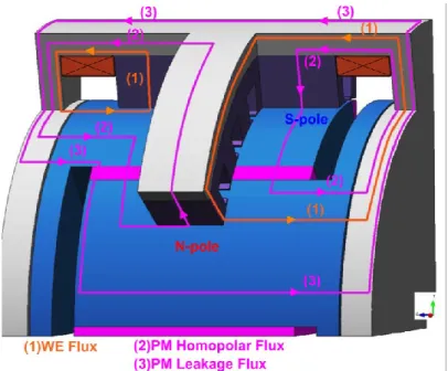
The topology selected to prove the proposed concept is a radial flux motor. The PM is located on the rotor and WE on the stator. It have been proposed by Amara et al. in 2009 [35], and studied theoretically and experimentally in [67], [68], [69]. Figure 2-8 provides a 3D view of the selected topology for HESM (modelled in MagNet Infolytica). The main flux paths for PMs and WE, as well as, the PM leakage flux are displayed in the motor. For this research work, some modifications in the magnetic and mechanical design of the rotor and outer stator are made. The left-side excitation coil regulates the S-pole flux, whereas the right-side coil is responsible for the flux regulation of the N-pole. The outer stator provides a magnetic path for WE flux. In this parallel hybridization topology, the rotor claw-pole structure prevents the flux from the N-pole to interfere into the S-pole. This design has easy flux control, high efficiency, wide CPSR, and good reliability [70]. However, it has 3D flux paths, for which the FEA analysis is very time- and process-consuming. The homopolar and leakage fluxes contribute in the hard saturation of outer stator magnetic material (see Figure 2-8). This motor will be studied and optimally designed in the following chapters.
Figure 2-8 Selected HESM topology with minor modifications: 1- PMs (ferrite), 2-rotor claws (iron–silicon alloy), 3- stator coils (copper), 4- stator (silicon steel lamination), 5-outer stator (iron–silicon alloy), 6-WE coils (copper)
HESM modelling and analysis
2.3
The commonly used tools for electromagnetic analysis include Finite Element Analysis (FEA), analytical model and winding function theory, and Magnetic Equivalent Circuit (MEC) [71], [72]. In the design optimization of HESM, the number of simulation to build the efficiency maps for different HRs is enormous. FEA approach is very accurate, but takes lots of time and resources, especially for machines with 3D flux directions. FEA can be practical for one or limited number of operating points; however, it is not applicable here. Analytical approximate formula and winding function theory lack desirable accuracy. Being analytical semi-numerical, the non-linear MEC can make a trade-off between the time and accuracy, and can be very helpful in the design optimization of HESM with 3D flux paths [73], [74], [75]. This approach provides acceptable accuracy, with fast simulation to reduce the processing burden of optimization.
MEC has long been an alternative, yet effective, method to FEA for electrical machines, with shorter computation time and accuracy of results. It has been used for the design and analysis of different types of electric machines, such as switched reluctance motors, asynchronous motors, and permanent magnet motors [76], [77], [78], [79], [80]. It has gained more attention and applicability recently in the literature [81], [82]. Several universities are working on MEC modelling and have their own developed software, which is flexible for different motor designs, materials, and analyses. In University of Grenoble Alpes, for instance, researchers in G2ELab have developed a software tool for MEC analysis, namely Reluctool [83].
46 Literature Review on Design, Modelling, Optimization, and Control of Hybrid Excitation Synchronous Machines (HESMs) for Electric Vehicles
There are two circuit laws governing the formulation of MEC, namely, Kirchhoff Current and Voltage laws [84]. The nodal-based analysis is applying the Kirchhoff Current lows and is widely appreciated due to its simplicity of implementation. The principles are the same as that of the electric circuits; only here we use the magnetic variables. There are two methods for nodal-based analysis, namely, tooth contour and flux tube. The flux tube method has been selected to be applied to the HESM. The approach in [85], [86], and [87] are the guidelines with more detailed explanation,. The final non-linear 3D MEC model of the HESM under study is developed, explained, and evaluated by FEA in [88].
HESM optimization
2.4
Having developed the HESM model using MEC technique, optimization algorithms can find the optimal design. The design optimization of HESM is simply composed of two stages: design, and optimization. The objective of design stage is to provide feasible solutions for the problem under study, and then, the optimization takes it towards the optimal point regarding the desired objective functions. The optimization algorithms used for the optimization of electric machine are divided into two main groups, i.e. gradient-based algorithms and intelligent optimization algorithms, as displayed in Figure 2-9.
Figure 2-9 Optimization algorithms used for design of electrical machines (based on [89])
Gradient-based algorithms need analytical expressions and linear MEC models for the evolution of objective functions towards the optimal point. However, today electrical machine optimization is using non-linear models, such as FEA or non-linear MEC for the motor modelling and analysis. Therefore, intelligent optimization algorithms have been employed for the optimization of electrical machines in the past several years [90]. As the nature of electrical machine optimization consists of several objective functions, multi-objective optimization has become popular in this field [19], [91], [92]. These objective functions are sometimes paradoxical, e.g. efficiency and cost, and multidisciplinary, e.g. electric, magnetic, thermal, and mechanical
objective functions. Typical structure of an optimization process is displayed in Figure 2-10, which comprises of main stages (left-hand boxes) and exemplary tasks (right-hand boxes); bold solid lines give loops for possibly required iteration(s).
Figure 2-10 Typical structure of an optimization process (based on [93]).
NSGA-II [94] is generally considered the state of the art algorithm in evolutionary multi-objective optimization, which has provided good results in the optimization of electric machines [95], [96] and [97]. Our contribution regarding the optimization of electric machines using NSGA-II is described in [98].
HESM control
2.5
The well-known principles of dq-reference control of PM machines can be fully absorbed in HESM control. PM machine control through d- and q-axis currents applies different control strategies for different regions of motor T-S plane. For instance, prior to base (rated) speed, Maximum Torque per Ampere (MTPA) strategy is applied. From base speed to maximum speed, the voltage constrain is reached, and Maximum Torque per Voltage (MTPV) control should be applied. The nonlinearities can be taken into consideration by a nonlinear inductance computation through curve fitting techniques for different current levels [99]. Combining these techniques with the PMSM and WESM loss minimization control [100], [101] provides the possibility to achieve multi-objective control strategies for HESM [102].