HAL Id: hal-01089319
https://hal.inria.fr/hal-01089319
Submitted on 1 Dec 2014
HAL is a multi-disciplinary open access
archive for the deposit and dissemination of
sci-entific research documents, whether they are
pub-lished or not. The documents may come from
teaching and research institutions in France or
abroad, or from public or private research centers.
L’archive ouverte pluridisciplinaire HAL, est
destinée au dépôt et à la diffusion de documents
scientifiques de niveau recherche, publiés ou non,
émanant des établissements d’enseignement et de
recherche français ou étrangers, des laboratoires
publics ou privés.
Design Flow and Run-Time Management for
Compressed FPGA Configurations
Christophe Huriaux, Antoine Courtay, Olivier Sentieys
To cite this version:
Christophe Huriaux, Antoine Courtay, Olivier Sentieys. Design Flow and Run-Time Management
for Compressed FPGA Configurations. DATE - Design, Automation and Test in Europe, Mar 2015,
Grenoble, France. �hal-01089319�
Design Flow and Run-Time Management for
Compressed FPGA Configurations
Christophe Huriaux and Antoine Courtay
University of Rennes 1, Inria, Lannion, France [email protected], [email protected]Olivier Sentieys
Inria, University of Rennes 1, Lannion, France [email protected]
Abstract—The aim of partially and dynamically reconfig-urable hardware is to provide an increased flexibility through the load of multiple applications on the same reconfigurable fabric at the same time. However, a configuration bit-stream loaded at runtime should be created offline for each task of the application. Moreover, modern applications use a lot of specialized hardware blocks to perform complex operations, which tends to cancel the ”single bit-stream for a single application” paradigm, as the logic content for different locations of the reconfigurable fabric may be different. In this paper we propose a design flow for generating compressed configuration bit-streams abstracted from their final position on the logic fabric. Those configurations will then be decoded and finalized in real-time and at run-time by a dedicated reconfiguration controller to be placed at a given physical location. Our experiments show that densely routed applications gain the most with a compression factor of more than 2× using the finest cluster size, but coarser coding can be implemented to achieve a compression factor up to 10×.
Keywords—FPGA; Bit-Stream compression.
I. INTRODUCTION
FPGAs can be seen as a sea of logic elements glued together by a dense routing network assuring the data links. Because of the overhead needed by fully programmable logic elements to undertake the implementation of a complex func-tion, FPGA manufacturers add heterogeneous resources in the circuit. These cells perform more efficiently specific tasks such as arithmetic calculations (multiplications, additions, etc.) signal processing or interfacing the chip with incoming and outgoing signals. Logic elements, as well as complex cells and routing network, can be electrically programmed thanks to memory cells tied to each transistor realizing a connection on the logic fabric. Although they are evenly positioned on the circuit, all of these memory cells can be seen as a single memory layer. This configuration memory is intended to receive a bit-stream, the set of each bit determining the state of every configurable element of the FPGA. This leads to increasing bitstream sizes, up to dozens of megabits.
Most bitstream compression techniques in the literature use a compression algorithm like LZSS [1] to reduce the bitstream redundancy and thus require some logic at runtime to decompress a given bitstream. Pan et al. [2] implemented such compression technique and also applied it to reduce the redundancy between multiple bitstreams. On the contrary, Stepien et al. [3] introduced a technique to optimize the logic resources organization during the placement phase in order to reduce the distribution of these resources, which reduce the number of configuration bits required for a given task.
In this paper we introduce the Virtual Bit-Stream (VBS) coding format allowing to abstract the conventional bit-stream from the underlying routing architecture and to provide fast
relocation capabilities. A Computer Aided Design (CAD) flow associated with the generation of such bit-stream format is proposed. We also define an architecture relying on a reconfiguration controller to decode and decompress at runtime these VBSs to generate FPGA configurations depending on their physical locations. The paper is organized as follows. Section II introduces our concept of VBS, discusses the novelty of the solution and presents the general architecture associated with the flow. In Section III, we describe the design flow used to generate the VBS using the VTR framework. Experimental results are presented in Section IV where we compare the size of our Virtual Bit-Stream to a raw bit-stream. Section V concludes this paper and proposes some perspectives of this work.
II. CONCEPT OFVIRTUALBIT-STREAMS
A. Architecture
The architecture that we use to evaluate our design flow is similar to the island-style architecture used by the Xilinx Virtex circuits. The logic fabric is seen as a sea of logic blocks (LBs) distributed on a grid. The interconnection network is a mesh routing network made of single length routing wires (i.e. each wire interconnects one element of the grid with one of its neighbors). We assume that the basic logic blocks of this FPGA architecture are made of 6-input Look-Up Tables (6-LUT) associated with a flip-flop. In the standard model used by the place-and-route software used in our design flow, Versatile Place and Route (VPR) [4], the inputs and outputs of the circuits are spread on the sides of the logic fabric. However, for our experiments and in the context of dynamic reconfiguration, we will consider these inputs and outputs as part of the heterogeneous logic fabric itself.
The mesh routing network can be split into multiple elements repeated over the reconfigurable fabric to form the interconnection network. As shown in Figure 1.a, horizontal (ChanX) and vertical (ChanY) routing channels (in green) make the connection between the LBs and the routing network. A switch box (in red) is placed at the intersection of ChanX and ChanY to complete the mesh routing network.
B. Virtualization
The goal of our design flow is to produce virtualized bit-streams, which are abstracted of their final placement on the logic fabric. The process of virtualization consist in removing the inner details of the hardware task routing and to only describe its interconnection at a higher level. The virtualization process can be operated at various levels of granularity. At the finest granularity we only consider one logic element of the logic grid and its surrounding routing, consisting of the
Fig. 1: (a) Detailed view of a macro (b) Routing in a macro horizontal (ChanX) and vertical (ChanY) connection boxes ad-jacent to the logic element and one switch box interconnecting both connection boxes. These four elements together form a
macro, the simplest building block of our logic fabric which can be replicated in both the horizontal and vertical axis to build a variably sized reconfigurable fabric.
If we consider the macro depicted in Figure 1.a, the routing channels consist of W tracks connected to L inputs or outputs of the surrounding logic blocks. The switch box of the macro also connects the ChanX and ChanY together. The programmable switches of this macro are either made of pass transistors, tri-state buffers, or a combination of both. A 4-way (cross-shaped) interconnection switch will be implemented with up to six of these programmable switches, while a 3-way (T-shaped) switch will need three programmable switches. In addition to the configuration of the routing structure, the data stored into the logic elements (e.g. the LUT content or the configuration of a hardware block) also adds up to the count of required programmable bits in the configuration bit-stream.
The number of programmable switches is defined by Nraw= NLB+ 6 × [NS+ NC+] + 3 × NCT, (1)
where NLB is the size of the configuration of the logic block,
NS is the number of configurable switches in the switch
box, NC+ is the number of 4-way (cross-shaped) configurable
switches per channel, and NCT is the number of 3-way
(T-shaped) configurable switches per channel. For our architecture consisting of only 6-LUT logic blocks with a flip-flop (i.e. a logic block with 7 inputs/outputs), NLB = 26+ 1 = 65,
NC+ = 7 × (W − 1) = 28 and NCT = 7. All these
programmable switches add up to Nraw = 284 in total
for a single macro with five routing tracks. Each of these programmable switches will need one bit of configuration in the bit-stream of this hardware task. Our approach relies on the fact that the routing density varies among the surface of the reconfigurable fabric used by a considered task. The number of configuration elements in the bit-stream remains the same, although their state is set accordingly to the task to perform. The virtualization operation aims to represent the routing part of the macro in another format, smaller than the Nraw= 284
bits required to describe the full bit-stream.
In the example given in Figure 1.b, a macro with W = 5 tracks contains four routes. The routing network of this macro can be abstracted into a black box where each input and output of the black box is a connection to the surrounding routing channels or logic blocks. Each of these inputs and outputs is assigned an input/output (I/O) number which uniquely represents the I/O across the macro. The VBS corresponding to this macro contains only a list of the connections coded
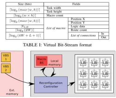
Size (bits) Fields ⌈log2(max (w, h))⌉ Task widthTask height
⌈log2(w × h)⌉ Macro count ⌈log2(max (w, h))⌉
List of macros
Position X Position Y NLB Logic data
⌈log2(2W )⌉ Route count
⌈log2(4W + L + 1)⌉ List of connections In
Out
TABLE I: Virtual Bit-Stream format
Fig. 2: Overview of a typical Virtual Bit-Stream architecture on M = ⌈log2(4 ∗ W + Nlogic IO)⌉ bits. In our example
architecture of Figure 1, M is equal to 5, which means that we can code up to ⌊Nraw
2M ⌋ = 28 connections until we reach
the point where the compression is not beneficial anymore. The final VBS is made of a header containing the hardware task metadata (e.g. its size, the number of macro) and of the list of macros coded using the aforementioned techniques. Table I describes the VBS binary format and the metadata associated with it. w and h denotes respectively the width and height of the hardware task. L is the number of inputs and outputs associated with the logic block of a given macro.
C. Runtime controller
At runtime, the VBS requires an additional decoding step in order to generate a raw configuration bit-stream compatible with the target reconfigurable fabric, as shown on the overview of the architecture in Figure 2. This figure features an external memory containing the VBSs corresponding to each task being loaded and de-virtualized by the reconfiguration controller prior to their insertion on the logic fabric. In order to keep the online decoding step as easy as possible, most of the complexity is off-loaded on the coding part of our design flow, performed offline. As such, the offline part of the flow makes sure that the generated Virtual Bit-Stream will be able to be decoded during the online part, by running the same algorithm and re-ordering the connection lists if necessary.
The de-virtualization algorithm implements a simple router. The VBS data is processed macro by macro and the con-nection list is expanded in a in-memory macro configuration representing the part of the final bit-stream corresponding to this element of the reconfigurable fabric. Since it is operating at the level of a single macro, the de-virtualization process can be easily parallelized to process multiple macro at once and thus to accelerate the decoding of a VBS. This runtime controller could be implemented and adapted to any reconfig-urable fabric. However, the absence of specifications of the bit-stream format for commercially available FPGA architectures prohibits its use on widely used reconfigurable circuits. For the purpose of our experiments, the whole Computer Aided Design
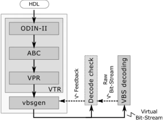
Fig. 3: CAD flow of the Virtual Bit-Stream
(CAD) flow was developed in the context of the architecture described in Section II-A.
III. CAD IMPLEMENTATION
A. VTR Tool-Flow
The design flow associated with the generation of VBS, de-picted in Figure 3, relies on the Verilog-To-Routing (VTR) [5] tool flow. This synthesis framework implements most of the required parts of our CAD flow from the hardware description synthesis to the generation of placement and routing data using the Versatile Place and Route (VPR) [4] software.
Our design flow accepts a hardware description as an input and generates a VBS according to several architecture-dependent parameters (e.g. the channel width, the LUT size) used offline. Although VTR was originally designed for aca-demic purposes as a open-source synthesis framework for the community, some recent initiatives, such as RapidSmith [6], were proposed to connect VTR to commercial Xilinx FPGA. We presently use VTR to generate a partial implementation of the considered FPGA circuit. The result is a synthesized, placed, and routed hardware task fed into our custom VBS generation backend. The VTR part of our design flow could be replaced by any other framework generating similar data.
B. VBS Generation Backend
In contrast to the raw upstream data generated by VTR, our VBS generation software vbsgen outputs a usable VBS ready to be loaded onto the target platform. Vbsgen uses the placement, routing and netlist data obtained from VPR in con-junction with a detailed software model of the reconfigurable architecture to generate the final VBS. The architecture model overlaps with the one used by the VTR framework as it de-scribes the composition of the logic grid of the reconfigurable fabric as well as the structure of the interconnection network of the circuit. Additional data is included in the vbsgen model for the bit-stream generation operation: detailed information on the routing structure and methods to serialize the logic block data are required in addition to what is already present in the VTR architecture.
Internally, vbsgen builds a complete usable description of the target reconfigurable architecture in memory using its model and parameters passed at runtime (e.g. number of tracks in a channel, size of the LUTs). This internal model needs to be thoroughly defined since every slight difference between the VTR architecture, the vbsgen architecture model, and the
Name Size MCW LBs alu4 35 9 1173 apex2 39 12 1478 apex4 32 15 970 bigkey 27 8 683 clma 79 15 6226 des 32 8 554 diffeq 30 10 869 dsip 27 9 680 elliptic 47 13 2134 ex1010 56 16 3093 Name Size MCW LBs ex5p 28 13 740 frisc 55 16 2940 misex3 35 11 1158 pdc 61 15 3629 s298 37 8 1301 s38417 58 8 3333 s38584.1 65 9 4219 seq 37 12 1325 spla 55 14 3005 tseng 29 8 799
TABLE II: Benchmark set used (MCW: Minimum Channel Width) (LB: Logic Block)
target architecture can lead to the generation of invalid bit-streams. As stated in Section II-C, vbsgen is responsible for the generation of valid bit-streams that the online controller will be able to decode at runtime. To enforce this behavior and ensure that the online decoding will meet the requirements, the de-virtualization algorithm used online is implemented in software and included in a feedback loop during the offline generation of the VBS. Because of the stateful nature of the decoding algorithm, the order of the connections in the connection list of each macro has an important impact on the success of finding a valid routing online. As such, if a generated VBS is proven non-routable by the feedback loop, the connections are re-ordered to find a non ambiguous order. In the end, if no feasible connection list is found, the raw coding of the considered macro is included in the VBS instead of the smart connection list. This fallback behavior can induce lesser compression gains but guarantees that the hardware task will be handled correctly in all cases during the online placement.
IV. EXPERIMENTALRESULTS
In this section we evaluate the effects of the VBS described in Section II, using the general architecture introduced in Sec-tion II-A. The logic blocks contain a 6-input LUT associated to a flip flop. We used a set of the 20 largest benchmarks from the MCNC circuit suite [7] to test our design flow, listed in Table II. Of these 20 benchmarks, 13 of them contain over a thousand logic blocks. These benchmarks where packed into 6-LUT logic blocks and synthesized using VPR. We let VPR perform its routing using the minimum channel width guaranteeing a feasible routing, as indicated in the MCW column of Table II. In order to make a comparable analysis of these benchmarks together, we normalized these circuits with a channel width of 20 tracks during the generation of the raw bit-streams and the Virtual Bit-Streams. The following subsection studies the compression induced by the Virtual Bit-Stream coding. In subsection IV-B, we analyze the effect of the the VBS at a coarser grain.
A. Bit-Stream Compression
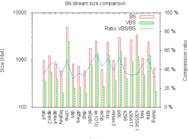
As stated in previous sections, the abstract coding of the VBS allows to reduce the storage space footprint of a considered hardware task in comparison to a raw bit-stream. Figure 4 depicts the results of the coding of the 20 MCNC benchmarks into a raw bit-stream (BS) and a Virtual Bit-Stream (VBS). A logarithmic scale is used on the size axis because of the high variance in term of logic area of the benchmark circuits.
We observe an average compression ratio of 41% of the raw bit-stream size over the 20 circuits using our VBS coding.
Fig. 4: Comparison of the size of raw bit-streams and Virtual Bit-Streams
Fig. 5: Effect of the macro cluster size on the VBS size The VBS coding is especially efficient in sparse macro of the circuits where the routing network is not fully used, whereas congested locations see little to no enhancement over the bit-stream size. Overall, the VBS performs constantly better in terms of size in comparison to the raw coding. In the eventuality where the VBS coding would be bigger than the raw one, it would be possible to simply use the raw coding of the most congested macro of the circuit in order to still be at least as good as the original bit-stream.
B. Virtual Bit-Stream Clustering
The examples introducing the VBS in Section II assumed the finest possible grain of coding in the context of our work: one logic block, surrounded by its local routing. It is also possible to use a coarser grain for the routing abstraction, by clustering multiple macros together. This aggregation allows to pool the routing resources of the cluster and thus to provide a higher level of abstraction, at the cost of increased computing needs at runtime to perform the online de-virtualization of the VBS.
Figure 5 depicts the results of the bit-stream creation of the 20 MCNC benchmarks on the same architecture used for the compression comparison. The cluster size is expressed in terms of number of macros per square side of the cluster, as
we only consider regular square clusters. A cluster of size 2 thus aggregates 4 macros together. For each cluster size, the minimum and maximum values of the VBS size of the 20 benchmarks is given by the error bars, along with the geometric mean of this size across the benchmark suite. An additional indicator presents the average value of the compression ratio as a percent of the original raw bit-stream size. As shown by Figure 5, the clustering has a important effect on the compression ratio which decreases from 41% to 9%-15% of the original raw bit-stream size for superior cluster sizes. It shall be noted that although going from no clustering at all to clusters of size 2 increases the compression by a factor of 4×, higher sizes of clusters shows less benefits and can be even worse in terms of bit-stream size, while needing higher computing power to decode.
V. CONCLUSIONS AND FUTURE WORK
This paper presents a design flow for generating com-pressed configuration bit-streams abstracted from the lower-level routing details of the reconfigurable architecture and from their final position on the reconfigurable fabric. The VTR framework has been expanded to include bit-stream generation features. A bit-stream format is proposed to take part of our approach and the associated architecture was presented. We analyzed the compression induced by our coding method and proved that compression ratios of at least2.5× can be achieved on the 20 largest MCNC benchmarks. The introduction of clustering which aggregates multiple routing resources together showed compression ratio up to a factor of10×, at the cost of a more complex decoding step at runtime. Future perspectives on the VBS include extension of the architecture to support commercially available FPGAs as well as the improvement of the associated CAD tool flow to include smarter coding of the VBS to gain in runtime efficiency and in size. The VBS approach can provide increased online relocation capabilities thanks to a decoding algorithm capable of decoding the VBS on-the-fly during the task migration.
ACKNOWLEDGMENT
This research is sponsored by the European Commission under the 7th Framework program within the FlexTiles project (FPT ICT-288248) and by the French Ministry of Research.
REFERENCES
[1] Z. Li and S. Hauck, “Configuration compression for Virtex FPGAs,” in
the Symp. on Field-Programmable Custom Computing Machines. IEEE, 2001, pp. 147–159.
[2] J. H. Pan, T. Mitra, and W.-F. Wong, “Configuration bitstream compres-sion for dynamically reconfigurable fpgas,” in the Int. Conf. on Computer
Aided Design. IEEE, 2004, pp. 766–773.
[3] P. Stepien and M. Vasilko, “On feasibility of FPGA bitstream com-pression during placement and routing,” in the Int. Conf. on Field
Programmable Logic and Applications. IEEE, 2006, pp. 1–4. [4] V. Betz and J. Rose, “VPR: A new packing, placement and routing tool
for FPGA research,” in the Int. Conf. on Field Programmable Logic and
Applications. Springer, 1997, pp. 213–222.
[5] J. Rose et al., “The VTR project: architecture and CAD for FPGAs from verilog to routing,” in the Int. Symp. on Field Programmable Gate
Arrays. ACM, 2012, pp. 77–86.
[6] E. Hung, F. Eslami, and S. J. Wilton, “Escaping the academic sandbox: Realizing VPR circuits on Xilinx devices,” in Int. Symp. on
Field-Programmable Custom Computing Machines. IEEE, 2013, pp. 45–52. [7] S. Yang, Logic synthesis and optimization benchmarks user guide: