A PLATFORM FOR THE FAST INTERPRETATION OF MOVEMENTS
AND LOCALIZATION OF USERS IN 3D APPLICATIONS DRIVEN BY A
RANGE CAMERA
Sébastien Piérard , Vincent Pierlot, Olivier Barnich, Marc Van Droogenbroeck, Jacques Verly
INTELSIG Laboratory, Montefiore Institute, University of Liège, Liège, Belgium
ABSTRACT
Interactivity is one of the key challenges for immersive applica-tions like gaming. Manufacturers have been working towards in-terfaces that are driven by a device (e.g. a Wiimote) or inin-terfaces that are controlled by a camera with a subsequent computer vision module. Both approaches have unique advantages, but they do not permit to localize users in the scene with an appropriate accuracy. Therefore, we propose to use both a range camera and accurate range sensors to enable the interpretation of movements.
This paper describes a platform that uses a range camera to acquire the silhouettes of users, regardless of illumination, and to improve the pose recovery with range information after some image processing steps. In addition, to circumvent the difficult process of calibration required to map range values to physical distances, we complete the system with several range laser sen-sors. These sensors are located in a horizontal plane, and measure distances up to a few centimeters. We combine all these mea-surements to obtain a localization map, used to locate users in the scene at a negligible computational cost. Our method fills a gap in 3D applications that requires absolute positions.
Index Terms — Detectors, distance measurement, image
anal-ysis, image shape analanal-ysis, interactive computing.
1. INTRODUCTION
The gaming industry is working towards immersive systems that offer both impressive performances and an intuitive interface. Mi-crosoft, with its announcement of a new interface (built around a range camera) for its Xbox, has raised the next generation inter-faces to an even higher standard.
Whereas motion capture is intended to achieve a perfect re-construction of a user’s movements, often at the price of a loss of responsiveness and discomfort (a user has to carry tags), gaming does not require such a degree of motion fidelity. In this paper, we consider the scope of an interactive application driven by a range camera (also called 3D, distance, or depth camera) and other range devices, where unobtrusiveness is mandatory. Consequently, so-lutions that require one to hold a controller (such as the Wiimote of Nintendo), to wear (passive or active) tags for motion capture or for localization are discarded.
Depth maps, as provided by range cameras, ease the interpre-tation of movements made by users. In theory, it is possible to localize users from depth maps, but at the cost of an additional computer vision module. But practice shows that mapping range data to precise and accurate distances remains a difficult problem. Note that the absolute positioning of users is also an issue in
mo-Figure 1. Two range sensors: a PMD camera (PMD[vision]19k) on the left hand side, and a rotating laser sensor (BEA LZR P-200) on the right hand side.
tion capture, where one often sees users drift (or slide) while walk-ing.
We have designed a platform that combines a range camera and range laser sensors (also called rotating laser sensors). While the range camera helps to interpret the user’s movements, the range laser devices are useful to localize users in the scene since they of-fer both a better precision and a better accuracy.
The remainder of this paper is organized as follows. Section 2 describes the two kinds of range sensors used in our platform (see Figure 1). Sections 3 and 4 respectively detail how it is possible to interpret the behavior of users and to localize them in the scene. For the localization, we develop the notion of a localization map that tracks the position of users in an horizontal plane. Section 5 concludes this paper.
2. RANGE SENSORS
The usual setup for a camera based interface is that of a camera lo-cated in front of the users. The constraint of placing the camera in front of the scene is not the only one. Color cameras require a con-trolled, if not constant, illumination, and have severe limitations (objects in the foreground and background sharing the same col-ors are indistinguishable, distances are derived from colcol-ors instead of measuring the distance, etc). Therefore, applications often rely on an additional 3D model to interpret the scene and movements. But the reasonable question to ask is whether or not 3D models are better matched to the information provided by a range camera. Among the advantages of range sensors, let us emphasize three of them:
1. Range is a valuable information for interactive 3D appli-cations (like gaming), which limits the computational cost. By contrast with 2D cameras that have to estimate 3D co-ordinates, the behavior analysis is derived from a simpler computer vision module, which makes the range informa-tion suitable for real-time and low cost applicainforma-tions. Note
(a) (b)
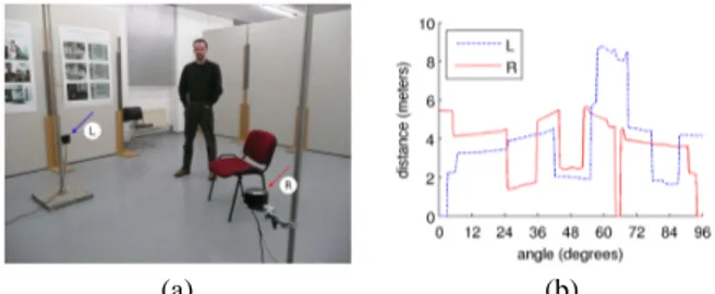
Figure 2. Two laser sensors and their distance measurements on a graph. (a) Two arrows (blue and red) point to the laser sensors at the left (L) and right (R) sides of the scene. (b) The respective signals.
that stereoscopic vision is an alternative way to retrieve range information but, in an uncontrolled scene, the po-tential lack of texture or contour information could cause the stereoscopic vision to fail;
2. Range sensors operate with their own light sources and are thus independent of lightning conditions. These devices are usable in dark rooms, like projection rooms, or in a room where illumination changes are common, such as changes caused by light through a window;
3. Finally, range sensors are unobtrusive. They do not require the users to wear active or passive tags.
Next, we describe the technology of the two components of our platform: range cameras and rotating laser scanners.
2.1. PMD cameras
PMD (Photonic Mixer Device) cameras are a widespread tech-nology for range cameras. The principle is as follows. A light source emits an infrared signal modulated in amplitude. The cam-era receives a time-delayed and attenuated return signal, plus some ambient light. The emitted and received signals are compared to estimate distances (which are proportional to the phase shift). The derivation of a simple theoretical model and a discussion of the numerous imperfections can be found in [1, 2, 3, 4]. For exam-ple, it is shown that precision is obtained at the price of a longer integration time. Radmer et al. [5] have reported errors on the dis-tance measurements of up to 0.3m. The difficulties to calibrate
the camera have also been raised in several papers.
Despite their inaccuracy, range cameras are usable to under-stand the behavior of users (see Section 3). We use a PMD camera
PMD[vision] 19k (see Figure 1). It produces images at low
reso-lution (160 × 120 pixels) and at low frame-rate (about 5.7fps).
2.2. Rotating laser sensors
Laser range sensors are also a known technology. Simple devices measure distances for a few 3D directions, but more sophisticated sensors exist. For example, there are devices that are used in con-junction with rotating mirrors to scan a 360° field of view.
Our platform uses rotating laser sensors BEA LZR P-200 (see Figure 1) for the localization. Each sensor scans four planes and spans an angle of 96°; in our work, a single plane suffices. In a plane, 274 distance measures are taken at a frequency of 15 times per second. We observe that measurement errors are at most of
0
.03m. Figure 2 shows the positioning of two laser sensors and
their respective raw data. One strength of using these sensors is that their raw data are expressed in meters directly, and that no
calibration is needed due to their good accuracy. However, the in-terpretation of the raw data is not straightforward. This motivates us to build a localization map instead of using the raw data (see Section 4). We have designed a real-time algorithm that trans-forms the angular measurements in an euclidean plane, and that intersects the results provided by an arbitrary number of sensors.
3. A RANGE CAMERA TO UNDERSTAND THE BEHAVIOR
For interactivity, analyzing the behavior of users is essential. Tex-ture, contours, or distances are all valid pieces of information for understanding the scene. But, as stated in [6], silhouettes «clearly encode a great deal of useful information about 3D pose». Here-after, we explain how range cameras can be used to acquire the silhouettes of the users, and how to improve pose recovery with depth. In the next Section, we explain how to localize users.
3.1. First step: silhouette extraction
Background subtraction algorithms separate pixels where no mo-tion is detected (background) from pixels of moving objects (fore-ground). Those objects correspond either to the users or to the physical objects users interact with. The result of background sub-traction algorithms is a binary map. A connected component anal-ysis of this map separates the silhouettes of the different users. As shown in [1], background subtraction techniques are useful not only for color cameras, but also for range cameras. The exis-tence of several reliable background subtraction algorithms, such as ViBe [7], makes it tractable to detect silhouettes in real time. To some extent, it makes more sense to use a background subtraction terminology for range sensors than for color cameras, since color cameras do not measure distances.
Although it is both fast and efficient to extract silhouettes from range data with a background subtraction algorithm, some ambi-guities are proper to devices like range cameras. For example, since feet are very close to the ground, the correct segmentation of the feet remains problematic. If such problems are to be solved, one could combine range data to color data (see [1] for a techni-cal description). However, color cameras introduce some require-ments on the lightning conditions.
3.2. Second step: improving the pose recovery with a depth annotation
As stated in [6], the information about poses provided by silhou-ettes is essential. The only problem is that distinct poses can lead to identical silhouettes. Here, we can see the advantage of using a range camera: range cameras are not only efficient in extracting silhouettes, but they can also be used to improve the pose recovery by providing valuable range information to overcome the under-determination of poses. For this purpose, we annotate silhouettes with information derived from the range map. Figure 3 illustrates the principle of our method, which consists in a normalization of the values of the depth map for each connected component inde-pendently.
Since the annotation should only reflect the pose, we need nei-ther a precise distance measure, nor a precise localization; we only have to take care of noise on the data and filter it out if necessary. Consequently, we normalize the range data inside each connected component to fit the range data into an interval form 0 to 1. Fig-ure 4 shows some results in a real 3D interactive application.
(a) (b) (c) (d) (e) (f)
Figure 3. Illustration of our mechanism to overcome the pose under-determination. (a, b) A virtual human with two different poses (the right arm in front of, and behind, the torso). (b, c) The silhouettes of (a) and (b) are similar. (e, f) But, the range annotations of the two silhouettes are different, which helps to differentiate poses.
(a1) (b1) (c1)
(a2) (b2) (c2)
Figure 4. Results of the normalized depth annotation procedure. (a1, a2) Two depth maps acquired with a range camera. Poses are hardly distin-guishable on the range images. (b1, b2) are the silhouettes resulting from a background subtraction algorithm applied to the stream of the range camera. (c1, c2) The silhouettes annotated with a normalized depth map (darker values stand for closer distances).
4. USING LASER SENSORS TO LOCALIZE USERS
It is easy to detect the location of users in the image plane. But it is much harder to locate them in the real 3D world. Therefore, most solutions, including motion capture solutions, only derive a relative position between the camera and users. The applications then know if users are moving forward or backward, but ignore the precise location of users.
3D localization can be achieved in multiple ways; details about indoor localization systems can be found in [8]. In our application we did not consider systems like the Active Badge [9] or RFIDs, since we wanted to design an unobtrusive interface.
As our interface comprises a range camera, we did first try to derive 3D locations from the raw data. Unfortunately, using a PMD camera to locate people is difficult for three reasons: (1) the device should be calibrated, but this calibration is difficult [1], (2) depth maps are neither an accurate nor a precise distance estima-tion; increasing the integration time does not solve all the issues, (3) last but not least, the bias on the measurements is related to the physical properties of observed objects [3, 5], which are unknown in most applications. Consequently, in arbitrary scenes, localiza-tion is not straightforward with PMD cameras. We had to look for an alternative.
4.1. Using rotating lasers to localize users
In contrast to PMD cameras, laser rotating sensors are accurate and precise, and do not require any calibration. Thus, to local-ize users, we use rotating lasers placed in such a way that all the measurements are taken in a common horizontal plane.
Measur-(a) (b)
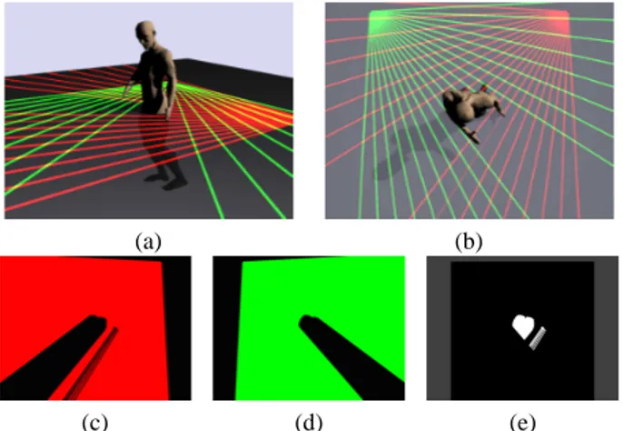
(c) (d) (e)
Figure 5. Illustration of the localization procedure with two rotating laser sensors. (a) A virtual scene with a person and two sensors. Only a small number of laser beams are shown per sensor. (b) The same scene seen from the ceiling. (c, d) Areas in line-of-sight of each sensor. (e) The reconstructed slice of the scene (called localization map), obtained as the union of areas visible to at least one sensor. Note the presence of shadows in the final localization map.
ing distances in a common zone with several sensors is possible as, for pulse based laser scanners, the risk of interference between sensors is negligible. On the contrary, several PMD cameras send the same modulated signals over the scene and, therefore, cannot be used simultaneously.
As shown in Figure 2, the interpretation of the angular raw data is not straightforward. To ease the localization of users, we have developed a new algorithm (not described in this paper) that serves two purposes: project the angular data in a 2D euclidean plane, and merge data from an arbitrary number of sensors. The result, called localization map, is a 2D binary map that indicates where objects are believed to be located horizontally at the height of the sensors. Figure 5 illustrates the procedure.
The mapping from angular data to the euclidean space pro-duces shadows. Shadows appear in zones that are not in line-of-sight of a laser. It is possible to reduce shadowed zones by combining measures from several sensors. Indeed, a point that is visible from a sensor frees the path for all points located on the straight line between them. Our algorithm is fast enough to ac-cept many laser sensors in real time, so that one could place more sensors to overcome shadowing effects if needed.
When several sensors are used, a registration of the individual localization maps is required to combine the maps. In practice, this registration is easy to do since there are only three degrees of freedom per sensor: its 2D position, and its orientation in the common scanning plane. Once the coordinates of the sensor in the plane are known, we calibrate the system by adjusting its orienta-tion manually and visually thanks to its localizaorienta-tion map. We did not had to develop an additional calibration tool.
4.2. Shortcomings of the localization maps and solutions
As explained above, shape deformations (caused by shadows) can be observed on the localization map. A solution is to use sev-eral sensors. Fortunately, our application does not require a per-fect localization map, and good results are obtained with only two sensors. It is up to the user to optimize the positions of lasers to reduce shadows to a minimum.
(a) (b)
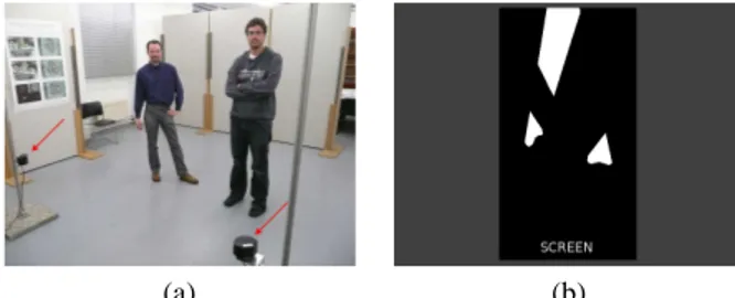
Figure 6. Result of the localization procedure in a real 3D interactive application. Users are looking towards a screen. The aim is to focus on the user which is the closest to the screen, and to localize him. Two rotating laser sensors are located on the left and on the right of the screen, and not in front of the user. (a) The scene seen from the screen wall. Red arrows point to the laser sensors used to build the localization map. (b) The localization map. An important ghost appears at the top of the map. Since the ghosts always appear behind the users, their presence has no negative impact in our application.
ghosts (as seen on Figure 6). Ghosts are connected components that could be objects with unrealistic shapes but are more prob-ably only an artifact introduced by shadows. They appear when there are several users or objects in the scene. If adding sensors is impossible, a connected component analysis could help to handle the ghosts: ghosts are always invisible to all sensors due to the presence of other connected components.
The localization map is also influenced by the presence of un-interesting static objects (chairs, tables, . . . ) in the scene. In a dynamic interpretation of the scene, one could filter out static ob-jects from the localization map by using a background subtraction algorithm.
Finally, it should be noted that the height of the plane covered by the laser beams has to be chosen with appropriate care. If the sensors are located at a height of one meter from the floor, arms are visible on the map. If the plane is moved downwards, then small objects (chairs, pets, tables, . . . ) could appear in the map.
4.3. Applications of the localization maps
Localization maps are useful for many applications (localization of users, robotic navigation, obstacle avoidance, etc) and they fill a real gap in the design of interfaces. One advantage of our lo-calization procedure is that of flexibility. Sensors can be placed anywhere (at the corners, in the front, at the back, etc), and a lo-calization map can be obtained with any number of sensors.
The major problem that the map solves is the localization of users. In some applications, there is even no need for advanced processing such as the suppression of static elements and ghosts. For example, we were asked to implement a robust localization of the user closest to the screen in a projection room. Given the localization map and the knowledge of the screen location, we only had to look for the closest blob in the localization map, and could just ignore all the problems introduced by shadows. All the processing can be done at negligible computational cost.
5. CONCLUSIONS
The use of range sensors has recently received a significant in-crease of interest due to the existence of products available at a reasonable price. Some manufacturers believe that range sensors will play an important role in advanced 3D applications (in the field of immersive gaming, the movie industry, etc). A major
ad-vantage is that applications can be totally independent of lightning conditions, and even work in total darkness, such as encountered in projection rooms.
In this paper, we describe a platform to process 3D informa-tion in real-time. Two innovainforma-tions are proposed: (1) an improved data processing to be used for pose recovery and behavior under-standing, and (2) a new localization technique. The localization technique transforms and summarizes angular data from an arbi-trary number of sensors to provide a map that shows all zones visible to a least one sensor. This map is the key to localize users, but it could be useful for any application that needs accurate and absolute locations.
Acknowledgments
This work was partially supported by the Belgian Walloon Region, under the AURALIAS (WIST 2) project. S. Piérard has a grant funded by the FRIA, Belgium. We are also grateful to BEA for their help.
6. REFERENCES
[1] J. Leens, S. Piérard, O. Barnich, M. Van Droogenbroeck, and J.-M. Wagner, “Combining color, depth, and motion for video segmentation,” in Computer Vision Systems. 2009, vol. 5815 of Lecture Notes in Computer Science, pp. 104–113, Springer. [2] S. Piérard, J. Leens, and M. Van Droogenbroeck, “Real-time processing of depth and color video streams to improve the re-liability of depth maps,” in Proceedings of 3D Stereo MEDIA, Liège, Belgium, November 2009.
[3] M. Lindner and A. Kolb, “Calibration of the intensity-related distance error of the PMD TOF-camera,” in SPIE: Intelligent
Robots and Computer Vision XXV, 2007, vol. 6764, pp. 6764–
35.
[4] D. Silvestre, “Video surveillance using a time-of-flight cam-era,” M.S. thesis, Informatics and Mathematical Modelling, Technical University of Denmark, DTU, 2007.
[5] J. Radmer, P. Fusté, H. Schmidt, and J. Krüger, “Incident light related distance error study and calibration of the PMD-range imaging camera,” in IEEE International Conference
on Computer Vision and Pattern Recognition (CVPR),
Piscat-away, NJ, 2008, pp. 23–28.
[6] A. Agarwal and B. Triggs, “3D human pose from silhouettes by relevance vector regression,” in IEEE International
Con-ference on Computer Vision and Pattern Recognition (CVPR),
2004, vol. 2, pp. 882–888.
[7] O. Barnich and M. Van Droogenbroeck, “ViBe: a power-ful random technique to estimate the background in video se-quences,” in International Conference on Acoustics, Speech,
and Signal Processing (ICASSP 2009), April 2009, pp. 945–
948.
[8] Y. Gu, A. Lo, and I. Niemegeers, “A survey of indoor posi-tioning systems for wireless personal networks,” IEEE
Com-munications Surveys & Tutorials, vol. 11, no. 1, pp. 13–32,
2009.
[9] R. Want, A. Hopper, V. Falcao, and J. Gibbons, “The active badge location system,” ACM Transactions on Information
![Figure 1. Two range sensors: a PMD camera (PMD[vision]19k) on the left hand side, and a rotating laser sensor (BEA LZR P-200) on the right hand side.](https://thumb-eu.123doks.com/thumbv2/123doknet/6839229.190810/1.918.474.801.343.432/figure-range-sensors-camera-vision-rotating-laser-sensor.webp)