STALL MARGIN PREDICTION AND IMPROVEMENT FOR MIXED FLOW COMPRESSORS
NOUREDDINE DJEGHRI
DÉPARTEMENT DE GÉNIE MÉCANIQUE ÉCOLE POLYTECHNIQUE DE MONTRÉAL
THÈSE PRÉSENTÉE EN VUE DE L’OBTENTION DU DIPLÔME DE PHILOSOPHIAE DOCTOR
(GÉNIE MÉCANIQUE) AOÛT 2016
ÉCOLE POLYTECHNIQUE DE MONTRÉAL
Cette thèse intitulée :
STALL MARGIN PREDICTION AND IMPROVEMENT FOR MIXED FLOW COMPRESSORS
présentée par : DJEGHRI Noureddine
en vue de l’obtention du diplôme de : Philosophiae Doctor a été dûment acceptée par le jury d’examen constitué de :
M. REGGIO Marcelo, Ph. D., président
M. VO Huu Duc, Ph. D., membre et directeur de recherche M. GUIBAULT François, Ph. D., membre
ACKNOWLEDGEMENTS
First of all, I would like to express my deep gratitude to my advisor Huu Duc Vo, who gave me the chance to work with him on this very exciting but complex topic about rotating stall inception and its control. Without his guidance, support, and help, this project would not be possible. I am also grateful to our industrial sponsor for their financial support.
I also thank Calcul Canada for allowing me to run most of the unsteady simulations, presented in this thesis, on their cluster computer Cottos as well as the assistance received from Calcul Québec’ team on many occasions when it was needed.
I would also, like to express my appreciation for my thesis committee, consisting of Dr. Marcelo Reggio, Dr. Francois Guibault, Dr. Wahid Ghaly, and Dr. Richard Gourdeau, for the time they have devoted to reading and evaluating my thesis.
Finally, the unconditional, financial and moral, support of my parents is without doubt the main impetus for advancing in my studies.
RÉSUMÉ
Les instabilités aérodynamiques dans les compresseurs sous la forme du décrochage tournant (rotating stall) et du pompage (surge) sont des phénomènes connus qui limitent l’enveloppe d’opération des turbines à gaz. Le décrochage tournant est caractérisé par la formation d’une cellule d’écoulement de vitesse déficiente qui tourne à une fraction de celle du compresseur alors que le pompage est une oscillation axisymétrique de l’écoulement à travers la turbine à gaz. Ce dernier mène à une chute soudaine de la puissance du moteur et entraîne souvent des dommages au moteur. Une marge de sécurité doit être mise entre le point d’opération et le point de pompage à la même vitesse de rotation, et est connue sous le nom de ‘surge margin’. Comme le décrochage tournant dans le compresseur est souvent à l’origine du pompage dans le moteur, le surge margin est l’équivalent du ‘stall margin’ (ou marge au décrochage tournant) lorsqu’on considère le compresseur tout seul. Vu son importance, on a besoin de pouvoir prédire le point de décrochage (tournant) durant la phase de conception du compresseur afin de pouvoir déterminer avec précision le stall margin. Il est aussi nécessaire de développer des stratégies efficaces pour retarder le point de décrochage afin d’augmenter un stall margin insuffisant sans pénaliser la performance du compresseur au point de design. Au niveau de la prédiction du décrochage tournant, la recherche récente a proposé des critères prometteurs liés à l’écoulement de jeu d’aube pour prédire pour des compresseurs axiaux le décrochage tournant de type pip initié par des perturbations à courte longueur d’onde, qui est le type le plus commun dans les compresseurs modernes. Les traitements de carter, sous la forme de fentes dans le carter au-dessus des rotors, ont été étudiés depuis plusieurs décennies comme une technologie de suppression passive du décrochage tournant. Cependant, leurs conceptions ont été empiriques et augmentent souvent le stall margin au dépend du rendement optimal du compresseur. Bien que certain travaux récents ont indiqué la possibilité d’obtenir des traitements de carter par fentes axiales qui peuvent prévenir la perte du rendement optimal dans les compresseurs axiaux, il n’existe aucune règle de conception systématique pour permettre d’optimiser l’augmentation du stall margin tout en prévenant la perte du rendement optimal. De plus, la grande majorité de la recherche sur ces deux aspects a été faite pour le compresseur axial, qui est le type le plus utilisé dans les moteurs d’avion. Toutefois, presqu’aucun travail n’a été fait sur le compresseur à écoulement mixte qui commence à retrouver son chemin dans les nouveaux petits moteurs d’avion. Ce type de
compresseur est un hybride entre le compresseur axial et le compresseur centrifuge et donne une augmentation de pression par étage plus importante que celui des compresseurs axiaux.
Les objectifs de la présente recherche consistent à déterminer des critères pour prédire le décrochage tournant de type pip dans les compresseurs à écoulement mixte et d’établir des règles de conception préliminaires pour produire un traitement de carter qui augmenterait significativement le stall margin sans pénaliser le rendement optimal pour ce type de compresseurs. Les résultats de cette recherche aideront le processus de conception des compresseurs à écoulement mixte. Une approche numérique sur un rotor de compresseur à écoulement mixte de moteur d’avion a été choisie pour rencontrer les objectifs. Pour le premier objectif, des simulations numériques de l’écoulement (CFD) ont été faites jusqu’à la limite de convergence de la caractéristique du rotor. Selon le montage numérique, ce point représenterait le point de décrochage tournant de type pip. L’analyse de ce point démontre qu’un des deux critères de prédiction du décrochage tournant de type pip récemment proposés pour les compresseurs axiaux peut être utilisé pour prédire ce type de décrochage tournant dans les compresseurs à écoulement mixte. Ce critère est l’alignement de l’interface entre l’écoulement d’entré et l’écoulement de jeu d’aube avec la plaine du bord d’attaque au bout du rotor et peut être évalué avec des simulations CFD à un passage d’aube de bas coût souvent utilisées durant la phase de conception. Des simulations avec micro-injection au bout du rotor démontrent aussi que le retardement de ce critère augmente le stall margin.
Une étude numérique plus complexe a été ensuite faite pour déterminer les règles de conception préliminaires pour un traitement de carter optimisé pour des compresseurs à écoulement mixte. En se basant sur la revue de littérature pour les compresseurs axiaux, un traitement de carter composé de fentes axiales semi-circulaires inclinées a été choisi comme configuration partante ayant un potentiel d’augmentation signifiant du stall margin avec un minimum de perte du rendement optimal. Partant de cette configuration de base, une nouvelle stratégie de calcul a été conçue pour permettre de faire l’étude paramétrique la plus étendue à date de traitements de carter en terme du nombre de paramètres de design, tous compresseurs confondus. Cette stratégie implique un grand nombre de simulations CFD en régime permanent à bas coût couplé à un nombre très limité de simulations CFD en régime transitoires à haut coûts pour valider quelques points d’opération importants. Cette étude a identifié las paramètres géométriques les plus importants et a produit un design avec une grande amélioration du stall margin sans perte du
rendement optimal. Les résultats montrent que les paramètres de design du traitement de carter avec le plus grand impact sur la stall margin et le rendement optimal sont: rapport d’ouverture, angle d’inclinaison, longueur axiale des fentes et leur position axiales. De plus, il est fortement possible que ces règles de conception préliminaires s’appliqueraient aussi pour les compresseurs axiaux.
ABSTRACT
Compressors are known to exhibit aerodynamic instabilities in the form of rotating stall and surge that limit the operational envelope of gas turbine engines. Rotating stall is characterized by the formation of a flow cell with a velocity deficiency that rotates at part of the compressor speed while surge is an axisymmetric flow oscillation across the entire engine. The latter leads to a sudden drop in engine performance and often to engine damage. A safety margin, often referred to as ‘surge margin’ is provided between the compressor operating point and the surge point at the same rotating speed. Since compressor rotating stall usually leads to engine surge, surge margin is really equivalent to ‘stall margin’ (or rotating stall margin) when considering the compressor alone. Given its importance, there is a need to be able to predict the (rotating) stall point at the compressor design stage, in order to accurately predict the stall margin. It is also necessary to develop effective stall suppression technologies that can delay the stall point to extend insufficient stall margin and do so without degrading compressor performance near its design point. In terms of stall prediction, recent research proposed promising criteria for axial compressors linked to tip clearance flow to predict short length-scale (spike) stall inception, which is the most commonly found route to rotating stall in modern compressors. Casing treatments, in the form of grooves and slots placed on the shroud over the rotors, have been studied for several decades as a passive stall suppression technology. However, their designs have been arbitrary and often trade compressor peak efficiency for stall margin improvement. While some recent works have shown the possibility of obtaining slots casing treatments that prevent loss in efficiency on axial compressors, there are no systematic design rules to optimize stall margin improvement while preventing peak-efficiency loss. Furthermore, the large majority of the researches on both of these aspects have so far been conducted on axial compressors, which is the most widely used type in aero-engines. However, virtually no such research has been carried out on mixed flow compressors that have found their way into recent small aero-engines. This type of compressor is a hybrid between an axial and a centrifugal compressor, providing higher stage pressure ratio than axial compressors.
The objectives of this research are to determine predictive criteria for spike stall inception for mixed flow compressors as well as to establish preliminary design rules to produce a casing treatment for this type of compressor that can improve stall margin significantly without
penalizing peak efficiency. The results from this will help the design phase of mixed flow compressors. A computational approach on an aero-engine mixed flow rotor was chosen to reach these objectives. To address the first objective, CFD simulations were carried out up the speedline to the convergence limit which, based on the computational setup, represents the predicted spike stall inception point. Analysis of this point shows that one of the two recently proposed stall criteria for axial compressors can be used to predict spike stall inception in mixed flow compressors. This criterion is the alignment of the incoming/tip clearance flow interface with the rotor leading edge plane at the blade tip and can be evaluated with low-cost single blade passage CFD simulations commonly used in the design phase. Micro tip injection simulations also show that the delay of this criterion improves stall margin.
A more complex computational study was then carried out to determine preliminary design criteria for optimized casing treatment on mixed flow compressors. Based on the literature review for axial rotors, a semi-circular axial skewed slot casing treatment was chosen as the starting configuration with the best potential for stall margin improvement with low peak efficiency loss. Using this baseline configuration, a new computational strategy was set up to allow for carrying out the most extensive slot casing treatments parametric study so far in term of number of design parameters considered for any type of compressor. It involves large numbers of inexpensive steady-state CFD simulations coupled with a very limited number high-cost unsteady CFD simulations for validation of important operating points. This study identified the most important geometrical design parameters and arrived at a design with large stall margin improvement without loss in peak efficiency. The results show that the design parameters with the largest impact on stall margin improvement and peak efficiency are: open area ratio, slot skew angle, slot axial length and slot axial position. Moreover, these casing treatment preliminary design rules may likely be applicable to axial compressors as well.
TABLE OF CONTENTS
ACKNOWLEDGEMENTS ... III RÉSUMÉ ... IV ABSTRACT ... VII TABLE OF CONTENTS ... IX LIST OF TABLES ... XII LIST OF FIGURES ... XIII LIST OF SYMBOLS AND ABBREVIATIONS ... XVIII LIST OF APPENDICES ... XIX
CHAPTER 1 INTRODUCTION ... 1
1.1 Introduction ... 1
1.2 Compressor rotating stall inception ... 4
1.3 Stall suppression technologies ... 6
1.4 Mixed-flow compressors ... 8
1.5 Research questions ... 10
1.6 Thesis objectives ... 10
1.7 Thesis outline ... 10
CHAPTER 2 LITERATURE REVIEW ... 11
2.1 Introduction ... 11
2.2 Stall inception research ... 11
2.3 Casing treatments stall suppression technologies ... 17
2.3.1 Slots casing treatments ... 18
2.4 Recirculation endwall casing treatments (blowing/suction) ... 30
2.5 Tip air injection stall suppression technologies ... 32
2.5.1 Conventional tip air injection ... 32
2.5.2 Micro tip air injection ... 36
2.6 Mixed flow compressors ... 38
2.7 Summary ... 39
CHAPTER 3 METHODOLOGY ... 41
3.1 Introduction ... 41
3.2 Computational Tool ... 42
3.3 Stall criteria assessment ... 46
3.4 Casing treatment analysis ... 47
CHAPTER 4 DETERMINATION OF STALL PREDICTION CRITERIA ... 49
4.1 Introduction ... 49
4.2 Stall criteria assessment ... 49
4.2.1 Mesh ... 49
4.2.2 Results ... 50
4.3 Effect of micro tip injection ... 56
4.3.1 Mesh ... 56
4.3.2 Results ... 58
4.4 Summary and discussion ... 61
CHAPTER 5 EFFECTIVE LOSSLESS CASING TREATMENT DESIGN ... 63
5.1 Introduction ... 63
5.2 Baseline casing treatment selection ... 63
5.4 Results ... 68
5.5 Summary and discussion ... 83
CHAPTER 6 CONCLUSION AND RECOMMENDATIONS FOR FUTURE WORK ... 86
6.1 Conclusions and contributions ... 86
6.2 Suggestions for future work ... 88
BIBLIOGRAPHY ... 89
LIST OF TABLES
Table 3-1: Mixed flow rotor design parameters ... 42 Table 5-1: Parametric study of casing treatment geometry effects on SM and efficiency (part 1) 80 Table 5-2: Parametric study of casing treatment geometry effects on SM and efficiency (part 2) 81 Table 5-3: Parametric study of casing treatment geometry effects on SM and efficiency (part 3) 82 Table A-1: Different blade passage and tip clearance mesh densities ... 99
LIST OF FIGURES
Figure 1.1: Compressor map ... 2
Figure 1.2: Axial compressor flow field: (a) three-dimensionality of the flow, (b) tip clearance flow (Lakshminarayana's book [2]) ... 3
Figure 1.3: Modal stall inception and associated hot-wire (axial velocity) trace [7] ... 5
Figure 1.4: Spike stall inception and associated hot-wire (axial velocity) trace [7] ... 5
Figure 1.5: Different Casing treatment configurations (a) Axial-skewed slots casing treatment, (b) Blade angle slots casing treatment, (c) Circumferential grooves casing treatment ... 7
Figure 1.6: Tip air injection principle ... 8
Figure 1.7: Meridional and 3D view of a mixed flow compressor stage [12] ... 9
Figure 2.1: Propagation of rotating stall in axial compressors [4] ... 12
Figure 2.2: Simple compression system with a corresponding mechanical analogue [1] ... 13
Figure 2.3: Proposed criteria and mechanism for spike stall inception in axial compressors and their quantitative evaluation [4] ... 15
Figure 2.4: Experimental visualisation of the endwall flow in an axial compressor cascade at stall [16] ... 16
Figure 2.5: Chalk surface visualization on casing of axial transonic compressor rotor at stall point: 1) zero shear stress line (interface), 2) reverse flow region, and 3) trailing ege bifurcation line [16] ... 17
Figure 2.6: Axial skewed casing treatment with baffle in the middle of the slots [18] ... 18
Figure 2.7: Measured trend of decreasing efficiency with increasing stall margin [19] ... 19
Figure 2.8: Impact of orientation of the skewed slots on the performance of the rotor [21] ... 20
Figure 2.9: Static pressure rise at various tip clearances for the solid wall and the treated builds [22] ... 21
Figure 2.11: Effects of the casing treatment slots on the passage shock structure and the
geometrical design of the casing treatment slots [25] ... 24
Figure 2.12: Slots casing treatment configuration [28] ... 26
Figure 2.13: Two effective variants of the EAR (Entire Annular Recess) (a) penetrating casing treatment and (b) blade tips coincide with the casing baseline [29] ... 27
Figure 2.14: Circumferential grooves position (a) 6 gooves and (b) 3 grooves, deeper shallow for each [30] ... 28
Figure 2.15: Sloped trench casing treatment configuration [31] ... 28
Figure 2.16: Circumferential grooves casing treatment configuration [32] ... 30
Figure 2.17: Configuration of casing recirculation with: (a) circumferential groove [35] and (b) segments [36] ... 31
Figure 2.18: Cased-mounted tip-injection casing treatments [9] ... 33
Figure 2.19: (a) Computation domains used for numerical simulation (b) Schematic of compressor stage and injection port [41] ... 35
Figure 2.20: Nozzle arrangement of single stage subsonic compressor with different aspect ratio [11] ... 37
Figure 2.21: Flushed-mounted tip injection [45] ... 38
Figure 2.22: Circumferential grooves applied to mixed flow compressor rotor [12] ... 38
Figure 3.1: Side view of mixed flow rotor under study ... 41
Figure 3.2: Schematic of typical computational domain (radial view) ... 44
Figure 4.1: Mixed-flow rotor computational grid and tip clearance gap mesh. ... 50
Figure 4.2: Rotor total-to-static pressure rise characteristic at 65% speed ... 52
Figure 4.3: Inlet mass flow history of unsteady simulation near stall of the mixed-flow rotor at 65% speed ... 52
Figure 4.4: Instantaneous and time-averaged entropy contours at blade tip for the convergence limit point in figure 4.2 ... 53
Figure 4.5: Time-averaged spanwise distribution of mass flow at the rotor trailing edge for the
convergence limit point in figure 4.2 ... 53
Figure 4.6: Mass flow history (a) for unsteady simulation past last converged solution in figure 4.2 along with entropy contours at the blade tip (b) and streamlines at 0.23% tip pitch from the suction side (c) for point 1 during blade passage stall transient ... 55
Figure 4.7: Multi-block computation domain ... 57
Figure 4.8: Incorporation of micro tip injectors into computational domain ... 57
Figure 4.9: Mixed-flow rotor computational grid and tip clearance gap mesh ... 58
Figure 4.10: Performance comparison for mixed flow rotor without and with micro tip injection ... 60
Figure 4.11: Entropy contours at the mixed flow rotor tip at the last (unsteady) converged point for (a) no-injection (point 1 in figure 4-10) and (b) with micro tip injection (point 2 in figure 4-10) ... 60
Figure 4.12: Flow impingement near mid chord at the blade tip ... 62
Figure 5.1: Baseline axial skewed slot casing treatment configuration ... 64
Figure 5.2: Computational domain setup and mesh ... 65
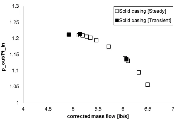
Figure 5.3: Illustration of computational strategy for parametric study using baseline axial skewed slot casing treatment ... 67
Figure 5.4: Simulated configurations with variation in slot axial position ... 69
Figure 5.5: Effect of slot axial position on rotor performance ... 69
Figure 5.6: Simulated configurations with variation in open area ratio ... 70
Figure 5.7: Effect of open area ratio on rotor performance ... 70
Figure 5.8: Simulated configurations with variation in slot skew angle ... 71
Figure 5.9: Effect of slot skew angle on rotor performance ... 71
Figure 5.10: Simulated configurations with variation in number of slots per blade passage ... 72
Figure 5.12: Simulated configurations with variation in slot stagger angle ... 73
Figure 5.13: Effect of slot stagger angle on rotor performance ... 74
Figure 5.14: Simulated configurations with variation in radial slot shape ... 75
Figure 5.15: Effect of radial slot shape on rotor performance ... 75
Figure 5.16: Simulated configurations with variation in meridional slot shape ... 76
Figure 5.17: Effect of meridional slot shape effects on rotor performance ... 77
Figure 5.18: Simulated configurations with variation in slot axial length ... 78
Figure 5.19: Effect of slot axial length on the rotor performances ... 78
Figure 5.20: Time-averaged tip clearance flow streamlines at blade tip plane for 60% AOR slots casing treatment at solid casing stalling mass flow ... 84
Figure A.1: Contours of relative Mach number at 70% span, 92% of choked mass flow operating point (near-stall point) [50] ... 95
Figure A.2: Contours of relative Mach number at 95% span, 98% of choked mass flow operating point (near peak efficiency point) [50] ... 96
Figure A.3: Mesh resolution near the casing shroud [51] ... 98
Figure A.4: Difference between the tip clearance jet and the wall speed [51] ... 98
Figure A.5: Total-to-static characteristic of the mixed flow rotor at design speed with different mesh densities ... 100
Figure A.6: Circumferentially mass-averaged total pressure and total temperature profiles at the trailing edge plane with different meshes at near stall ... 100
Figure A.7: Axial velocity contour and mesh near interface between injector and rotor subdomains ... 101
Figure A.8: Blade passage and clearance gap mesh details for both conventional (400K nodes) versus new unconventional (95K) preliminary and simulated meshes ... 103
Figure A.9: Entropy contours at the mixed flow rotor tip with new mesh at the last converged point (a) with conventional mesh and (b) with the new unconventional mesh ... 104
Figure A.10: Radial nodes distribution in the tip gap for the mesh used for casing treatment study ... 105 Figure A.11: Meshing of the casing treatment slots ... 106 Figure A.12: Contours of y+ on casing treatment slot walls ... 106 Figure A.13: Temporal pressure signal from one spatial point located inside the casing slot near
its leading edge ... 108 Figure A.14: Temporal pressure signal from one spatial point located inside the casing slot near
LIST OF SYMBOLS AND ABBREVIATIONS
Abbreviations
SM Stall margin
OAR Open Area Ratio
CGCT Circumferential Groove Casing Treatment BTLV Blade Tip Leakage Vortex
EAR Entire Annular Recess
Symbols
p Static pressure
Pt Stagnation (or total) pressure Tt Stagnation (or total) temperature
Corrected mass flow
LIST OF APPENDICES
APPENDIX A: VALIDATION OF THE COMPUTATIONAL TOOL SET-UP ... 94
A.1 Introduction ... 94
A.2 Code selection ... 94
A.3 Turbulence model selection ... 96
A.4 Mesh setup ... 97
A.4.1 Mesh for stall criteria assessment ... 97
A.4.2 Mesh setup for micro tip injection ... 100
A.4.3 Mesh setup for casing treatment study ... 104
CHAPTER 1
INTRODUCTION
1.1 Introduction
It is well known that the operational envelope of a gas turbine engine is constrained by the compression system air-flow instability which can lead to a severe drop in engine power and incur engine damage. Therefore, compressor aerodynamic stability is a major concern for the gas turbine industry.
The operating range of a compressor is described by a plot of the pressure rise characteristic versus mass flow rate, called a speedline, at different speeds, often referred to as a compressor map, as shown in figure 1.1. At a particular speed, if the mass flow rate is reduced, the pressure rise across the compressor increases until a point, usually called stall point, where an aerodynamic instability called rotating stall occurs. This instability is described by the formation of a cell of stalled fluids with meridional velocity deficiency, called a rotating stall cell, which rotates at a fraction of the compressor rotor speed, and which is usually accompanied by a sudden drop in pressure rise. When coupled to the other main components of a gas turbine, namely the combustor and the turbine, the resulting failure to maintain the pressure rise across the compressor mean that the high-pressure gas in the combustor volume can flow backward toward the front of the compressor [1]. This leads to an axisymmetric flow oscillation across the entire engine called surge, which is much more damaging in terms of performance and hardware than rotating stall itself. Since rotating stall is usually the trigger for surge, research in compressor aerodynamic instabilities, including the present one, focus on rotating stall control.
As shown on the compressor map depicted in figure 1.1, the line joining the stall point of each compressor speed is often referred to as the surge line, while the line that runs through the design point along which the compressor operates as the engine accelerates or decelerates is called the running line or operating line. The position of this line is set by the turbine. Since the shape of the running line changes with the rate of acceleration and that of the surge line changes with operational wear and with any flow non-uniformity in the incoming airflow, such as cross-wind or during aircraft maneuvers, a safety margin called surge margin, is left between the running and surge lines. However, the presence of the surge margin often means that the compressor is not
operating at the point of optimum pressure rise and/or optimum efficiency which can lie close to the stall point. Delaying stall inception to lower mass flow rate also means that the operating point could approach or reach this point while maintaining the same stall margin resulting in reduction in the engine weight (by reducing the number of compressor stages) and fuel consumption.
Figure 1.1: Compressor map
A good understanding of the physical processes responsible for the rotating stall contributes greatly to the development of optimal stall inhibition technology. Research into stall suppression technologies have been carried out for several decades. However, the development of these technologies has mostly been empirical. In fact, although there has been significant progress into rotating stall inception research, the phenomenon it still not fully understood yet. As a result, the existing stall suppression technologies often involves a trade-off between stall margin improvement and efficiency penalty at the design point, where the engine spends most of its operating time, and there are at present no general rules for their design to limit or eliminate this trade-off.
The idea behind the current research is to use the latest understanding in rotating stall inception and results from past stall suppression research to come up with general design rules to increase
stall margin without losing efficiency, especially around the design point. As illustrated in figure 1.2, the flow in even an axial compressor rotor blade passage is highly three-dimensional and quite complex. The first feature is the boundary layers on the blade and endwall surfaces that migrate normal to the streamwise direction under the effects of the blade passage turning and the centrifugal and coriolis forces to create secondary flows. Unlike the flow in a turbine blade passage, the positive pressure gradient and possible presence of shock (sudden pressure increase) can cause these boundary layers to separate either on the blade (blade stall) or in the corner (corner stall) both of which can in theory lead to rotating stall. The second feature is the flow through the clearance between the rotor tip and casing, called tip clearance flow or tip leakage flow, which interacts with the incoming flow to form a three-dimensional vortex with both low streamwise velocity and low relative total pressure in the tip region, producing a blockage that reduces the flow area and limits the diffusion of the flow through the blade passage. Research have pointed to tip clearance flow as the first responsible for the rotating stall inception, in which case the compressor is usually referred to as a tip critical compressor. Modern compressor blade design technology usually insures that boundary layer separation is not an issue, such that most modern compressor seem to be tip critical compressors. The current research will focus on stall suppression technologies as applied to tip critical compressors.
Figure 1.2: Axial compressor flow field: (a) three-dimensionality of the flow, (b) tip clearance flow (Lakshminarayana's book [2])
1.2 Compressor rotating stall inception
There are two known types of rotating stall inception: long scale (modal) and short length-scale (spike) stall inception. First theorized by Moore and Greitzer [3] and later shown experimentally, modal stall inception is characterized by the relatively slow growth of a small usually full-span disturbance of long circumferential wavelength into a fully developed rotating stall cell within 10 to 40 rotor revolutions. This disturbance rotates at roughly half the rotor speed without changing speed till the final establishment of the rotating stall cell. This is illustrated on the left plot of figure 1.3 and shown by stacked velocity traces from equally spaced probes around the compressor circumference. Modal stall has been shown to occur at or slightly past the zero-slope peak of the total-to-static pressure rise characteristics (speedline). Moore and Greitzer [3] showed that a positive slope of the total-to-static speedline means negative damping of naturally occurring perturbations causing them to grow into rotating stall. It is thus basically an instability of the entire compression system and seems to be only related to the compressor rotor tip clearance flow in so as much as how it affects the shape of the speedline through mixing losses and tip blockage [4]. The relatively slow growth of the perturbations into rotating stall implies that they can be detected and low-power counter perturbations can be applied in real time to negate their growth while their amplitude is still small. Several experiments [5, 6] have shown success for this concept, at least for a single or a small number of axial stages. Since this technology is only applied at the stall point there should be no effect on the design point performance.
However, most modern compressors stall through spike stall inception, which was discovered by Day [7] in 1993. It is characterized by the appearance of a large amplitude short length-scale disturbance (‘spike’) at the rotor tip, as illustrated on the left plot of figure 1.4, which grows very rapidly into a fully developed rotating stall cell within two to five rotor revolutions. Spike stall inception occurs at the negative slope of the total-to-static speedline, before the conditions (zero-slope) associated with modal stall inception. The short time scale involved in spike stall inception renders real-time detection and suppression virtually impossible with current technology and one must thus rely on passive techniques. However, these techniques are also active away from the stall point and may thus adversely affect compressor performance near the design point, which underlines the importance of studying and optimizing these techniques. While the true
mechanism behind spike stall inception is not yet known, a promising explanation was provided by Vo et al. [8] based on tip clearance flow. They postulate that two threshold flow events must be both present for spike disturbances to form and thus spike stall inception to occur. These are tip clearance flow spillage below the leading edge (LE) rotor blade tip, and flow reversal (“backflow”) of tip clearance fluid below the rotor trailing edge (TE) blade tip. Although other recent research tend to support this hypothesis, it has not been fully confirmed and is too recent to be taken into consideration for most of the literature on stall suppression technologies. This hypothesis will provide the starting point for the current research into optimizing suppression technologies for spike stall inception.
Figure 1.3: Modal stall inception and associated hot-wire (axial velocity) trace [7]
1.3 Stall suppression technologies
The two most promising technologies for suppressing rotating stall in tip-critical compressors are casing treatment and tip injection. Casing treatment is the most commonly applied technique and involves putting slots, grooves or recessed vane in the outer casing, above the tips of compressor rotor blades. Over the last 40 years, various forms of casing treatment have been tested for improving endwall flow and enhance compressor stability as depicted in figure 1.5. Slots and circumferential grooves casing treatments afford a path for flow to recirculate in both axial direction from the rear to the front near blade leading edge guided by the streamwise pressure gradient and in circumferential direction from the pressure side to suction side while tip injection provides additional streamwise momentum to the endwall flow. While their developments have mostly been by trial and error, it is now recognized that all casing treatments forms (slots, grooves or tip injection) energize the endwall flow field. For example slots casing treatments remove low momentum fluid at the rear and blow it at the front. Previously, the main drawback that casing treatments faced was the loss in compressor peak efficiency which is found to be proportional to stall range increase. Recently, some researchers reported that slots casing treatment placed in a more forward position over an axial compressor rotor may operate without loss in efficiency. However, there are no systematic design rules for casing treatment to achieve lossless casing treatment with acceptable stall margin improvement. In the absence of a detailed understanding of the flow mechanisms behind rotating stall and how stall inhibition techniques such as casing treatments affect these mechanisms, such design rules are essential to the effort of designing optimal casing treatment. Since casing treatment usually involve highly unsteady flows that required extensive simulation time and resources, even a computational parametric study to obtain such rules have so far been too expensive to be contemplated. Tip injection involves injection of high-speed flow near the casing of the compressor to delay stall, as illustrated in figure 1.6. While this technique has shown success [9] the amount of air required in traditional tip injection, which would have to be taken from the rear of the compressor, will penalize engine efficiency. This factor and the mechanical integration involve in terms of piping and valves may explain why this technique has been restricted to the laboratory. Recent research into micro-injection [10, 11], in which a very small amount of injected air aimed almost exclusively at the tip clearance region, has shown very promising results and opens the door to
this technology being used with no or negligible engine performance loss. However, the possibility of clogging and associated preventive maintenance requirements remains a hurdle for the practical implementation of micro-injection technology.
Given the practical inconvenience of tip injection technology, this research will place more emphasis on pursuing casing treatment technology.
(c)
Figure 1.5: Different Casing treatment configurations (a) Axial-skewed slots casing treatment, (b) Blade angle slots casing treatment, (c) Circumferential grooves casing treatment
r
θ
Figure 1.6: Tip air injection principle
1.4 Mixed-flow compressors
Continuous flow (turbomachinery) compressors usually come under two types: axial and centrifugal compressors. The axial compressor stage is composed of a rotor and a stator across which the fluid is mainly flowing in the axial direction with very little change in mean radius. On the other hand, a centrifugal compressor stage is composed of an impeller across which the fluid enters axially but goes through a large change in radius and typically exits in the radial direction with a very large amount of swirl. A diffuser is then used to turn the flow back into the axial direction. The large radius change implies that centrifugal compressors can deliver much higher pressure ratio per stage than axial compressors, but the flow in them is much more complex with higher levels of aerodynamic losses (lower compressor adiabatic efficiency). As such, the axial compressor has so far been widely used in aero-engines for higher efficiency at the cost of using many more stages. The wider aeronautical application of axial compressors coupled with the relatively simpler flow field means that the majority of research into stall inception and stall suppression technologies concentrated on axial compressors.
A hybrid design between the axial compressor and the centrifugal compressor, called mixed flow compressor, has found its way into recent small gas turbine engines. As illustrated in figure 1.7, it is similar to an axial compressor with the exception that it has a larger chord with a more
Rotor blade
Tip air injection Tip clearance flow
significant change in mean flow radius across the rotor. As such, the rotor would have a much lower aspect ratio and deliver significantly higher pressure ratio per stage than axial compressors, allowing for lower stage count. Inversely, the change in radius renders the flow relatively more complex with more radial displacement of low-velocity blade boundary layer fluid toward the blade tip and as such increases tip loss and lowers efficiency. There is virtually no research carried out on this type of compressor. The only exception is the recent empirical study by Qiang et al. [12] of casing grooves on a mixed flow compressor. Thus, there is a need to establish stall prediction capability and casing treatment design methods/rules for this type of compressor that may, in the latter case, be also applicable to axial compressors.
Figure 1.7: Meridional and 3D view of a mixed flow compressor stage [12] Stator
1.5 Research questions
The relevant research questions for the current project are threefold: - What are the stall criteria for mixed flow compressors?
- Can we design a casing treatment for a mixed flow compressor to increase its surge margin without negative impact on peak efficiency?
1.6 Thesis objectives
Based on the above research questions, the objectives of the current project are: 1) Determine stall prediction criteria for mixed flow compressors
2) Provide preliminary casing treatment design rules for mixed flow compressors to enhance stall margin without loss in compressor efficiency around the design point. To meet these objectives, a literature review on past research into stall inception mechanism and stall suppression technologies for axial compressors is first carried out and assessed. Simulations are then carried out on a modern aircraft mixed flow compressor rotor geometry to establish the stall criteria for this type of compressor. Finally, a baseline casing treatment geometry is proposed for this compressor rotor based on past research into axial compressors. A new method is then devised to efficiently carry out for this rotor the most complete parametric study of casing treatment design so far (for any compressor) in order to establish preliminary design rules for design of an optimal casing treatment.
1.7 Thesis outline
The structure of the present thesis is described as follows. Chapter 2 contains a literature review on stall suppression techniques that could be separated into five main configurations, namely slots, circumferential grooves, recess-vanes and self-recirculated casing treatments and tip air injection and ends up with important conclusions that constitute the starting point for the current work. Chapter 3 exposes the general methodology. Chapter 4 presents the computational setup and results for the stall criteria study. Chapter 5 presents in detail the methodology and results for the casing treatment study. Finally, the conclusions and proposed future work are given in chapter 6.
CHAPTER 2
LITERATURE REVIEW
2.1 Introduction
This chapter presents a literature review of relevant and recent research on stall inception and passive stall suppression technologies, in particular casing treatments and tip air injection. The chapter starts with a brief review of the research into the mechanisms associated with rotating stall inception. Subsequently, a review on the three main categories of casing treatment technologies, namely slots, circumferential grooves and recirculation endwall casing treatments is presented. Thereafter, the literature review continues with tip air injection technologies. The chapter concludes with a summary of the main findings from the literature review.
2.2 Stall inception research
The first attempt to physically explain the development and evolution of rotating stall dates back to the early 1950’s. Emmons [2] was the first to postulate a scenario for rotating stall in axial compressors. He stated that once a blade passage stalls through suction side boundary layer separation due to an instantaneous increase in incidence at the blade LE, a blockage represented by a deficiency in the streamwise velocity will then favour the adjacent blade passage to reduce its incidence and stabilize while the other one, in the opposite direction to the rotor rotation, will see its incidence increase and therefore will subsequently stall in turn as shown in figure 2.1. This process will be sequentially repeated for each blade passage and will move in a direction opposite to rotation in the relative frame, and at part of the rotor speed in the stationary frame.
Figure 2.1: Propagation of rotating stall in axial compressors [4]
However, it is well known that compressors can operate with large regions of separated flow over the blade without imminent compressor instability. Moore and Greitzer [3] presented a comprehensive model of the compressor stability by combining 1-D and 2-D compressor instability theories. The 1-D model corresponds to surge-like behaviour which considers the entire compression system which is made up by the compressor, upstream and downstream ducts (flow inertia), plenum chamber (mass storage) and throttle valve as illustrated in figure 2.2. The mechanical analogy in the form of mass-spring-damper is also shown. When the mass flow is reduced, by closing the throttle valve, beyond the zero-slope of the compressor characteristic, the pressure in the plenum does not fall as rapidly as the pressure rise in the compressor. The compressor no longer produces the pressure necessary to contain the air in the plenum which will flow back through the compressor and the system becomes unstable. The presence of ducts leads to internal lag processes in the compression system shifting therefore the occurrence of surge instability to lower mass flow in the positive slope of the compressor characteristic. Furthermore, the 2-D model deals with the non-axisymmetric instabilities associated with rotating stall. The authors demonstrated that the growth of 2-D axisymmetric small amplitude waves appropriate to rotating stall are inherent to the compressor system when the stagnation-to-static pressure rise reaches zero slope. As previously discussed, this route to rotating stall is known as the long-wavelength or modal stall inception characterized by the growth of a small amplitude full-span
perturbation with circumferential wavelength in the order of the compressor annulus within 10 to 40 rotor revolutions into a fully developed rotating stall cell. Modal stall inception was measured and suppressed successfully by real-time feedback control via a set of independent movable inlet guide vanes by Haynes et al., [13] on a three stage low-speed axial compressor.
Figure 2.2: Simple compression system with a corresponding mechanical analogue [1]
Less than a decade after the Moore-Greitzer model, Day [7] experimentally investigated rotating stall inception in a low-speed compressor and discovered that it can stall after the formation of a short-length scale, roughly three blade passage wide, large amplitude disturbance at the rotor tip, called ‘spike’, which grows very rapidly within roughly three rotor revolutions into fully developed rotating stall. This new type of spike stall inception is known as short length-scale or spike rotating stall inception, and seems to be the most common type in modern compressors. Unfortunately, their limited circumferential wavelength and very high growth rate makes detection and real-time feedback control practically impossible, thus forcing reliance on passive control techniques such as casing treatment.
Compressor Plenum Throttle Duct L Mass of fluid in duct Compressibility of fluid in plenum Damping due to compressor ~ can be negative Damping due to throttle ~ always positive Mass of fluid in throttle (small)
Gong et al., [14] extended the Moore-Greitzer model by including 3D nonlinear effects in a multi-stage compressor by means of Euler equations for simulating the development of both long and short wavelength compressor instabilities. Individual blade rows were represented by a body force formulated in terms of the blade’s pressure rise and turning characteristic. They successfully simulated a spike stall inception and development of full rotating stall occurring on the negative-slope part of the compressor characteristic in agreement with experimental measurements. The only drawback of their model is the requirement of a localized disturbance of sufficient amplitude to initiate the stall inception process (i.e. the origin of the spike is not given). However, the results mentioned above do not address the early stall inception, i.e., the spike formation processes. In this context, Hoying et al., [15] looked at the flow physics responsible for the occurrence of spike stall inception in the blade passage and specifically to the tip gap region. With computational simulations, they observed the tip clearance vortex spilling ahead of the leading edge plane of the rotor blade, resulting in spike-type stall in a fraction of the annulus using eight blade passages. Later, Vo et al., [8] refined the previous criterion for spike stall inception by stating that it is tip clearance fluid, rather than the tip vortex, that spills into the adjacent passage as illustrated in figure 2.3-a. They also added a second criterion, shown in figure 2.3-b, which concerns the trailing edge backflow of tip clearance fluid originating from the adjacent blade passage that moves upstream, below the blade tip, and impinges on the rear pressure side surface.
As illustrated in figure 2.3-c, Vo et al. [8] postulated that the movement of the interface between the incoming and tip clearance flows ahead of the leading edge plane opens a low-flow-resistance passage to allow this backflowing fluid (which would otherwise be forced into the adjacent tip clearance or to convect downstream) to continue toward the leading edge and amplify, leading to the formation of a spike disturbance. Thus, they stipulated that spike stall inception can occur only if these two criteria are present and that the last (lowest mass flow) converged solution of inexpensive single blade passage simulations can be used to evaluate these criteria and predict spike stall inception, as shown in figure 2.3-d and 2.3-e. In figure 2.3-d, the leading edge tip clearance spillage criterion is satisfied when the interface at the blade tip plane between the low-entropy incoming flow and the high-low-entropy tip clearance flow reaches the leading edge plane, especially on the pressure side, marking the onset of tip clearance flow spillage. Figure 2.3-e
blade tip
Onset of backflow below blade tip
(point (4)) VX TE / UTIP Percent S pa n 3 5
plots the spanwise distribution of mass flow at the trailing edge plane, for which a zero value at the blade tip indicates the onset of tip clearance backflow (and impingement) below the blade tip.
Figure 2.3: Proposed criteria and mechanism for spike stall inception in axial compressors and their quantitative evaluation [4]
(c)
(a)
(d)
(b)
Deppe et al. [11] investigated spike stall inception on three low-speed single-stage axial compressors and gave further experimental support to the criteria of Vo et al. [8]. They utilized highly sensitive pressure probes to demonstrate that spike stall inception is characterized by unsteady spill forward of the rotor tip clearance flow ahead of the rotor and is initiated by unsteady spots of axial backward directed flow just downstream of the rotor trailing edge close to the casing. Figure 2.4 illustrates both criteria using oil visualization technique on the outer casing wall of an axial compressor cascade corresponding to the rotor of one of the tested compressor stages at the stall point.
Figure 2.4: Experimental visualisation of the endwall flow in an axial compressor cascade at stall [16]
As for transonic compressors, the leading edge spillage was experimentally evidenced by the work of Cameron [17] as shown in figure 2.5 by using fine particles of chalk to indicate the casing shear. The chalk was continuously transported with the oil by the shear stress at the oil surface while the compressor was operating. From the position of the incoming/tip clearance flow interface at the casing (measured by the upstream zero-shear-stress line) at a point on the verge of stall, they deduced by calculation the position of this interface at the blade tip span and showed
Tip clearance flow
spillage at LE Tip clearance
backflow at TE and impingement
that it is at the blade tip leading edge plane thus confirming the first criterion of Vo et al., [8] in a transonic axial compressor.
Figure 2.5: Chalk surface visualization on casing of axial transonic compressor rotor at stall point: 1) zero shear stress line (interface), 2) reverse flow region, and 3) trailing ege bifurcation
line [16]
More recently, Hah et al., [18] simulated the stall inception of a modern transonic rotor known to stall via spike with full annulus unsteady LES (Large Eddy Simulations) and they demonstrated that the criteria proposed by Vo et al., [8] are still valid for transonic axial compressor.
2.3 Casing treatments stall suppression technologies
Casing treatment consists of incorporating slots or grooves, as shown in figure 2.2, in the rotor shroud (and/or stator hub, if there is a stator hub clearance), to passively add momentum to the endwall flow by air recirculation from high to low-pressure zones within or near the blade passage to improve performance. This section can be divided in three sub-sections dedicated to each one of the following three general types of casing treatment: slots, grooves and recess vanes casing treatments.
1
2
3 Interface at blade LE
2.3.1 Slots casing treatments
Slots casing treatment consists of placing a series of discrete slots on the casing above the rotor. The slots can be axial or rotated with or against the direction of stagger of the rotor. They can also be radial or skewed (inclined circumferentially) in the direction with or against the direction of rotor rotation. The slots can also be of varying shape either in the radial or circumferential plane and their axial position, axial extent, number and open area ratio are all geometric design parameters that can be varied.
Prince et al. [19] initiated the first reported attempts to take a comprehensive, physics-based approach to understanding the mechanism associated with casing treatment effectiveness. Their tests of different configurations of circumferential grooves, skewed slots, and blade angled slot casing treatments showed that compressibility considerations are not essential to the effectiveness of casing treatments. The interesting thing is that when they included a baffle in the middle of the axial skewed slots to prevent recirculation in the axial direction they improved the efficiency or the compressor as shown in figure 2.6. In addition, they reported that radial holes or perforated endwall treatments do not provide any benefit in terms of stall margin improvement.
Figure 2.6: Axial skewed casing treatment with baffle in the middle of the slots [18] Baffle
Fujita and Takata [20] tested different configurations of axial, skewed, and circumferential groove casing treatments, which had been shown by previous investigators to have the greatest stall range potential or exhibited the least efficiency decrement. Their results, which are consistent with past measurements, clearly show that the more effective the casing treatment is in extending the stable compressor operating range, the greater the efficiency penalty as illustrated in figure 2.7. Takata and Tsukuda [21] were the first to report clear evidence of the importance of the orientation of skewed slots on stall range and performance. Their results indicate that the greatest range extension for skewed axial slots is when the slots are skewed opposite to the rotor rotation as shown in figure 2.8, whereas skewing the slot in opposite direction (i.e. in the direction of rotor rotation) results in a drop in the flow range even when compared to the reference case without casing treatment.
Figure 2.8: Impact of orientation of the skewed slots on the performance of the rotor [21]
Smith and Cumpsty [22] applied axial skewed slots to a low-speed axial compressor with the same skewed slots design as was used by Prince et al., [19]. When they varied the clearance gap from 1% to 6% of tip clearance normalized by the tip chord, they reported that the axial skewed slots appeared to be effective in desensitizing the impact of tip clearance in the stable operating range as depicted in figure 2.9, which is consistent with the finding of Fujita and Takata [20]. Their explanation for stall range improvement was focused on the accumulation of endwall blockage that triggers the stall, with casing treatments, a path for recirculation is provided to low momentum fluid to enter slots but the overriding characteristic of casing treatments is the flow path between the pressure and suction surface.
Figure 2.9: Static pressure rise at various tip clearances for the solid wall and the treated builds [22]
Lastly, numerous additional studies of the reliability of casing treatment have emerged with the growth of CFD and the advent of high-speed computing as discussed below.
In an unpublished thesis, Seitz [23] investigated experimentally and numerically axial slot casing treatment for a subsonic compressor exhibiting spike stall inception. He conducted a series of parametric tests for the forward-positioned axial skewed slot casing treatment to assess the effect of varying slot skewed angle from 0º to 60º. He concluded that casing treatment with no loss (or even an increase) in rotor efficiency is possible when axial skewed slots extend well upstream of the rotor leading edge. He found that the maximum stall margin improvement with no loss of efficiency was 28%* for the case of a 60º skew angle when the treatment slots extend 75% axial chord upstream and 25% downstream of the rotor leading edge. For this optimum skew angle an
* Unless indicated otherwise, the stall margin improvement is defined in this report as the reduction in stalling mass
increase in peak efficiency of 1.1% was recorded when the upstream axial extent was reduced to 55% of axial chord. At this condition stall margin improvement was 20%. He related the gain in efficiency with the forward-positioned axial skewed slots to the reduction of the recirculated mass flow inside slots compared to the conventional axial skewed slots. In addition, he concluded that suction, in the downstream half of the slot, is the primary mechanism for stall delay for axial skewed slots located in the unconventional position while blowing, in the upstream half of the slot, is secondary but neither suction nor blowing are as effective at improving the stall margin as the full treatments are, irrespective of their axial positions. Furthermore, the deleterious effect of blowing is counteracted by the positive effect of suction resulting in no loss in efficiency for the unconventional treatment.
For transonic compressors, Wilke et al. [24] carried out a numerical investigation on Rotor 37 which reveals that the effectiveness of casing treatments depends very much on the aerodynamics of the compressor inflow and the specific flow mechanisms at conditions close to stall. Their simulations with the slots casing treatment as illustrated in figure 2.10 show that axial slots directly impact the flow mechanisms responsible for compressor stall, which were referred to as “blade tip stall” and “tip blockage stall”. The former mechanism refers to suction side boundary layer separation in the blade tip region from high incidence/loading. The latter mechanism refers to increase in tip blockage due perhaps to tip vortex breakdown. The stall margin improvement was approximately 5.5% with a drop in peak efficiency of about 0.4%. Their work indicates that the effectiveness and impact on compressor efficiency of axial slots mainly depend on their axial position over the blade tips. On the one hand, the more upstream the slots are positioned the less their negative impact on the compressor efficiency will be. In the other hand, the more upstream slots the less the extension in stall mass flow.
Figure 2.10: Slots casing treatment configuration [24]
Lu et al. [25] examined experimentally and numerically for a subsonic compressor different type of slots casing treatments (blade angle slot, bend skewed slot, axial skewed slot, circumferential grooves), and demonstrated the practicality of employing CFD simulations to expediently and economically conduct an array of parametric studies on the effects of casing treatment design parameters. They used unsteady CFD simulations with axial skewed slot casing treatment to illustrate the intermittent, time-dependent nature of the recirculating flow pattern for discrete slot endwall casing treatments. They found that circumferential grooves are not as effective as the axial skewed slots casing treatment because the circulation inside the slots is much stronger than circumferential grooves. This finding is consistent with other previous works. They also indicated that the mechanism by which the casing treatments postpone the inception of the stall instability is that they prevent an early spillage of low momentum fluid into the adjacent blade passage. Lin et al, [26] carried out both experimental and numerical investigations of a slot-type casing treatment with a recess chamber on a transonic axial flow compressor rotor, as shown in figure 2.11. Their experiments show that at 60% and 98% of rotor design wheel speeds, approximately 26.5% and 20.16% in stalling mass flow reduction were achieved, respectively. On the other hand, there were about 3.4% and 0.7% drops of efficiencies at 60% and 98% speeds respectively. For the treated casing case, the passage shock near the blade tip is oblique relative to the incoming flow (as shown in figure 2.11) and its strength is reduced, thus, the shock loss and the reversed flow on the endwall behind the shock are reduced. Consequently, the incidence and the
loading at blade tip region are reduced. They concluded that the interactions between the blade passage flow and the casing treatment flow exhibit different behaviour at two rotating speeds. The flow condition in which the rotor operates, i.e., either the subsonic condition at the 60% speed or the transonic condition with passage shock presented at the 98% speed, explains the difference in the improved performances of the rotor since the alteration of the shock strength and its location brings additional improvement in the performances in terms of pressure rise and isentropic efficiency as well.
Figure 2.11: Effects of the casing treatment slots on the passage shock structure and the geometrical design of the casing treatment slots [25]
(Solid casing) (Treated casing)
(Design of casing treatment slots) Oblique shock Detached
Emmerich et al. [27] investigated numerically and experimentally casing treatment with axial skewed slots ending in a plenum chamber for a highly subsonic compressor similar to Lin et al., [26]. Their experimental results show a stall margin improvement of approximately 18.5 %, while the design efficiency decreases by 1.4 %.
In an extension to the work of Wilke et al., [24], Brignole et al, [28] examined numerically the effects of four different semi-circular axial skewed slots casing treatments on a transonic compressor stage, as shown in figure 2.12, in order to identify correlations between cavity geometries and the passage flow. The tested configurations are; 1) standard skewed slots, 2) narrow skewed slots with a small open area in the casing, 3) curved skewed slots with elliptic shape of the slots with the same open area as for the narrow slots case, and 4) short skewed slots with a small axial extent of the slots. The results showed an improvement in efficiency at design conditions of up to 0.6% for the narrow slots configuration and a raised total pressure ratio at both 100% and 80% speed with reduction of 10.7% in stalling mass flow rate. The gain in efficiency was found to correlate to the relative amount of mass entering the casing treatment and especially to the effectiveness of the geometry to induce a recirculation across the entire cavities. In addition, the simulations showed a decrease in the endwall secondary flow by a reduction of three-dimensional flow phenomena originating in the rotor tip clearance, improving thus the stall margin of the compressor stage. Furthermore the rotor loading was enhanced in the tip region, resulting in a higher pressure ratio.
Figure 2.12: Slots casing treatment configuration [28]
2.3.2 Circumferential grooves casing treatments
Circumferential groove casing treatments consist of adding circumferential recesses in the casing above the rotor. The shape of the recess, depth, number, axial location and axial extent are geometric design parameters that can be varied.
In the case of circumferential grooves for subsonic compressors, Nezym [29] carried out a parametric experimental investigation of entire annular recess (EAR) casing treatment over the compressor rotor blades where various forms of grooves were used. He reported on the benefit of using a penetration (figure 2.13a) and rectangular recess extending from the leading edge to the trailing edge of the rotor with the casing radius at the same value as that of the rotor tip (figure 2.13b). He concluded that the larger recess depth and volume, the more the stable operating range. For the former case with a penetration, he could obtain an improvement in the operating
range of 35% when compared to the configuration without treatment, and 22% for the second configuration
(a) (b)
Figure 2.13: Two effective variants of the EAR (Entire Annular Recess) (a) penetrating casing treatment and (b) blade tips coincide with the casing baseline [29]
For high speed compressors, Muller et al. [30] reported on an experimental and numerical investigation of circumferential grooves in a transonic single-stage axial compressor with four different groove configurations characterized by deep and shallow grooves and variable coverage of the projected rotor axial chord, as shown in figure 2.14. The authors demonstrated a significant increase in operating range with all configurations with an improvement of 9.6% in the stall mass flow for the best configuration which corresponds to 6 deep grooves. However, shallow grooves were less effective. They noticed that while deep grooves roughly maintained efficiency levels compared to the smooth wall case, shallow grooves had a beneficial effect in increased stage peak efficiency at design speed by more than one percent. Independently from the groove depth, they proved that a higher coverage of the rotor projected axial chord seems favourable for delaying stall inception to a lower mass flow (six grooves against three grooves, i.e. twice the axial extent, as shown in figure 2.14). For this compressor, spike stall inception was deduced from measurements upstream of the leading edge.
(a) (b)
Figure 2.14: Circumferential grooves position (a) 6 gooves and (b) 3 grooves, deeper shallow for each [30]
Another casing treatment investigation on Rotor 37 transonic has been done by Zhang and Ma [31] using sloped circumferential groove, as shown in figure 2.15. When compared to the smooth casing, the results show that this geometry provides a barrier to minimize the forward flow from the tip clearance vortex, that seems to be associated with spike stall inception. Furthermore, they show the entropy interface which lines up with the leading edge plane at stall which corresponds to one of the two criteria proposed by Vo et al., [8]. Their stall margin improvement is approximately 1% with almost no drop in efficiency (≈ 0.2%).
Huang et al., [32] studied the performance of Rotor 37 (transonic compressor) with circumferential grooves casing treatment (CGCT). They used different configurations of CGCT using only one groove G1 to all in same time from G1 to G7 as shown in figure 2.16. Two critical flow structures with different tip clearance at near stall condition were revealed. With the designed small tip clearance, the leading edge tip leakage flow driven by the pressure gradient has high momentum to make the leading edge BTLV (Blade Tip Leakage Vortex) strong enough to avoid from breakdown before the occurrence of other unstable structures, for example the trailing edge separation. But if the separation is suppressed by the casing treatment, the leading edge BTLV breakdown happens with a higher back pressure. When the tip clearance increases, the tip leakage flow joined to the BTLV gets weak due to the decreasing of the pressure gradient in the tip clearance. That may lead to the BTLV having not enough energy to get through the passage shock and breakdown before the full development of trailing edge separation. For these two typical stall relating structures, circumferential grooves at the mid-chord or near the leading edge were effective, respectively. Benefit on stall margin has been achieved without obvious efficiency penalty in the present computational results. However, they did not present the compressor’s characteristic to extract the stall margin but they obtained 11.75 % in stall margin improvement based on a definition of stall margin given here as:
0 0 100 1 peak stall TR TR stall peak P P m m SM
WherePTR means the total pressure ratio and m the mass flow rate.
Mileshin et al., [33] studied numerically the performances of a transonic axial stage, and near-surge rotor tip clearance flow has been performed for small and large rotor tip clearances and for large tip clearance equipped with 8 circumferential grooves used like a casing treatment. They concluded that grooves diminish mass flow in the circumferential direction through tip clearance gap and locate tip leakage vortex trajectory deeply within blade-to-blade channel. It increases surge margin. They got approximately 2% reduction in the stalling mass flow. However, they did not discuss about the gain in efficiency.
![Figure 1.2: Axial compressor flow field: (a) three-dimensionality of the flow, (b) tip clearance flow (Lakshminarayana's book [2])](https://thumb-eu.123doks.com/thumbv2/123doknet/2329007.31204/22.918.116.794.688.924/figure-axial-compressor-flow-field-dimensionality-clearance-lakshminarayana.webp)
![Figure 2.3: Proposed criteria and mechanism for spike stall inception in axial compressors and their quantitative evaluation [4]](https://thumb-eu.123doks.com/thumbv2/123doknet/2329007.31204/34.918.113.803.199.1000/figure-proposed-criteria-mechanism-inception-compressors-quantitative-evaluation.webp)
![Figure 2.4: Experimental visualisation of the endwall flow in an axial compressor cascade at stall [16]](https://thumb-eu.123doks.com/thumbv2/123doknet/2329007.31204/35.918.190.784.436.747/figure-experimental-visualisation-endwall-axial-compressor-cascade-stall.webp)
![Figure 2.6: Axial skewed casing treatment with baffle in the middle of the slots [18] Baffle](https://thumb-eu.123doks.com/thumbv2/123doknet/2329007.31204/37.918.395.646.643.1006/figure-axial-skewed-casing-treatment-baffle-middle-baffle.webp)
![Figure 2.8: Impact of orientation of the skewed slots on the performance of the rotor [21]](https://thumb-eu.123doks.com/thumbv2/123doknet/2329007.31204/39.918.215.706.123.371/figure-impact-orientation-skewed-slots-performance-rotor.webp)
![Figure 2.9: Static pressure rise at various tip clearances for the solid wall and the treated builds [22]](https://thumb-eu.123doks.com/thumbv2/123doknet/2329007.31204/40.918.279.639.115.497/figure-static-pressure-various-clearances-solid-treated-builds.webp)
![Figure 2.10: Slots casing treatment configuration [24]](https://thumb-eu.123doks.com/thumbv2/123doknet/2329007.31204/42.918.168.761.114.324/figure-slots-casing-treatment-configuration.webp)
![Figure 2.20: Nozzle arrangement of single stage subsonic compressor with different aspect ratio [11]](https://thumb-eu.123doks.com/thumbv2/123doknet/2329007.31204/56.918.248.660.526.842/figure-nozzle-arrangement-single-subsonic-compressor-different-aspect.webp)