Science Arts & Métiers (SAM)
is an open access repository that collects the work of Arts et Métiers Institute of
Technology researchers and makes it freely available over the web where possible.
This is an author-deposited version published in: https://sam.ensam.eu Handle ID: .http://hdl.handle.net/10985/10303
To cite this version :
Jean-Frederic CHARPENTIER, N. FADLI, J. JENNANE - Study of Ironless Permanent Magnet Devices Being Both a Coupling and an Axial Bearing for Naval Propulsion - IEEE
TRANSACTIONS ON MAGNETICS - Vol. 39, n°5, p.3235-3237 - 2003
Any correspondence concerning this service should be sent to the repository Administrator : archiveouverte@ensam.eu
Study of Ironless Permanent Magnet Devices
Being Both a Coupling and an Axial Bearing
for Naval Propulsion
J. F. Charpentier, Member, IEEE, N. Fadli, and J. Jennane
Abstract—This paper describes the study of an original perma-nent magnet device. This device works as both a coupling and as an axial bearing. It can be particularly useful in naval propulsion application to transmit the torque without any contact between a motor axis and the propeller and to maintain the propeller in its axial position, compensating the axial force related to thrust. Two kinds of devices are studied for this type of specification. The first corresponds to the classical structure of cylindrical air-gap cou-pling. The second is an original structure where pairs of rings of axially magnetized magnets are stacked on each rotor. The compu-tation of the behavior of the device (torque and axial force) is done using a semi-analytical method based on magnetic charge theory. This method allows a very fast calculation of the performances of the devices. This study shows the interest of the stacked structure for this type of application.
Index Terms—Magnetic coupling, permanent magnet, magnetic bearing, magnetic charges, naval application.
I. INTRODUCTION
P
ERMANENT magnet (PM) couplings are more and more used in industrial applications to transmit a torque without any contact between a leading and a led rotor. This type of de-vice is used to transmit a torque through a separation wall or to avoid failure due to torque overload. It can be useful in naval propulsion to transmit a torque between the axis of the motor and the propeller of a boat with a total insulation (Fig. 1). In the case of a cylindrical air-gap coupling, the device is stable in the axial direction [1]. So a small displacement of the propeller in the axial direction leads to an axial force that is opposed to this displacement. Therefore, such a device can be used as a cou-pling to transmit the motor torque and as a passive axial bearing to maintain the propeller in its axial position, compensating the axial force related to thrust.Thus, the device must have a big pull-out torque (maximal torque) and a big axial stiffness to maintain the propeller in its axial position. In this paper, two types of cylindrical air-gap devices are studied. These devices consist of two rotors. In these two rotors, paralelepipedical magnets are stuck on ironless cores. The ironless cores allow us to reduce inertia and to use original configurations in which iron yokes can
J. F. Charpentier is with the Research Institute of the French Naval Academy (IRENav) F-29240 BP 600 Brest Armees, France (e-mail: charpentier@ecole-navale.fr).
N. Fadli and J. Jennane are with the Ensem of Casablanca BP 8118, Oasis Casablanca, Morocco.
Fig. 1. Device principle.
reduce significantly the performance of the device (use of axial magnets).
To study these devices, it is necessary to calculate the force and the torque exerted by the first rotor on the second rotor as functions of the axial and angular shift between the two rotors. This computation allows evaluation of the performances of the device for this type of application. The classical way to calculate the performances of such a device is the three-dimensional finite element method. However, this method is very heavy in terms of complexity and calculation time (many calculations must be done to evaluate the performance of the coupling as a function of the two variables and of the device dimensions).
In this paper, a semi-analytical method based on magnetic charge theory is used to do a fast and efficient study of this type of device.
II. DEVICESDESCRIPTION
Two kinds of ironless devices are studied for this application. In these devices, the magnet dimensions are the same in both rotors.
A. First Kind of Device
The first is based on the classical structure of a passive PM cylindrical air-gap coupling. In this device, the leading and led rotors are built with alternated (north and south) permanent magnets with radial magnetization. These magnets are stuck on ironless cores. This classical structure is shown in Fig. 2.
Fig. 2. First kind of structure.
The main characteristic dimensions for this first structure are: the magnet thickness , the magnet length , the air gap, the average radius of the air gap, and the number of pairs of poles. B. Second Type of Device
A second type of device is also studied. In this original struc-ture, a set of pairs of magnet rings are stacked on each rotor. Each magnet ring is built with paralepipedical PMs with alter-nated axial magnetization. Fig. 3 shows a six-poles device with one and two pairs of magnet rings rotor. The main characteristic dimensions of this second kind of structure are the magnet rings thickness , the total length occupied by the magnet rings , the number of ring pairs, and the number of pole pairs.
III. TORQUE ANDFORCESCALCULATION
The torque (T) and the axial force ( ) exerted between the two rotors are computed by the calculation of the magnetic forces exerted between each magnet of the leading rotor on each magnet of the led rotor.
(1) and are the tangential and axial compo-nents of the force exerted by the ith magnet of rotor 1 (leading rotor) on the jth magnet of rotor 2 (led rotor). is the average radius of the jth magnet of rotor 2.
The calculation of the force exerted between two magnets of the structure is performed by the use of magnetic charge theory. According to this theory, a parallelepipedical magnet with a par-allel magnetization can be considered like two charged planes with a magnetic charge density is the magnet mag-netization and is the plane normal vector. Therefore, the force
exerted by magnet i on magnet j can be seen as
(2) where is the magnetic field created by magnet on the two charged planes of magnet ( and , which are, respectively, charged with and ). For a parallepipedical magnet, the field can be expressed analytically [2]. So (2) can be computed using a numerical integration method such as
Fig. 3. Second type of structure (6 poles).
the Gauss and Labotto integration method [3]. This computa-tion method allows the calculacomputa-tion of the magnetomechanical performances of the devices with a good precision and a very small calculation time [4].
IV. SIMULATIONRESULTS
The structures have been studied for the same set of main characteristics dimensions: same magnet volume and
magneti-zation ( cm cm, T); same
av-erage radius of the mechanical air gap (12 cm); and air gap value (3 mm). It corresponds to the same magnet weight and same en-velope dimensions. To avoid demagnetization problems, NeFeB magnets with very high coercivity must be used for this appli-cation (as an example, Sumitomo Neomax 28EH can be used successfully in this type of device under 100 C).
The isovalues of axial force (dashed line) and torque exerted on rotor 2 by rotor 1 (solid line) are shown as functions of the angular shift and the axial shift between the two rotors for a ten-pole pairs structure. The results are given in Fig. 4 for the first type of structure and for the second kind of structure, for one, two, and three pairs of magnet rings per rotor. Hori-zontal and vertical axes correspond, respectively, to angular shift in degrees and axial shift in millimeters. The zero angular po-sition corresponds to the torque stable popo-sition. The zero-axial position corresponds to the zero-zero-axial force stable position where the magnets of rotor 1 are facing the magnets of rotor 2. The operating point for a given small boat propeller
specifica-tion is shown ( N m and N).
It can be noticed that, for the classical structure, the pull-out torque is important (around 70 N m). Furthermore, the axial stiffness appears to be very small. So the axial shift corre-sponding to the operating point is very big (more than 4 mm). This means that there is a risk for the propeller to be pulled out of the axis if there is an overload. For the second structure, the
Fig. 4. Force and torque for four types of structure.
stiffness appears to be much bigger than in the first one. The operating points corresponding to the second type of structure with 1, 2, and 3 pairs of magnet rings by rotor lead to axial shifts of 1.7, 0.6, and 0.7 mm, respectively. The corresponding pull-out torques are 56, 49, and 29 N m for the three cases. It means that a stacked structure with two pairs of rings of axially oriented magnets appears to be much more efficient in term of axial stiffness than the classical one and allows us to transmit the specified torque with a good safety margin.
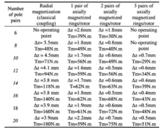
Table I gives the values of the axial shift corresponding to the operating point (20 N m, 200 N) and the values of the pull-out torque Tm (maximal torque that can be transmitted by the device at ) for the four types of structure (radial
TABLE I
OPERATINGPOINTAXIALSHIFT ANDPULL-OUTTORQUE
magnetization, 1, 2, and 3 pairs of axially magnetized rings by rotor). These values are given as functions of the number of pole pairs for the same set of characteristic dimensions. The classical structure leads to big values of torque for high number of pole pairs. However, the number of pole pairs have only a very small influence on the axial force and stiffness of this structure. That means that the classical radial structure is interesting in terms of transmitted torque, but is not very advantageous in terms of axial force. The second type of structure with two pairs of mag-netized ring per rotor leads to small axial shifts for the operating point with good values of pull-out torque. That means that if the device has to compensate a big axial force and to transmit a big torque, a structure with two or three rings of axially magnetized magnet by rotor can be a very advantageous solution.
V. CONCLUSION
In this paper, two kinds of PM magnetomechanical devices are studied using a semi-analytical method. These devices work both as a coupling and as an axial bearing for naval applications. They allow to transmit the torque from the motor axis to the propeller of a boat and to maintain the propeller axially, com-pensating the force related to thrust. The study shows that an original structure of device where some pairs of rings of alter-nated axially magnetized PMs are staked on each rotor can be very advantageous for this type of application.
REFERENCES
[1] J. Delamare, E. Rulliere, and J. P. Yonnet, “Classification and synthesis of PM bearing configurations,” IEEE Trans. Magn., vol. 31, pp. 4190–4192, Nov. 1995.
[2] G. Akoun and J. P. Yonnet, “3D analytical calculation of the forces ex-erted between two cuboidal magnets,” IEEE Trans. Magn., vol. 20, Sept. 1984.
[3] T. N. L. Patterson, “One gauss and labotto based integration formulae,” Math. Comput., vol. 22, pp. 877–881, 1968.
[4] J. F. Charpentier and G. Lemarquand, “Calculation of ironless PM cou-plings using semi-numerical magnetic pole theory method,” Compel, vol. 20, no. 1, pp. 72–89, 2001.