HAL Id: hal-00620859
https://hal.archives-ouvertes.fr/hal-00620859
Submitted on 9 Sep 2011
HAL is a multi-disciplinary open access archive for the deposit and dissemination of sci-entific research documents, whether they are pub-lished or not. The documents may come from
L’archive ouverte pluridisciplinaire HAL, est destinée au dépôt et à la diffusion de documents scientifiques de niveau recherche, publiés ou non, émanant des établissements d’enseignement et de
Fretting-corrosion between 316L SS and PMMA:
Influence of ionic strength, protein and electrochemical
conditions on material wear. Application to orthopaedic
implants
Julie Pellier, Jean Geringer, Bernard Forest
To cite this version:
Julie Pellier, Jean Geringer, Bernard Forest. Fretting-corrosion between 316L SS and PMMA: In-fluence of ionic strength, protein and electrochemical conditions on material wear. Application to orthopaedic implants. Wear, Elsevier, 2011, 271 (9-10), pp.1563-1571. �10.1016/j.wear.2011.01.082�. �hal-00620859�
Fretting-corrosion between 316L SS and PMMA: influence of
ionic strength, protein and electrochemical conditions on material
wear. Application to orthopedic implants.
J. Pellier, J. Geringer
*, B. Forest
École Nationale Supérieure des Mines de Saint-Étienne (ENSM-SE), Centre Ingénierie & Santé, UMR CNRS 5146 PECM, IFR 143 IFRESIS, 158 cours Fauriel, 42023 SAINT-ETIENNE cedex 2, France
Received Date Line (to be inserted by Production) (8 pt)
Abstract
In biomedical field, fretting-corrosion between 316L SS femoral stem and bone cement is one of the significant causes of the hip prosthesis loosening. This article investigates wear by fretting-corrosion at the contact between 316L and PMMA . The influences of the ionic strength (NaCl solutions from 10-3 to 1 mol.L-1), a model protein (albumin) and electrochemical conditions on contact behaviour are studied. At OCP (Open Circuit Potential) conditions, the chlorides concentration, i.e. the ionic strength, increases the 316L wear; and albumin, concentration of 1g.L-1, does not play a significant role in total 316L wear. At cathodic applied potential E = -400 mV(SCE), a threshold concentration of 10-1 mol.L-1 (NaCl solution), Cth, indicates
two behaviours: a protective effect below Cth, and an additional anodic dissolution above Cth. One might suggest that, beyond
Cth, the passive layer is not efficient for protecting against the corrosion. At this potential, albumin reduces wear due to
corrosion and amplifies mechanical wear induced by corrosion. Albumin seems to act as an anodic inhibitor. To determine the mechanisms of synergism, a “more cathodic” potential is applied, E = -800 mV(SCE), during fretting-corrosion experiments. Consequently, the corrosive wear can be neglected and the mechanical wear can be only measured.
Keywords: Fretting-corrosion, 316L SS, PMMA, Ionic strength, Albumin.
1. Introduction
In Europe, each year, there are about 1 million hip replacements, and approximately the same number in USA. Nevertheless, after 10-15 years, approximately 10% of Total Hip Arthroplasties (THA) need a reintervention. Nowadays, the ageing of the population, injuries or diseases like arthrosis are public health issues. To avoid additional surgical reoperation and improve lifetime duration of implants, studies on orthopedic implants
are needed. Three different metal alloys can be used for femoral stem: cobalt–chromium alloy, titanium alloy or austenitic stainless steel. We focus our attention on cemented hip prostheses. In 1960, in order to decrease the number of femoral stem debonding, Sir John Charnley decided to insert hip prostheses with poly(methyl methacrylate) called bone cement [1]. For a cemented prosthesis (Fig. 1), the austenitic stainless steel (316L SS alloy) is usually used for femoral stem thanks to its biocompatibility and high resistance against corrosion in biological environment without friction.
Because of the daily human gait and significant difference of mechanical properties (particularly, Young's moduli) between 316L SS and bone cement, stress shielding phenomenon appears. The metallic material and the polymer do not have the same strain properties, thereby leading to debonding between the femoral stem and the cement. It involves fretting (friction under small displacements, term precisely defined later) and friction. Finally, the upper part of femoral bone is unloaded and then becomes more susceptible to fracture; on the other hand, if bone around femoral stem tip is overloaded, it becomes stronger [2]. However, the bone cement acts as a “bumper” between femoral stem and bone, leveling peak forces acting around the prosthesis during the human gait.
Fig. 1 Total hip joint cemented prosthesis components
Femoral stem debonding and consequently friction between femoral stem and bone cement leads to cement degradation and cracking (Fig. 1). Debris from bone cement and femoral stem (metal oxides and ions) go through cement up to bone tissues [3]. Thus, the disturbance of osteoblasts cell activity and the tissue inflammation, respectively caused by bone cement particles and metallic oxides and ions, involve implant reoperation. It is the reason why fretting-corrosion between femoral stem and bone cement, particles generation, is one of the most
important causes of reintervention [4,5]. Consequently, fretting-corrosion experiments were carried out for understanding corrosion and mechanical influences, and improving the lifetime of implants.
Fretting means friction under small reciprocal displacements, and the amplitude of displacement is lower than contact width. Rubin et al. found out, by numerical modeling, the amplitude of displacement is about 50 µm (depending on the location) between bone and stem under applied stresses during human gait [6]. Nonetheless, the displacement amplitude between bone cement and femoral stem is supposed identical [7].
Wear of a metallic material under the conjugated effects of a mechanical solicitation (friction or fretting in this case) and of corrosion by a medium (physiological liquid) is named tribocorrosion [8]. Thus, fretting-corrosion is fretting in a corrosive environment for a metal alloy. This phenomenon leads to passive layer destruction and debris generation, principally metal oxides (Fig. 2) and polymer particles [9-11].
The corrosion phenomenon between femoral stem and bone cement is modelized by fretting-corrosion between a 316L SS sample (the same material as that of femoral stem) and PMMA which has the same mechanical properties as bone cement. This polymer was chosen because of its optical transparency. In that way, a direct observation of the contact zone and the debris evolution between materials at contact are investigated.
Fig. 2 (a) Fretting-corrosion between femoral stem (Exeter V40TM) and bone cement [7]; (b) fretting-corrosion between a head (316L) and a femoral neck (Ti-6Al-4V)
Physiological liquid components are various, including numerous ions and proteins. Each component plays a different role in double layer constitution at material surface. To separate the contribution of each component, fretting-corrosion tests between 316L and PMMA were investigated in different solutions. The first one is Ringer solution. Its composition is close to physiological liquid. However, this solution is too complex: each ion may
a)
during a fretting-corrosion test. To compare corrosion and mechanical behaviours in these solutions, this study aims at investigating the influence of ionic strength I:
i i iC z I 2 2 1 (1)where zi: ion charge; Ci: ion concentration. Indeed, the ionic strength can interfere in the double layer constitution
by the solution content and in the “attraction-repulsion” phenomenon betweenthe contact between two materials [12].
The role of proteins is also investigated. This work focuses on albumin, which is the main protein of blood plasma. Afonso et al. [13] have shown that bovine serum albumin, in NaCl 0.15 M at 37 °C, on UNS S31254 stainless steel, stops anodic dissolution of chromium and decreases iron dissolution. Valero Vidal et al. [14]
worked with 316L and CoCrMo alloy in NaCl 0.14 M at 37 °C, with or without albumin (0.5 g.L-1). They showed
that for 316L, albumin does not modify open circuit potential (OCP) but it acts as an anodic inhibitor at applied potential, i.e. it increases cathodic reaction rate. Albumin also tends to decrease the polarization resistance, removing oxides from a protective layer and then exhibiting a material surface from corrosion. For CoCrMo alloy, albumin acts as a cathodic inhibitor and also increases anodic reaction rate, i.e. it accelerates corrosion. During a fretting-corrosion test between a Ti-6Al-4V alloy and alumina in pH buffered saline solutions at 37 °C, Hiromoto et al. [15] showed that albumin (1 g.L-1 bovine serum albumin) mostly modifies cathodic behaviour and acts as a cathodic inhibitor, i.e. it reduces cathodic reaction rate. From a mechanical point of view, albumin does not affect friction coefficient µ and wear volume.
During a fretting-corrosion test, material wear is a combination of mechanical wear (fretting) and corrosion. However, the total material loss(W) is not only determined as the sum of two different material losses: (i) material
loss due to mechanical wear obtained without the influence of corrosion(Wm) and (ii) the material loss due to
corrosion obtained without fretting action(Wc). There is a synergistic effect between corrosion wear and
mechanical wear. The synergy term(W) means that corrosion increases wear due to fretting(Wcm) and friction
increases wear due to corrosion(Wmc) [16,17].
W = Wm + Wc + W = Wm +Wc + (Wcm + Wmc) (2)
This work aims at understanding the role of mechanical action and corrosion on a synergy term, and also calculating each of these terms for a fretting-corrosion test. In a first place, we focus on the percentage of wear
due to corrosion obtained from the wear volume due to corrosion Vcorr (cm3), and the percentage can be found out
with Faraday’s law:
t i n M F V with W V wear
corrosive corr corr * * * 1 100 * % (3)
where F is Faraday constant (F = 96500 C.mol-1), M is the molecular weight (M = 56.39 g.mol-1), n is the number of electrons involved in the anodic process (n = 2, hypothesis), t is the total duration of the fretting-corrosion test
(t = 14,400 s), is density ( = 8 g.cm-3
) and i (A) is the difference between the average current during fretting and the current after fretting.
Three electrochemical conditions were investigated for this study. First, the Open Circuit Potential (OCP) condition allows being as close as possible to the in vivo conditions. However, no information on current is available at OCP. Thus, fretting-corrosion tests are also carried out at cathodic applied potentials. -400 mV(SCE) is a threshold potential for anodic and cathodic transition of current. To remove (or to neglect) corrosion and to
only obtain mechanical wear (Wm), the cathodic potential of -800 mV(SCE) is chosen. For each electrochemical
condition, the role and the influence of albumin are investigated.
2. Materials and methods
2.1 Materials
The 316L femoral stem is modeled by a plane 316L SS sample: 9 mm x 9 mm x 20 mm parallelepiped. One of the flat parts (9 mm x 20 mm) was polished with diamond paste down to 1 µm. This frictional surface exhibits
3D roughness(Sa) of about 10 ± 2 nm (area of 1 x 2 mm, VeecoTM optic profilometer).
The bone cement, involved in THA, is modeled by a cylindrical PMMA, a polymer which has the same mechanical properties as those of bone cement. A sample maintains the length of 15 mm and the radius of
curvature of 10 mm. The cylindrical face was polished with 3 µm diamond solution, Altuglass Polish 1 and 2® and
colloidal solution of silica (particles size of 0.06 µm). The 3D roughness (Sa) is about 35 ± 5 nm.
The geometry of the contact, cylinder/plane, allows a better control of contact pressure and width. Before the fretting-corrosion test, 316L SS and PMMA samples were stored at least 24 hours in a desiccator. The 316L sample is electrically insulated with Zircalloy alloy sheets and some varnish.
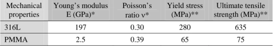
The composition of the 316L austenitic stainless steel (X2CrNiMo17-12, improved cleanliness and very low carbon content) is in accordance with ISO standard 5832-1 (Table 1). Mechanical properties of both materials are shown in Table 2.
Table 1 Chemical composition of 316 L stainless steel
Elements Cr Ni Mo Mn Si Co C Cu S Fe
Table 2 Mechanical properties of tested materials: 316L stainless steel and PMMA, *: obtained by ultrasonic measurements; **: manufacturer data Mechanical properties Young’s modulus E (GPa)* Poisson’s
ratio * Yield stress (MPa)**
Ultimate tensile strength (MPa)**
316L 197 0.30 280 635
PMMA 2.5 0.39 65 75
2.2 Solutions
Two types of solution are used: Ringer solution (composition in Table 3) and NaCl solution, with
concentrations of 10-3, 10-2, 10-1 and 1 mol.L-1. Room temperature was of 22 ± 1 °C. To understand influence of
proteins on fretting behaviour, albumin of 1 g.L-1 was added in each saline solution.
Table 3 Ringer solution composition
NaCl KCl CaCl2 NaHCO3
Concentration (g.L-1) 8.50 0.25 0.22 0.15
2.3 Test device
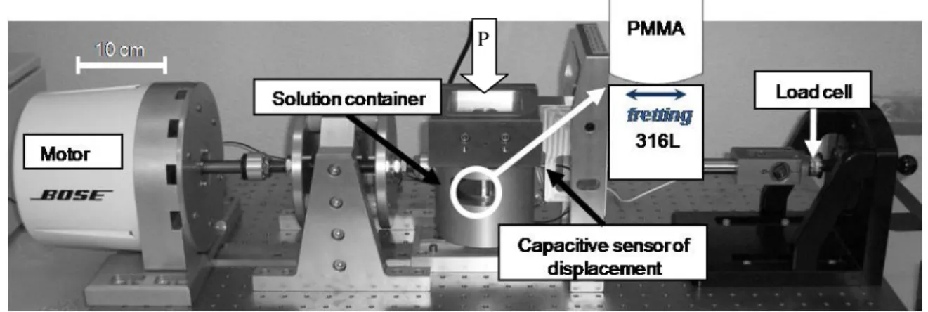
To reproduce fretting-corrosion phenomenon, micro-displacements measured in vivo (about 50 µm) and stresses applied in vivo (between 7 and 30 MPa) [6] must be replicated. A specific device (Fig. 3), conceived and developed in collaboration between ENSM-SE and Böse, was used for fretting-corrosion tests. An electromagnetic motor, first tried for fretting-corrosion, let us obtain the same results as those delivered by the device used previously [9-11]. The load cell is a piezoelectric transducer and the displacement measurer is a capacitive sensor.
The mechanical parameters of fretting-corrosion tests are realistic:
the applied normal load (P) was 127.5 N, i.e. a pressure of about 22 MPa, which is spread from 7 to 30 MPa, range of pressure applied in vivo [6];
the amplitude of displacement was ± 40 µm, close to the in vivo displacement [6]. Moreover, the displacement is sinusoidal and the frequency is 1 Hz, i.e. one cycle equals one second, corresponding to the frequency of the gait cycle.
For these mechanical values, the gross slip condition was checked.
To identify actual displacement between both materials, the accommodation of the device must be
considered. Based on the hypothesis that there is an elastic behaviour with compliance Cs, the actual displacement
is: = r – acc = r – Cs * Q, where r and acc are respectively the monitored and accommodated displacements,
2.4 Electrochemical measurements
For electrochemical measurements (OCP), current density and Electrochemical Impedance Spectroscopy (EIS), a PARSTAT 2263 potentiostat with a three-electrode set up was used:
the working electrode was the stainless steel sample,
the counter electrode was a circular wire of Pt having the diameter of about 60 mm,
the reference electrode was a Saturated Calomel Electrode (SCE, E = +246 mV(SHE) at T = 22 °C).
Fig. 3 Fretting-corrosion device: ENSM-SE and Böse prototype
EIS measurements were investigated from 105 Hz to 10-1 Hz at a rate of 10 measurement frequencies/decade,
with an AC amplitude of 10 mV. The potential was equal to OCP determined before EIS measurements or to applied potential (-400 or -800 mV(SCE) in our case). During friction tests, because of the non-stationarity conditions, EIS measurements should not be performed for actual values, but only the evolution of electrical parameters was considered [19]. One may notice that regular EIS measurements, during the fretting phase, have no influence on OCP or on current values after the EIS measurements.
For each electrochemical condition, OCP or cathodic applied potential (-400 and -800 mV(SCE)), two experiments (steps defined in Table 4) were carried out for all solutions with or without albumin.
Table 4 Electrochemical measurements steps for each electrochemical conditions, OCP or cathodic applied potentials (E = -400 or -800 mV(SCE)) Electrochemical conditions OCP Potential applied: -400 or -800 mV(SCE)
Step 1 Cathodic polarization: -1 V(SCE), 5 min
Step 2 without fretting: 1 h + EIS without fretting: 10 min + EIS
Step 3 with fretting: 4 h + 10 EIS regular distribution
Step 4 without fretting: 14 h + 2 EIS after
fretting stop and 1 EIS after 14 h
without fretting: 10 min + 2 EIS
after fretting stop
Step 5 without fretting: 14 h OCP
measurement and 1 EIS after 14 h 2.5 Wear profiles
Thanks to VeecoTM WYKO NT9100 optic profilometer, the measurements of the total wear volumes for 316L
and PMMA were performed. Three measurements were carried out on 316L and PMMA surfaces. The total wear volume was thus extrapolated for the total wear track length (15 mm). This value was compared with the total wear made on the whole length of the track. The wear volume error is about 10 %. Raw data were filtered by an automatic cylindrical shape.
3. Results
3.1 Open Circuit Potential conditions
3.1.1 OCP evolution
After cathodic polarization of 5 min at -1 V(SCE), the open circuit potential (OCP) is recorded without fretting during 1 hour (steps described in Table 4, OCP evolution on Fig. 4). From the beginning of fretting, OCP is significantly decreased and then slightly stabilized. Instantly after the end of fretting, OCP nearly recovers the
value before fretting. At regular intervals (every 20 minutes), the polarization resistance (Rp) is determined with
Electrochemical Impedance Spectroscopy (EIS) in order to investigate the behaviour of the metal surface. Rp is
extracted from the simple electrical circuit: Rsol(CPE//Rp), Rsol is the solution resistance, CPE is a Constant Phase
Element and Rp is the polarization resistance (resistances of the passive layer and the double layer at high
Fig. 4 Detail of experiment: OCP measurement before, during and after fretting and Rp measurements from EIS. Rp:
difference between Rp before and Rp after 2400 cycles of fretting; OCP: difference between OCP before fretting (Ebf) and
OCP at the end of fretting (Eff). Solution is constituted by NaCl 10-3 mol.L-1, displacement amplitude is of ± 40 µm, 1 cycle is
equal to 1 second
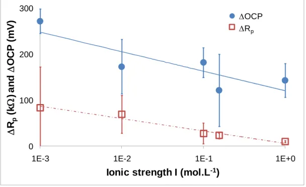
Fig. 4 exhibits OCP and Rp values in a NaCl solution of 10-3 mol.L-1. It is worth noting OCP and Rp
evolutions are the same as those of other solutions, only OCP and Rp vary in accordance with the different
solutions (Fig. 5).
Fig. 5 exhibits the decrease of OCP and Rp according to the ionic strength. Both electrical values are
consistent and they are related to the evolution of the contact submitted to fretting, i.e. less passive behaviour of the AISI 316L SS.
3.1.2 Mechanical behaviour
From a mechanical point of view, the dissipated energy (Ed) during one cycle, which corresponds to the
mechanical work of the tangential force, was monitored. For the total duration of the test, the cumulated dissipated
energy (Edc), i.e. the sum of Ed for each cycle (1 cycle = 1 second), was calculated. The cumulated dissipated
energy during fretting increases with ionic strength (Fig. 6). One may notice that experiments were investigated at two compliances. This fact substantiates that, the dissipated energy variation is controlled by the composition of the solution, not the mechanical device.
0 100 200 300
1E-3 1E-2 1E-1 1E+0
R
p(k
) a
nd
OC
P
(
m
V
)
Ionic strength I (mol.L
-1)
OCP Rp
Fig. 5 Rp: difference between Rp before fretting and 2400 cycles after fretting start; and OCP: difference between OCP
before fretting (Ebf) and that at the end of fretting test (Eff) versus ionic strength I
90 100 110 120
1E-3 1E-2 1E-1 1E+0
Cu m u la te d di s s ipa te d e n e rgy E dc (J )
Ionic strength I (mol.L
-1)
Fig. 6 Cumulated dissipated energy Edc during the fretting-corrosion test in a function of ionic strength I. Two compliances
were investigated, : Cs = 0.0707 µm.N -1 and : Cs = 0.2563 µm.N -1
: C
s= 0.0707 µm.N
-1
: C
s= 0.2563 µm.N
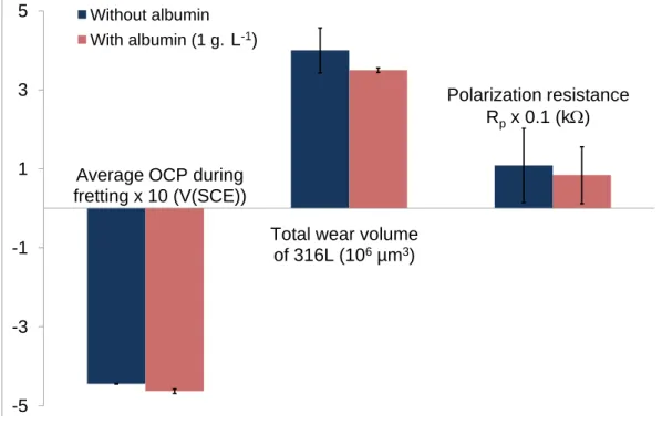
-1-5 -3 -1 1 3 5 Without albumin With albumin (1 g.
Average OCP during fretting x 10 (V(SCE))
Total wear volume of 316L (106µm3) L-1)
Polarization resistance Rpx 0.1 (k)
Fig. 7 Influence of albumin (1g.L-1) at OCP conditions on average OCP during fretting, the total wear volume of 316L SS and polarization resistance for NaCl 1 mol.L-1
3.1.3 Albumin influence
In order to satisfy in vivo conditions and to understand the role of proteins, experiments were carried out in the same electrochemical conditions and the same solutions with the presence of a protein: albumin with a
concentration of 1 g.L-1. As shown on Fig. 7, albumin has no influence (ANOVA test, = 0.05) on the average
value of OCP during fretting and the total material loss for NaCl 1 mol.L-1. Edc, OCP and Rp are not
significantly different in cases with and without albumin in NaCl 1 mol.L-1. The same conclusion is highlighted in
other solutions. Nevertheless, albumin has influence on wear volume of PMMA: this one is slightly lower with albumin.
3.1.4 SEM images
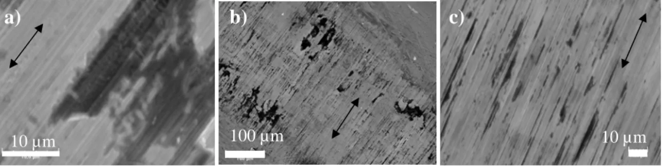
Worn surfaces of 316L SS were observed with a Scanning Electron Microscope (SEM) 6400 JEOL combined with an Energy Dispersive X-Ray (EDX) probe. Fig. 8 presents surfaces of 316L samples submitted to fretting-corrosion tests. Corrosion crevices (Fig. 8 a) are mostly localized at the border of the wear track (Fig. 8 b). At 1
Fig. 8 SEM images of 316L SS in NaCl 1 mol.L-1 (a), (b) without albumin (c) with albumin, arrows show the direction of sliding
3.2 Cathodic applied potential conditions (E = -400 mV(SCE))
At OCP conditions, although we are close to the in vivo conditions, no information on current is available. That’s why the second part of this work focuses on cathodic applied potential, and more specifically E = -400 mV(SCE). This value was chosen because the influence of ionic strength on current during fretting can be highlighted.
3.2.1 Evolution of the current
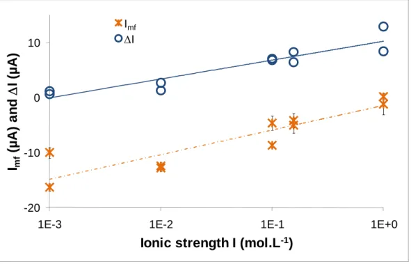
Significant values, as the average current during the last 3 hours of fretting (Imf),I, the difference between
the current at the end of fretting (Iff) and the current after fretting (Iaf), were investigated in accordance with ionic
strength. As shown on Fig. 9, fretting involves a higher impact on current values for NaCl solution of 1 mol.L-1
(I ~ 11 µA) than that for NaCl solution of 10-3
mol.L-1 (I ~ 1 µA): the applied potential is enough to protect a
surface during friction phase for NaCl 10-3 mol.L-1. In the same way, Imf is close to zero and is even positive, i.e.
anodic for one experiment at NaCl 1 mol.L-1 even though it is cathodic (~ -15 µA) for NaCl 10-3 mol.L-1.
100 µm
10 µm
10 µm
-20 -10 0 10
1E-3 1E-2 1E-1 1E+0
I
mf(µ
A
) an
d
I (
µ
A
)
Ionic strength I (mol.L
-1)
Imf I
Fig. 9 Average current during fretting-corrosion, Imf, and difference between current at the end of fretting (Iff) and that after
fretting (Iaf), I versus ionic strength I
3.2.2 Wear volume evolution
As described in §2.5, wear volumes were measured on PMMA and 316L samples with the VeecoTM 3D optic
profilometer (Fig. 10). Wear volume of PMMA is constant whatever the ionic strength (ANOVA test, = 0.05) at OCP and E = -400 mV(SCE) is, but the wear volume of PMMA is slightly higher at OCP conditions.
1 µm 0 µm -1 µm 2 µm 1 µm 0 µm -1 µm -2 µm
a)
b)
Fig. 10 3D wear profiles of (a) 316L and (b) PMMA, in NaCl 1 mol.L-1 at OCP conditions, image size of 1x1 mm2
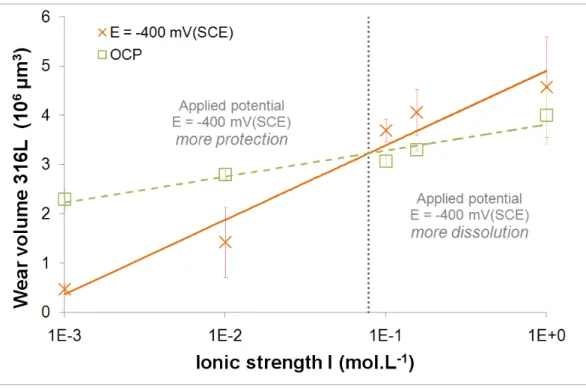
As illustrated on Fig. 11, for 316L samples, total material loss increases with ionic strength for both
electrochemical conditions. A threshold concentration is then highlighted, about 10-1 mol.L-1. For 10-3 and 10-2
mol.L-1, wear volume measured in OCP conditions is higher than that for E = -400 mV(SCE). Moreover, for
concentrations above 10-1 mol.L-1, wear volume measured in OCP conditions is lower than that at E = -400
mV(SCE).
Fig. 11 Total wear volume of 316L versus ionic strength for OCP conditions and E = -400 mV(SCE)
3.2.3 Albumin influence
Contrary to OCP conditions, albumin plays a significant role at the cathodic applied potential of E = -400 mV(SCE). Mainly, two values are analyzed: the average current during fretting and the percentage of corrosive
wear. In NaCl 1 mol.L-1 (Fig. 12), albumin largely (ANOVA test, = 0.05) reduces the current during fretting
(from ~ -0.5 µA without albumin to ~ -10 µA with albumin) and the percentage of corrosive wear (from ~ 80 % without albumin to ~ 50 % with albumin). One may suggest that albumin acts as an anodic inhibitor, as shown by Valero Vidal et al. [14].
-10 0 45 60 80 Without albumin With albumin (1 g. Average current during fretting (µA)
% of corrosive wear L-1)
Fig. 12 Influence of albumin (1g.L-1) at E = -400 mV(SCE) on average current during fretting and the percentage of corrosive wear of 316L SS for NaCl solution of 1 mol.L-1
3.2.4 SEM images
At E = -400 mV(SCE), the main difference between Fig. 13 a and Fig. 13 b, i.e. NaCl 1 mol.L-1 with or
without albumin, concerns the grooves inside crevices. Without albumin, grooves indicate that pulled out particles are enough hard to damage surfaces. With albumin, no groove is observed into crevices: particles are probably
softer or are ejected more rapidly. At NaCl 10-3 mol.L-1 (Fig. 13 c), the central zone of the contact is not damaged
and localized corrosion is not observed.
100 µm
10 µm
10 µm
3.3 Cathodic applied potential conditions (E = -800 mV(SCE))
To neglect wear due to corrosion and to obtain wear due to mechanical wear (Wm), the cathodic potential of
-800 mV(SCE) was chosen. To validate this potential value, only extreme ionic strengths (10-3 and 1 mol.L-1) were
tested.
Table 5 Average current during fretting Imf and total wear volume W measured at E = -800 mV(SCE), with or without albumin.
Influence of albumin and ionic strength is determined by an one-way ANOVA test ( = 0.05)
Imf (µA) Albumin
influence?
W (106 µm3) Albumin
influence?
without albumin with albumin without albumin with albumin
10-3 mol.L-1 -17.60 ± 0.30 -14.93 ± 0.32 YES 0.25 ± 0.07 0.19 ± 0.03 NO
1 mol.L-1 -27.96 ± 9.31 -45.57 ± 3.11 YES 0.38 ± 0.14 0.35 ± 0.08 NO
Ionic strength
influence? NO YES NO NO
As shown on Table 5, the average of current during fretting varies in a function of ionic strength and is modified by the presence or not of albumin. However, the total wear volume is same without regard to the condition (ionic strength and albumin). One may assume that the total wear volume equals the mechanical wear
volume Wm , i.e. Wm = 0.3 ± 0.1 106 µm3.
4. Discussion
4.1 Open Circuit Potential conditions
The evolution of OCP before, during and after fretting is shown on Fig. 4. One may notice that Ebf
logarithmically decreases with the ionic strength in accordance with [20]. Chloride ions, Cl-, accelerate anodic
dissolution with the formation of an unstable compound MCln (or M(H2O)yClx) [21]. At high concentration of
chloride ions, one may suggest that metallic dissolution is higher and leads to OCP decrease.
The drastic drop of OCP occurs as soon as fretting starts (Fig. 4), expressing the surface degradation. The passive layer on 316L surface is partly destroyed and metal dissolution, i.e. anodic reaction, occurs. In addition,
breakdown of the passive layer is highlighted by the polarization resistance (Rp) fall. Rp is indeed inversely
proportional to corrosion rate (Stern-Geary equation): the Rp fall involves acceleration of corrosion.
One may notice that these falls, OCP and Rp, decrease with the ionic strength (Fig. 5). According to
Macdonald [22], when the concentration of Cl- increases, the passive layer reconstruction becomes more and more
difficult. The result highlighted on Fig. 5 translates the difficulty of passive layer reconstruction during fretting when chlorides concentration increases.
The OCP and Rp upturn, directly after cessation of fretting (Fig. 4), confirms corrosion activation during
fretting test. However, the OCP value after fretting is lower than Ebf. The electrochemical behaviour of 316L
surface can indeed be modified by the less protective worn zone and the PMMA and oxides debris deposed on the 316L surface.
From a mechanical point of view, it is worth noting that the cumulated dissipated energy (Edc) during the
fretting test increases with the ionic strength (Fig. 6). One may suggest that when the ionic strength increases, attraction between surfaces is reinforced [23].
As shown on Fig. 7, albumin has no influence on the average OCP during fretting and on total wear volume of 316L. Without friction, Valero Vidal et al. [14] showed that albumin does not modify OCP values. At this
concentration, 1 g.L-1, albumin does not modify electrochemical behaviour: it has no influence on OCP during
fretting and Rp values; nor on total wear volume.
4.2 Cathodic applied potential conditions (E = -400 mV(SCE))
The applied potential E = -400 mV(SCE) is a cathodic potential, i.e. the current is negative, thus the surface is
protected against corrosion. However, this protection is not effective for all solutions. For example, in NaCl 10-3
mol.L-1, this protection is effective: I ~ 1 µA while it is not effective in NaCl 10-1 or NaCl 1 mol.L-1, respectively
I ~ 7 µA and I ~ 11 µA (Fig. 9). During the fretting-corrosion test, the current even becomes positive, i.e.
anodic, for NaCl 1 mol.L-1. In fact, a threshold concentration and two surface behaviours can be determined (Fig.
11). For concentrations below 10-1 mol.L-1, wear volumes at OCP condition are higher than those at E = -400
mV(SCE): the applied potential protects surface. For concentrations above 10-1 mol.L-1, wear volumes at OCP
condition are lower than those at E = -400 mV(SCE): the metal dissolution is higher and the passive layer is less protective against fretting.
1E-1 1E+0 1E+1
1E-3 1E-2 1E-1 1E+0 1E+1
T
o
ta
l w
e
a
r
v
o
lu
m
e
W
(
1
0
6µm
3)
Wear due to corrosion V
corr(10
6µm
3)
Without albumin With albumin
corrosive wear only:
W = Vcorr
(1 g.L-1)
Fig. 14 The total wear volume of 316L SS, W, as a function of wear due to corrosion, Vcorr, in the logarithmic scale. The
dashed straight line: case where wear is only due to corrosion W = Vcorr. Ionic strength decreases from the right to the left
Fig. 14 allows underlining which of preponderant wear phenomena is highlighted: corrosion or mechanical wear. Experimental data close to the dashed straight line indicate preponderance of corrosive wear. Corrosion is
also the preponderant wear phenomenon for high ionic strength: ~ 80 % in NaCl 1 mol.L-1 and 10-1 mol.L-1
without albumin. One may notice that, in presence of albumin, the percentage of wear due to corrosion decreases:
~ 50 % in NaCl solutions of 1 mol.L-1 and 10-1 mol.L-1, instead of 80 % without albumin. Especially, in the
presence of albumin and for lower ionic strength, standard deviation values are large and the coefficient of variation is in the range from 10 to 100. The preponderant phenomenon is mechanical wear and in this case, the dispersion of corrosive and total wear values is larger. The main mechanical degradation, under albumin and NaCl solutions, should involve hazardous wrenching that should be related to the high standard deviation.
4.3 Cathodic applied potential conditions (E = -800 mV(SCE))
As explained in §1, the total wear volume of 316L SS is the sum of wear due to corrosion, Wc. and
mechanical wear, Wm. The total wear volume, W, follows the equation (2). At E = -800 mV(SCE), no anodic
current is measured during a fretting-corrosion test. In this electrochemical condition, anodic dissolution, i.e. metallic dissolution, is neglected without regard to ionic strength and the presence of albumin. The mechanical
wear Wm is also determined: Wm = 0.3 ± 0.1 106 µm3. At E = -400 mV(SCE), thanks to Faraday’s law, the wear
due to corrosion Vcorr can be calculated (equation (3)). In fact, in comparison with the total wear volume (equation
(2)), Vcorr = Wc + Wmc. By deduction, the term Wcm can be determined, as a function of ionic strength at E =
-400 mV(SCE). To set apart the synergy term W = Wmc + Wcm, the term Wc must be measured. From
polarization resistance values, the dissolution current of the material, i, can be calculated: i = B/Rp, with B = 24
mV (hypothesis coming from investigations in the COST 533 round robin). In that way, Wc is ~ 100 or 500 µm3
depending on the ionic strength. Wc represents only 0.01% of Vcorr and this can be neglected. Iwabuchi et al.
found the same ratio: Wc/W of ~ 0.01% [25].
Fig. 15 a illustrates the contribution of Wmc, i.e. the increase of corrosive wear due to fretting. Levels can be
defined from NaCl solution of 10-1 mol.L-1 without albumin: above this concentration, the contribution of
corrosive wear is about 80%. Albumin at a concentration of 1 g.L-1 shifts the transition and the percentage of
corrosive wear: above 10-2 mol.L-1, the contribution of corrosive wear is constant and about 50%. Thus, albumin
decreases the percentage of corrosive wear. One may notice that material behaviour in Ringer solution is different from that in NaCl solutions. Because of the presence of other ions (Table 3), the contribution of corrosive wear decreases. For example, the role of carbonates could be determined in future work. Fig. 15 b illustrates the
contribution of Wcm, the increase of mechanical wear due to corrosion. No trend can be defined: mechanical
wear is not a function of ionic strength, and this term matches with an arbitrary wrenching in the surface material.
0 20 40 60 80 100
1E-3 1E-2 1E-1 1E+0
W e a r v o lu m e fr acti o n : w ear -in d u ced co rr o s io n W mc /W ( % )
Ionic strength I (mol.L-1)
Wmc/W, without albumin Wmc/W, with albumin (1g.L-1) 0 20 40 60 80 100
1E-3 1E-2 1E-1 1E+0
W ear vo lu m e fr ac ti o n : c o rr o si o n -in d u ced w ear W cm /W ( % )
Ionic strength I (mol.L-1)
Wcm/W, with albumin (1g.L-1)
Wcm/W, without albumin
Fig. 15 The contribution of the different synergy terms with albumin (empty symbols) or without albumin (full symbols) : (a) Wmc/W is the increase of corrosive wear due to fretting and (b) Wcm/W is the increase of mechanical wear due to
corrosion
Diomidis et al. [26] worked with a new expression of synergy term. Synergism is in fact the acceleration of material deterioration by corrosion because of mechanical removal and re-growth of a passive layer. Continuous and intermittent sliding tests are completed to measure the material loss in the sliding track. The intermittent sliding tests allow the removal and re-growth of the passive layer. However, the sliding conditions in a
In future work, the influence of albumin concentration on metal behaviour will be studied. To be closer than in vivo conditions, experiments will be realized at 10 and 20 g.L-1. For example, the ISO standard indicates a
concentration of proteins equal to 17.5 g.L-1 for improving the lifetime of hip implants [27,28].
As seen on Fig. 10 a, the characteristic shape of 316L wear track, ‘W’ wear shape as mentioned in [9,10], is the consequence of crevice corrosion. The evolution of local pH might lead to this particular shape. The influence of pH solution could give some information on the crevice corrosion effect. The crevice corrosion effect will be investigated in further investigations.
5. Conclusions
Under OCP conditions, the increase of chlorides concentration leads to higher corrosion and a more difficult
passive layer reconstruction during the friction phase. From a mechanical point of view, the Edc increases
according to the ionic strength; consequently one might suggest attraction between surfaces is reinforced.
At E = -400 mV(SCE), a threshold concentration, around 10-1 mol.L-1, highlights that a surface protective
phenomenon occurs below this concentration, while more metal dissolution appears above this value.
At E = -800 mV(SCE), only the mechanical wear is determined: Wm = 0.3 ± 0.1 106 µm3. This value is
needed to calculate the term of synergy between corrosive and mechanical wear.
Albumin, at 1 g.L-1, has no influence at OCP conditions. However, at E = -400 mV(SCE), the percentage of
corrosive wear is lower in presence of albumin. Albumin seems to play the role of an anodic inhibitor.
When the chlorides concentration, i.e. the ionic strength in this study, increases, the 316L wear increases too. The most interesting result is: albumin promotes the mechanical degradation compared with the corrosive wear, under cathodic polarization. This assertion includes the pure mechanical degradation and the synergism mechanical wear assisted by the corrosion. One might suggest this synergistic term should be the key-point of the 316L wear, under cathodic polarization.
Acknowledgements
The authors wish to acknowledge Saint-Etienne Métropole and Conseil Général de la Loire for the financial support. Moreover the authors thank Pr. D.D Macdonald for fruitful discussions and Dr. Kim about reviewing of the English language.
References
[1] J. Charnley, The long-term results of low-friction arthroplasty of the hip performed as a primary intervention, The Journal of bone and joint surgery. British volume 54 (1972) 61–67.
[2] G. Joshi, S.G. Advani, F. Miller, M.H. Santare, Analysis of a femoral hip prosthesis designed to reduce stress shielding, Journal of Biomechanics 33 (2000) 1655–1662.
[3] F. Langlais, Prothèses totales de hanche. Facteurs biologiques et mécanismes de tolérance, in: F. Langlais, J.P. Delagoutte, Cahiers d’enseignement de la SOFCOT n°44, Expansion scientifique française, 1993, pp. 3–22.
[4] P. Kovacs, J.A. Davidson, K. Daigle, Correlation between the metal ion concentration and the fretting wear volume of orthopaedic implant metals, Particulate debris from medical implants: mechanisms of formation and biological consequences, ASTM STP 1144, ASTM
International, 160–176, 1997.
[5] R.B. Waterhouse, Occurrence of fretting in practice and its simulation in the laboratory, Materials evaluation under fretting conditions, ASTM STP 780, S.R. Brown, 3–16, 1982.
[6] P.J. Rubin, P.F. Leyvraz, L.R. Rakotomanana, Intérêt de la modélisation numérique dans l’évaluation pré-clinique d’une prothèse fémorale de la hanche, Maîtrise Orthopédique 93 (2000) 22–27.
[7] H. Zhang, L.T. Brown, L.A. Blunt, X. Jiang, S.M. Barrans, Understanding initiation and propagation of fretting wear on the femoral stem in total hip replacement, Wear 266 (2009) 566–569
[8] P. Ponthiaux, C. Richard, F. Wenger, Tribocorrosion, Techniques de l’ingénieur, COR60, 2007.
[9] J. Geringer, B. Forest, P. Combrade, Fretting-corrosion of materials used as orthopaedic implants, Wear 259 (2005) 943–951. [10] J. Geringer, B. Forest, P. Combrade, Wear analysis of materials used as orthopaedic implants, Wear 261 (2006) 971–979. [11] J. Geringer, B. Forest, P. Combrade, Wear of poly (methyl methacrylate) against a metallic surface in dry conditions, Polymer Engineering & Science 47 (2007) 633–648.
[12] J. Geringer, F. Atmani, B. Forest, Friction–corrosion of AISI 316L/bone cement and AISI 316L/PMMA contacts: Ionic strength effect on tribological behaviour, Wear 267 (2009) 763-769.
[13] M.L.C.A. Afonso, R.F.V. Villamil Jaimes, E.P.G. Arêas, M.R. Capri, E. Oliveira, S.M.L. Agostinho, The influence of albumin on the anodic dissolution of chromium present in UNS S31254 stainless steel in chloride environment, Colloids and Surfaces A: Physicochemical and Engineering Aspects 317 (2008) 760–763.
[14] C. Valero Vidal, A. Igual Muñoz, Electrochemical characterisation of biomedical alloys for surgical implants in simulated body fluids, Corrosion Science 50 (2008) 1954–1961.
[15] S. Hiromoto, S. Mischler, The influence of proteins on the fretting–corrosion behaviour of a Ti6Al4V alloy, Wear 261 (2006) 1002–1011. [16] S.W. Watson, F.J. Friedersdorf, B.W. Madsen, S.D. Cramer, Methods of measuring wear-corrosion synergism, Wear 181-183 (1995) 476-484.
[17] J. Jiang, J. Stack, Modelling sliding wear: from dry to wet environments, Wear 261 (2006) 954–965. [18] S. Fouvry, P. Kapsa, L. Vincent, Quantification of fretting damage, Wear 200 (1996) 186–205.
[19] J. Geringer, B. Normand, C. Alemany-Dumont, and R. Diemiaszonek, Assessing the tribocorrosion behaviour of Cu and Al by electrochemical impedance spectroscopy, Tribology International 43 (2010) 1991-1999.
[20] Y. Zhang, D.D. Macdonald, M. Urquidi-Macdonald, G.R. Engelhardt, R. Barry Dooley, Passivity breakdown on AISI type 403 stainless steel in chloride-containing borate buffer solution, Corrosion science 48 (2006) 3812–3823.
[21] T.P. Hoar, W.R. Jacob, Breakdown of passivity of stainless steel by halide ions, Nature 216 (1967) 1299–1301. [22] D.D. Macdonald, Passivity-the key to our metals-based civilization, Pure Applied Chemistry 71 (1999) 951–978. [23] R.J. Brigham, Crevice corrosion initiation and the potential of zero charge, Corrosion Science 29 (1989) 995-1001.
[24] J. Gavoille, J. Takadoum, Surface charges and adhesion measured by atomic force microscope influence on friction force, Tribology International 36 (2003) 865–871.
[25] A. Iwabuchi, J.W. Lee, M. Uchidate, Synergistic effect of fretting wear and sliding wear of Co-alloy and Ti-alloy in Hanks’ solution, Wear 263 (2007) 492–500.
[26] N. Diomidis, J.P. Celis, P. Ponthiaux and F. Wenger, Tribocorrosion of stainless steel in sulfuric acid: Identification of corrosion–wear components and effect of contact area, Wear 269 (2010) 93-103.
[27] ISO 14243-1, Implants for surgery—wear of total knee joints prosthesis. Part 1. Loading and displacement parameters for wear-testing machines and corresponding environmental conditions for test.
[28] ISO 14243-3, Implants for surgery—wear of total knee joints prosthesis. Part 3. Loading and displacement parameters for wear-testing machines with displacement control and corresponding environmental conditions for test.