HAL Id: hal-01368589
https://hal.archives-ouvertes.fr/hal-01368589
Submitted on 19 Sep 2016
HAL is a multi-disciplinary open access
archive for the deposit and dissemination of
sci-entific research documents, whether they are
pub-lished or not. The documents may come from
teaching and research institutions in France or
abroad, or from public or private research centers.
L’archive ouverte pluridisciplinaire HAL, est
destinée au dépôt et à la diffusion de documents
scientifiques de niveau recherche, publiés ou non,
émanant des établissements d’enseignement et de
recherche français ou étrangers, des laboratoires
publics ou privés.
Performance and implementation of UFA : a SIP-based
ultra flat mobile network architecture
Khadija Daoud, Philippe Herbelin, Karine Guillouard, Noel Crespi
To cite this version:
Khadija Daoud, Philippe Herbelin, Karine Guillouard, Noel Crespi. Performance and implementation
of UFA : a SIP-based ultra flat mobile network architecture. PIMRC 2009 : IEEE International
Symposium on Personal, Indoor and Mobile Radio Communications, Sep 2009, Tokyo, Japan. pp.793
- 797, �10.1109/PIMRC.2009.5450117�. �hal-01368589�
Performance and Implementation of UFA: a
SIP-based Ultra Flat Mobile Network Architecture
Khadija Daoud, Philippe Herbelin, Karine Guillouard
Orange Labs, Issy Les Moulineaux, France {first name.last name}@orange-ftgroup.com
Noël Crespi
Institut Telecom, telecom SudParis, Evry, France [email protected]
Abstract—Due to their centralised design, current mobile network architectures as well as IMS layer will not be able to handle the increasing number of mobile users consuming high bitrate services. An Ultra Flat Architecture (UFA), based on SIP and designed with the primary goal of being scalable, has been introduced in a previous paper. In this paper, the limitations of current 3GPP architectures are discussed and detailed explanations of UFA interest and procedures are provided. UFA is entirely controlled by the operator and integrates QoS in its establishment and mobility procedures. To prove its concept and assess the performance of its mobility procedure, UFA is implemented on a testbed. UFA HO delay measured at the application level is 100ms in average; it is 12 times smaller than in a classic SIP-based mobility scheme.
Keywords-component: flat architecture, UFA, SIP, IMS, QoS, HO.
I. INTRODUCTION
In recent years, advances in mobile device capabilities and radio technologies have been quite remarkable. This has enabled mobile subscribers to access from mobile networks the same variety of broadband services experienced on fixed networks. Same as for fixed networks, it is expected that a high number of mobile users will consume these services; causing a high traffic volume and scalability issues. To face this problem, new network architectures have been designed with fewer nodes; they are called flat architectures. Despite this effort, scalability issues are still not entirely solved since these architectures remain centralised. IMS [1], the service control layer on top of fixed and mobile networks, is also centralised and is subject to scalability issues. We previously introduced in [2] a new flat architecture named UFA (Ultra Flat Architecture) that aims at solving simultaneously mobile networks and IMS scalability issues. UFA is considered as an ultimate step towards flat architectures, its principle is to distribute into the Base Stations (BSs), the single nodes of this architecture, data forwarding plane functions and control plane functions including IMS ones. In [2] we studied the impact of anchor-based mobility management protocols on network scalability and defined the principles of UFA establishment and mobility procedures, ending with an analytical evaluation of handover (HO) performance. In this paper, we consider the 3GPP mobile architectures and the IMS network and show their limitations when faced with a high number of users. We based our analysis on the location of the first IP router seen by the Mobile Node (MN) and the number of user related contexts maintained by each of IMS and mobile network nodes. Regarding UFA, we thoroughly describe the mobility procedure taking into account the case of mono and multi interfaced MNs. We prove the UFA concept through
testbed-based implementation and analyse the measured performance results, which was not performed in [2].
II. MOBILE NETWORKS AND IMS SCALABILITY ISSUES
Many criteria can be used to measure network scalability. They are: the location of the first IP router seen by the MN, the number of intermediate nodes on the data forwarding path between the MN and the first IP router, the number of nodes on the signalling path, the number of network interfaces, etc. The first IP router is responsible for allocating an IP address to the MN. It is considered as the first IP hop for the MN and anchors traffic between the internet and MNs and even between MNs attached to the same network.
1) UMTS:: UMTS [3] is a 3GPP mobile network
composed of four specific nodes that are from top to down: the GGSN, the SGSN, the RNC and the NodeBs. The GGSN is the first IP router. The SGSN performs user authentication, stores for each user ciphering keys, and forwards data to the MN according to the routing and QoS (Quality of Service) information built during bearer establishment. The RNC is the intelligent part of the radio access network (UTRAN) and performs data ciphering, data compression as well as radio resource allocation. All of these four nodes maintain a per-user context and are on the forwarding data path, which makes them sensitive to the user number and traffic increase. To reduce scalability issues incurred by this hierarchical and centralised design, 3GPP has introduced in [3] a new option called "Direct Tunnel" where data on the forwarding plane does not need to pass through the SGSN; it is directly tunnelled from the GGSN to the RNC. Flat HSPA+ [4] is another evolution of UMTS that has been introduced to enhance UMTS scalability by removing the RNC and distributing its functions in the NodeBs.
2) EPS: EPS (Evolved Packet System) or SAE/LTE [5] has been defined in Release 8 of 3GPP, it provides an IP-based packet core network (SAE, (System Architecture Evolution)) that enables users to access operator's 3GPP IP services, whatever the access network (3GPP and non-3GPP), and to ensure mobility between these access networks. In this framework, 3GPP has also defined an evolved radio access network called LTE (Long Term Evolution) [6] that offers high radio bitrates. As shown in Figure 1, SAE architecture mainly introduces three new entities: the P-GW (Packet Data Network Gateway), the S-GW (Serving Gateway) and the MME (Mobility Management Entity). The P-GW is the first IP router for all users, it uses anchor-based mobility management protocols (e.g. PMIP [7]) to manage the mobility of users between 3GPP access systems and non-3GPP access systems,
Mis en forme : Espace Avant : 6 pt Mis en forme : Espace Avant : 6 pt
it can be assimilated to the GGSN in terms of functions. The S-GW manages the mobility of users between 3GPP access systems (UTRAN, LTE) and is equivalent to the SGSN data forwarding plane functions. The MME contains the SGSN control plane operations and a few control plane security functions performed by the RNC in UMTS. LTE is considered as a flat access network since it consists only of one node type, the eNodeBs (LTE BSs) containing all the radio intelligence.
PCRF P-GW PCEF UTRAN LTE Rx S7c S7 S7a S7b S5 S2a S2b Non-3GPP accesses Access GW (WiMax) Access GW (WiFi) 3G PP a cc es se s P-CSCF S11 S1-U S-GW S1-MME Iu MME SGSN S5
Figure 1. LTE/SAE architecture
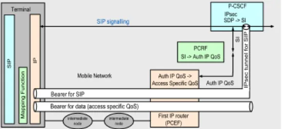
3) IMS: IMS (IP Multimedia Subsystem) [1] is defined within 3GPP as a service framework and as a mean for fixed and mobile network operators to provide the adequate QoS for transported services on the one hand, and perform a service-based differentiated charging on the other hand. IMS introduces independent network components based on SIP [8]; they are the Proxy Call Service Control function (P-CSCF), the Interrogating CSCF (I-CSCF), and the Serving CSCF (S-CSCF). The S-CSCF is located in the home network, it performs user authentication and implements the actual SIP registrar functionality and session control. The P-CSCF acts as a SIP proxy between the MN and the I-CSCF/S-CSCF and is located behind the first IP router of mobile networks. It stores for each terminal accounting and security association data. During IMS authentication procedure, the P-CSCF establishes an IPsec tunnel with the MN to provide integrity and ciphering for the transported SIP signaling. To ensure permanent MN reachability, this tunnel shall be maintained along the MN attachment period, imposing the need of an always-on IP connectivity in the mobile network. The P-CSCF also stores the Service Information (SI) deduced during session establishment. To enforce the QoS corresponding to SI on the mobile network, a new entity called PCRF (Policy and Charging Rules Function) has been introduced by the PCC architecture [9]. The P-CSCF sends SI to the PCRF. The PCRF deduces IP Authorized QoS and transfers it to the first IP router in the mobile network, called PCEF (Policy and Charging Enforcement Function). The PCEF deduces Access Specific QoS and ensures that the bearer established on the network level to handle the session traffic does not exceed this QoS. Figure 2 shows the number of contexts maintained in IMS and PCC architectures. Application of PCC architecture to SAE architecture is given in Figure 1. As the mobility protocol (e.g. PMIP) between the P-GW and the access gateways is not a bearer establishment protocol, new interfaces (see S7x in Figure 1) have been added by 3GPP between the PCRF and these gateways; increasing thus scalability risks. IMS and PCC architectures have other limitations regarding signaling cost and QoS management [10]. Indeed, PCC architecture role is limited to the enforcement of a given QoS on the mobile network independently of whether resources are available or
not. PCC entities could react to resource availability information in order to adapt the service accordingly; however as this information is distributed in all mobile network nodes reporting this information to PCC nodes could not be ensured
without consequent modifications on the specified
architectures. Terminal PCRF SIP signalling P-CSCF First IP router (PCEF) IP S IP M a p p in g F u n c ti o n I P s e c t u n n e l fo r S IP
Bearer for SIP
Bearer for data (access specific QoS)
Mobile Network S I Auth IP QoS SDP -> SI Auth IP QoS -> Access Specific QoS
SI -> Auth IP QoS IPsec intermediate node intermediate node
Figure 2. Contexts in IMS and PCC architectures nodes
4) Discussion on mobile networks and IMS scalability: The flattening approach appears to be a solution for the expected scalability risks; however the way it is applied for LTE/SAE and UMTS (HSPA+) does not solve all scalability issues. Even if these architectures remove some of the intermediate nodes, the first IP router is still centralised and manages a high number of users. As the PCRF and the P-CSCF entities are both located behind this first IP router they inherit the same kind of scalability issues. Duplicating the first IP routers, the P-CSCFs and the PCRFs can be envisaged when anticipating more and more subscribers in the future. However, as discussed in [11], load-aware algorithms for the selection of the less loaded node as well as a protocol to update the load of each node shall be deployed. Besides, distributing users on the different nodes can not be performed dynamically as these nodes cannot be changed during the lifetime of an established communication.
III. UFA ARCHITECTURE
An end-to-end architecture solution shall be defined to solve scalability issues. UFA has been proposed with this design objective. It distributes the first IP router, the PCRF and the P-CSCF functions in the BSs, now called UFA_GW. We choose to use SIP in the UFA_GW as the main protocol for UFA establishment and mobility procedures for the following reasons: 1) SIP is adopted in 3GPP for IMS 2) it can offer to operators the knowledge of the established applications 3) it is independent of the radio technology making UFA mobility procedures applicable to inter and intra technology HOs 4) it enables at the same time to establish sessions, manage their mobility and transport their related application description (SDP, Session Description Protocol [12]) . In the UFA_GW, the SIP layer acts as a B2BUA (Back-To-Back User Agent) in order to control SIP messages and perform their modification according to the operator policies. Thanks to this control and because the UFA_GWs simultaneously manage the SIP layer and all the network resource information, adapting applications to resource availability become possible. In this way, establishment/mobility procedure implicitly integrates QoS.
IV. UFA ESTABLISHMENT AND MOBILITY PROCEDURES When MN wants to initiate a service with a CN (Corresponding Node), it sends a SIP INVITE message to this CN to create a SIP session. The B2BUA in the Source UFA_GW (UFA_GW_S) stops this message and creates a second SIP INVITE message towards the CN. This induces the creation of two SIP sessions: one (MN–UFA_GW_S) between MN and UFA_GW_S and the other one (UFA_GW_S–CN) between UFA_GW_S and CN; each session is identified by a call ID. The B2BUA binds the two SIP sessions related to the established service. For a SIP message received from MN (resp. CN), From header, To header and MN (resp. CN) IP address in the SDP c field are copied in the corresponding SIP message sent to CN (resp. MN). Call ID is changed, MN (resp. CN) IP address in the contact header is replaced by UFA_GW_S IP address, and SDP content can be changed. Indeed, during service establishment, after the MN and the CN agree on a Requested SDP, the UFA_GW_S stores the Requested SDP and checks whether it can allocate the resources necessary to satisfy this SDP. If not it proposes another SDP Proposed SDP and sends it to MN and CN so that they begin their call with the corresponding application description, more details can be found in [10]. The Requested SDP can be later used by UFA_GW_S to propose a session upgrade when more resources become available.
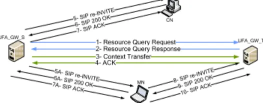
As shown in Figure 3, when a HO is anticipated by UFA_GW_S, (1) it sends to a set of candidate GWs a Resource Query Request that includes Requested SDP. (2) Each of these candidates answers according to its resources with a Proposed SDP. UFA_GW_S then selects a target UFA_GW (UFA_GW_T) and begins HO preparation. HO preparation aims at transferring the two SIP sessions (MN – UFA_GW_S) and (UFA_GW_S – CN) from UFA_GW_S to UFA_GW_T and pre-determining all the OSI layers configuration required for MN after its HO. The SIP REFER [13] method is not used as it cannot entirely answer to this objective; it is accompanied by the creation of new SIP sessions ((MN–UFA_GW_T) and (UFA_GW_T–CN)) which would necessitate a supplementary mechanism to bind these two new sessions. (3) Therefore, UFA_GW_S sends to UFA_GW_T Context Transfer message which includes both SIP sessions description (From, To, Contact, Requested SDP, MN capabilities, etc.). UFA_GW_T allocates an IP address for the MN (Add_IP_Addr), checks its uniqueness, confirms the Proposed SDP and (4) includes them with other UFA_GW_T related information in (ACK) message towards UFA_GW_S. (5, 5A) Based on the received message, UFA_GW_S builds two SIP re-INVITE messages to send to MN and CN.
CN
6- SIP 200 O
K
1- Resource Query Request 2- Resource Query Response 3- Context Transfer 4- ACK
MN
5A- SIP re-INVITE
8- SIP re-IN VITE UFA_GW_S UFA_GW_T 5- SIP re-INV ITE 6A- SIP 200 OK 9- SIP 200 OK 10- SIP AC K 7- SIP ACK
7A- SIP ACK
Figure 3.UFA handover procedure
A SIP re-INVITE message enables to update information related to an existing dialog (e.g. Contact header, SDP, c field of SDP). As (UFA_GW_S–CN) and (MN–UFA_GW_S) SIP sessions are transferred from UFA_GW_S to UFA_GW_T, SIP re-INVITE messages towards CN and MN have a contact header equal to UFA_GW_T IP address. They also include Proposed SDP; with a c field for the SIP re-INVITE message towards CN equal to the new IP address of MN after its HO (Add_IP_Addr). This indicates to CN to send data to this address. In order to provide better QoS and trigger the MN handover at L2 and L3 using the same messages, two new SIP headers are included in the SIP re-INVITE messages. The first SIP header is UFA_Appli_Config and is sent to CN and MN. As shown Table 1, it contains Add_IP_Addr and indicates to the application whether data bi-casting to/from the current MN IP address and Add_IP_Addr has to be performed during HO period so that data loss can be minimized. The second header is UFA_Terminal_Config and is only sent to MN to provide the
necessary inputs for L2 and L3 HOs execution.
UFA_Terminal_Config definition applies to the cases of mono
and multi-interfaced MN. As shown in Table 2Table 2, it
includes information about UFA_GW_T and indicates to MN
the interface (Interface_Name_Target) to attach to
UFA_GW_T for the session subject to HO and indicated by the SIP INVITE Call ID. It also indicates to MN whether the current IP address (Del_IP_Addr) of its current interface (Interface_Name_Source) shall continue to be attached to UFA_GW_S. In case of hard HO, Interface_Name_Target is equal to Interface_Name_Source. UFA_Terminal_Config concerns the MN network layer configuration; therefore it is duplicated in all SIP re-INVITE messages related to sessions subject to the same network handover (same UFA_GW_T).
Table 1. UFA_Appli_Config header
Add_IP_Addr The new address to be considered by the application for data transmission
Bi-cast=0 or 1 Indicates whether bi-casting shall be performed or not.
Table 2. UFA_Terminal_Config header
Interface_Name_Target The interface to be activated on the MN to
handle the session subject to handover. This interface will be attached to UFA_GW_T UFA_GW_T_MAC_Addr Used for L2 HO
UFA_GW_T_ESSID UFA_GW_T_Channel
UFA_GW_T_IP_Addr Used for IP HO
UFA_GW_T_Netmask Add_IP_Addr
Interface_Name_Source The current MN interface that handles the
session subject to handover Del_IP_Addr
0 or value
Specifies whether the current IP address (Del_IP_Addr) on the Interface_Name_Source has to be removed or not. If not it is equal to 0. In case of many MN ongoing sessions, sending multiple SIP re-INVITE messages may overload the radio interface. An alternative solution would be to include the information (UFA_Terminal_Config, UFA_Appli_Config, UFA_GW_T IP address, and Proposed SDP) related to all sessions subject to handover in a single SIP NOTIFY [14] message, supposing the MN has subscribed to a handover event. However this would require complex treatment in the terminal which has to extract the content of NOTIFY message and send internally a SIP re-INVITE message to the corresponding SIP UA (User Agent). A
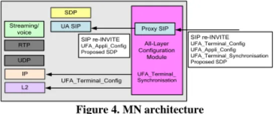
trade-off between radio load and terminal complexity shall be found. In our case, as shown in Figure 3, we choose to use SIP re-INVITE messages. When the terminal has many service sessions and in the usecases where UFA_Terminal_Config indicates that current IP address shall be deleted (for example the case of mono-interfaced terminal performing a hard HO) the application of the content of the first received SIP re-INVITE message will delete the current IP address and prevent from the reception of the other SIP re-INVITE messages related to the other sessions. To avoid this, we added a third SIP header called UFA_Terminal_Synchronisation that specifies to the terminal the number of SIP re-INVITE messages it has to wait for before executing UFA_Terminal_Config. To support HO, the terminal implements the architecture shown in Figure 4. An "All-Layer Configuration Module" intercepts SIP re-INVITE messages, extracts UFA_Terminal_Config and UFA_Terminal_Synchronisation and relays the SIP re-INVITE message to SIP UA. It then enforces L2 and L3 HOs according to UFA_Terminal_Synchronisation. UA SIP SDP Proxy SIP SIP re-INVITE UFA_Terminal_Config UFA_Appli_Config UFA_Terminal_Synchronisation Proposed SDP UFA_Terminal_Config Streaming/ voice RTP UDP All-Layer Configuration Module UFA_Terminal_ Synchronisation SIP re-INVITE UFA_Appli_Config Proposed SDP IP L2 Figure 4. MN architecture
To avoid packet loss during HO execution, UFA_GW_S can transfer packets received from CN to UFA_GW_T that buffers them. After HO, the MN sends a SIP re-INVITE message (8) to UFA_GW_T, which activates the MN context and begins data sending.
V. UFA PROOF OF CONCEPT AND PERFORMANCE RESULTS
To prove UFA concept and check the applicability of the above mobility procedure, we implemented UFA on a testbed. The testbed is given by the Figure 5. It consists of four computers. A desktop running Fedora Core 7 with kernel version 2.6.23 is used as UFA_CN. Two other desktops running Ubuntu 8.10 with kernel version 2.6.28.2 act as two UFA_GWs, they are equipped with 3com Wireless a/b/g PCi adapters. A laptop running Ubuntu 8.10 with kernel version 2.6.28.2 is the MN, it has a wireless Netgear a/b/g card. The testbed is based on IPv6.
UFA_GW_S UFA_GW_T MN 2001:2000:0:11::1/64 2001:2000:0:10::1/64 2001:2000:0:1::1 2001:2000:0:1::4/64 2001:2000:0:10:1:1:1:1 2001:2000:0:11:1:1:1:1 CN 2001:2000:0:1::2
Figure 5. UFA testbed
We implemented the B2BUA, the UFA_Terminal_Config and UFA_Appli_Config headers and all UFA HO messages excluding messages 1 and 2. Data transfer between the GWs and data buffering in the UFA_GW_T during HO are let for a further step of the testbed development. After session establishment, CN sends a streaming voice file to MN. We
evaluated UFA performance regarding messages lengths and
HO delays. The length of messages 5A, 6A, 7A, 5, 6, 7 are respectively 1229, 544, 494, 929, 535, 485 bytes. We considered the hard HO case as it is the most restricting one. The HO delay is measured at the application level (Appli_HO_Delay), it represents the delay between the last received data (D) packet before HO and the first received data packet after HO, its average value Appli_HO_Delay(UFA) on the testbed is 100ms. To show the relative gain of our solution, we implemented the classic SIP-based mobility scheme (reference case, (REF)) shown in Figure 6. The measured Appli_HO_Delay(REF) is 1258 ms in average for a configuration with 50ms-periodic Router Advertisements (RA) [15] and an activated Duplicate Address Detection (DAD) [15].
Appli_HO_Delay(REF) is 12 times larger than
Appli_HO_Delay(UFA). Figure 6 and Figure 7 show respectively the HO delay components for (REF) and (UFA) cases. Table 3 defines these components and gives their measured values. Appli_HO_Delay(REF) includes at least the delay components due to L2 and L3 HO and IP path update signaling. During tests, we observed for (REF) case that MN does not consider the first received RA, which explains the obtained 130 ms for D2 instead of 50 ms maximum.
@ 1 MN CN D1 D2 GW_T GW_S D (@ 2) R e-INV ITE Data is sent to GW_T Data is sent to GW_S D (@ 1) D (@ 1) at ta ch to G W _T Appli_HO_Delay D (@ 2) R A R A D et ac h fro m G W _S D(@ 1) D5 S IP d et ec t @ 2 IP c on fig D A D , N D D3 D4 R e-IN V ITE D(@ 1) O K OK ACK ACK @ 2 D (@ 1) D (@ 1) D (@ 1) D (@ 1) D (@ 1)
Figure 6. Reference (REF) case HO delays
D (@ 1) @ 1 MN CN D1 D3 @ 2 UFA_GW_T UFA_GW_S 5A -R e -INV ITE A7 -A C K 6A -OK D (@ 2) D (@ 2) D (@ 2 ) 6 -O K 5 -Re -I N V ITE 7 -AC K D (@ 2) D (@ 2)
Data is sent to UFA_GW_T Data is sent to UFA_GW_S
D (@ 1) D (@ 1 ) D (@ 1) D (@ 1 ) D (@ 1) a tt a c h t o G W _ T IP c o n fi g Appli_HO_Delay D (@ 2) D (@ 2) X p u t G W -M N D C N -G W D (@ 2 ) D (@ 2 ) D e ta c h f ro m G W _ S D (@ 1) D (@ 1) D (@ 1) D5 D G W -M N (X )
Figure 7. UFA HO delays
Comparing (UFA) and (REF) cases: D1 is the same for (UFA) and (REF); D2 in (UFA) does not exist since the MN address is proactively determined before HO execution order; D3 in (UFA) is very low given the fact that DAD has been performed proactively by UFA_GW_T and L2 and L3 configurations are simultaneously performed; D4 does not exit in (UFA) as SIP signaling is sent by UFA_GW_S. D5 is to due to SIP signaling delay; in (UFA) it corresponds to the time difference between the reception of message 7 on CN and the reception of message 7A on MN. Despite the very low-delay links considered for these measurements, D5 is not null for (REF). This is explained by the fact that when GW_T receives the OK message from CN towards MN, it needs to perform ND (Neighbor Discovery) [15] towards MN to determine its MAC address. This does not occur in (UFA) for first data received by the UFA_GW_T towards MN as we configured the UFA_GW_T neighbor table during the HO preparation phase. Note that Appli_HO_Delay(REF) and Appli_HO_Delay(UFA) are slightly different from (D1+D2+D3+D4+D5) and (D1+D3) respectively as voice packets are not sent continuously but spaced by 20 ms.
Table 3. Appli_HO_Delay components
Appli_HO_Delay components REF UFA
D1: the time necessary for MN to perform L2 HO (ms)
60 60
D2: the time necessary to receive Router
Advertisement (ms)
130 - D3: the time necessary for MN to be able to use
its interface at IP level, it is due to DAD procedure, interface configuration and ND (ms)
1000 20
D4: the time necessary for MN to detect IP HO
at SIP level and build the corresponding re-INVITE message (ms)
13 -
D5: the time necessary to exchange SIP signaling messages (SIP re-INVITE message, SIP OK, SIP ACK) (ms)
41 0
We also measured Appli_HO_Delay(UFA) for different
network configurations by varying DCN-GW and DGW-MN(X)
parameters. DCN-GW is the propagation delay on the CN-GW link. We assumed that packets on this link are only impacted
by this delay and not by the link throughput. DGW-MN(X) is the
transmission delay of a packet X over the MN-GW wireless link. It is due to the throughput XputGW-MN of this link. DCN-GW and XputGW-MN are varied on the testbed thanks to Linux tc qdisc commands. According to Figure 7, the content of SIP re-INVITE messages are considered by CN and MN only after the reception of message 7 (ACK) and 7A (ACK) respectively.
When (DGW-MN(5A+6A+7A) >> 3*DCN-GW), the CN may begin
data transmission towards Add_IP_Addr very earlier than the MN attachment to UFA_GW_T causing thus a considerable data loss. To optimize the solution performance, UFA_GW_S does not send ACK message (7) to CN before the reception of OK message (6A) from MN (see Figure 7), this reduces the time difference between message 7 and 7A reception on CN
and MN to │DGW-MN (7A) - DCN-GW│. When (D
GW-MN(5A+6A+7A) << 3*DCN-GW), to avoid losing the
connectivity with MN in hard HO situation, UFA_GW_S does
not delay the sending of message 7A to MN until the reception
oof message 6 from CN. Given these assumptions,
Appli_HO_Delay(UFA) can be calculated as follows:
If (2* DCN-GW <DGW-MN (5A+6A)) then
if (DCN-GW >DGW-MN (7A))
Delay=max[(D1+D3), (2*DCN-GW +DGW-MN (D)-DGW-MN (7A))]
if (DCN-GW < DGW-MN (7A))
Delay=max[((D1+D3)+DGW-MN (7A) -DCN-GW), (DGW-MN (7A)+DCN-GW )]
Else if (2* DCN-GW >DGW-MN (5A+ 6A))
Delay=max[(D1+D3),(4*DCN-GW+DGW-MN(D)-DGW-MN (5A+6A+7A))]
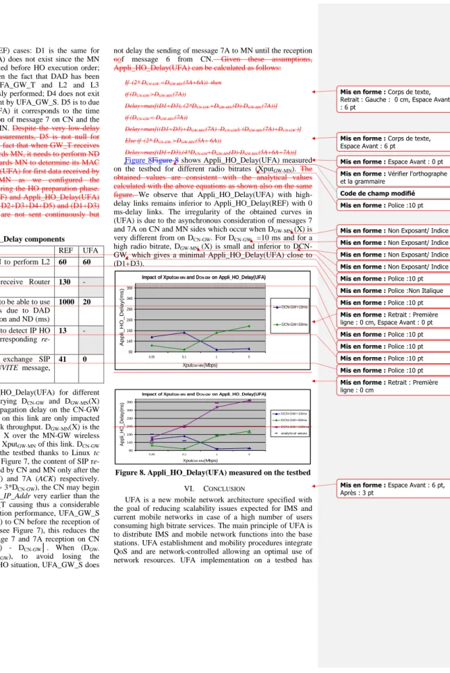
Figure 8Figure 8 shows Appli_HO_Delay(UFA) measured on the testbed for different radio bitrates (XputGW-MN). The
obtained values are consistent with the analytical values calculated with the above equations as shown also on the same figure. We observe that Appli_HO_Delay(UFA) with high-delay links remains inferior to Appli_HO_Delay(REF) with 0 ms-delay links. The irregularity of the obtained curves in (UFA) is due to the asynchronous consideration of messages 7
and 7A on CN and MN sides which occur when DGW-MN (X) is
very different from on DCN-GW. For DCN-GW =10 ms and for a
high radio bitrate, DGW-MN (X) is small and inferior to DCN-GW, which gives a minimal Appli_HO_Delay(UFA) close to (D1+D3).
Impact of XputGW-MN and DCN-GW on Appli_HO_Delay(UFA)
90 140 190 240 290 340 390 0,05 0,1 1 5 XputGW-MN(Mbps) A p p li _ H O _ D e la y (m s ) DCN-GW=10ms DCN-GW=50ms
Impact of XputGW-MN and DCN-GW on Appli_HO_Delay(UFA)
90 140 190 240 290 340 390 0,05 0,1 1 5 XputGW-MN(Mbps) A p p li_ H O _ D e la y( m s) DCN-GW=10ms DCN-GW=50ms DCN-GW=100ms analytical values
Figure 8. Appli_HO_Delay(UFA) measured on the testbed
VI. CONCLUSION
UFA is a new mobile network architecture specified with the goal of reducing scalability issues expected for IMS and current mobile networks in case of a high number of users consuming high bitrate services. The main principle of UFA is to distribute IMS and mobile network functions into the base stations. UFA establishment and mobility procedures integrate QoS and are network-controlled allowing an optimal use of network resources. UFA implementation on a testbed has
Mis en forme : Police :10 pt Mis en forme : Police :10 pt
Mis en forme : Police :10 pt Mis en forme : Police :10 pt Mis en forme : Police :10 pt Mis en forme : Police :10 pt Mis en forme : Corps de texte,
Retrait : Gauche : 0 cm, Espace Avant : 6 pt
Mis en forme : Corps de texte,
Espace Avant : 6 pt
Mis en forme : Espace Avant : 0 pt
Code de champ modifié Mis en forme : Vérifier l'orthographe
et la grammaire
Mis en forme : Police :10 pt Mis en forme : Non Exposant/ Indice Mis en forme : Non Exposant/ Indice Mis en forme : Non Exposant/ Indice Mis en forme : Non Exposant/ Indice Mis en forme : Police :Non Italique Mis en forme : Retrait : Première
ligne : 0 cm, Espace Avant : 0 pt
Mis en forme : Retrait : Première
ligne : 0 cm
Mis en forme : Espace Avant : 6 pt,
enabled the validation of its concept and allowed to measure the HO delay for different network delays. The minimum HO value is 100 ms for hard HO. This shows that UFA respects the requirements of the most restricting applications. Next work will also concern the interest of UFA and SIP use for non-SIP based applications.
NOTICE
UFA is being studied in P1857 Eurescom project and interests France Telecom, Portugal Telecom, Mobile Innovation Centre Hungary.
REFERENCES [1] 3GPP TS 23.228, "IP Multimedia Subsystem (IMS)".
[2] K. Daoud, P.Herbelin, Noel Crespi, "UFA: An Ultra Flat Architecture for High Bitrate Services in Mobile Networks", PIMRC 2008. [3] 3GPP TS 23.060, "GPRS Service description", release 9. [4] 3GPP TR 25.999, "High Speed Packet Access (HSPA) evolution" [5] 3GPP TS 23.402, "3GPP System Architecture Evolution: Architecture
Enhancements for non-3GPP accesses".
[6] 3GPP TS 36.300, "Evolved Universal Terrestrial Radio Access UTRA) and Evolved Universal Terrestrial Radio Access Network (E-UTRAN); Overall description".
[7] IETF RFC 5213: "Proxy Mobile IPv6". [8] IETF RFC 3261, " SIP: Session Initiation Protocol". [9] 3GPP TS 23.203, "Policy Control and Charging architecture". [10] K. Daoud, P.Herbelin, Noel Crespi, "One-Node Based Mobile
architecture for better QoS control", IFIP Wireless days 2008. [11] P. Agrawal, et.al, ”IP Multimedia Subsystems in 3GPP & 3GPP2:
Scalability issues”, IEEE Communications Magazine, January, 2008. [12] IETF RFC 2327, " SDP: Session Description Protocol ".
[13] IETF RFC 3515, " The Session Initiation Protocol (SIP) Refer Method". [14] IETF RFC 3265, "Session Initiation Protocol (SIP)-Specific Event
Notification"
[15] IETF RFC 2461, "Neighbor Discovery for IP Version 6 (IPv6)" .
Mis en forme : Espace Avant : 0 pt,
Après : 3 pt
Mis en forme : Retrait : Première
ligne : 0,38 cm, Espace Avant : 6 pt, Paragraphes solidaires, Lignes solidaires