HAL Id: hal-01931372
https://hal.archives-ouvertes.fr/hal-01931372
Submitted on 15 Jan 2019
HAL is a multi-disciplinary open access
archive for the deposit and dissemination of sci-entific research documents, whether they are pub-lished or not. The documents may come from teaching and research institutions in France or abroad, or from public or private research centers.
L’archive ouverte pluridisciplinaire HAL, est destinée au dépôt et à la diffusion de documents scientifiques de niveau recherche, publiés ou non, émanant des établissements d’enseignement et de recherche français ou étrangers, des laboratoires publics ou privés.
Rational Development of IT-SOFC Electrodes Based on
the Nanofunctionalization of La0.6Sr0.4Ga0.3Fe0.7O3
with Oxides. PART 1: Cathodes by Means of Iron Oxide
Andrea Bedon, Mathilde Rieu, Jean-Paul Viricelle, Antonella Glisenti
To cite this version:
Andrea Bedon, Mathilde Rieu, Jean-Paul Viricelle, Antonella Glisenti. Rational Development of IT-SOFC Electrodes Based on the Nanofunctionalization of La0.6Sr0.4Ga0.3Fe0.7O3 with Oxides. PART 1: Cathodes by Means of Iron Oxide. ACS Applied Energy Materials, ACS, 2018, 1 (12), pp.6840-6850. �10.1021/acsaem.8b01124�. �hal-01931372�
Rational Development of IT-SOFC Electrodes Based on
the Nanofunctionalisation of La
0.6Sr
0.4Ga
0.3Fe
0.7O
3with
Oxides. PART 1: Cathodes by Means of Iron Oxide
Andrea Bedon*†, Mathilde Rieu‡, Jean-Paul Viricelle‡, Antonella Glisenti†.† Department of Chemical Sciences, University of Padova, via F. Marzolo 1, 35131 Padova, Italy
‡ Mines Saint-Etienne, Univ Lyon, CNRS, UMR 5307 LGF, Centre SPIN, F - 42023 Saint-Etienne
France
ABSTRACT: Solid Oxide Fuel Cells (SOFCs) are electrochemical devices capable of converting and
stor-ing energy in a sustainable and efficient way. The decrease of the operatstor-ing temperature could be of great help for their diffusion. The use of nanocomposites is a smooth way to design materials with many advanced functionalities that could not be reached at the same time with only a single component. Our aim is in developing LSGF-based nanocomposites by depositing oxides’ nanoparticles in order to im-prove the electrocatalytic performances. In this first part we focussed on cathode and iron oxide was de-posited by wet impregnation. The composites’ powders have been extensively characterized by means of XRD, XPS, N2-asdorption, SEM, EDX, TPR, O2-TPD and the results compared with those obtained
for LSGF. The supporting perovskite stabilizes Fe(II) and a deep interaction between the deposited ox-ides and the perovskite surface is evident. Fe was observed to diffuse inside the perovskite during ther-mal treatments and this phenomenon greatly affects oxygen vacancies, mobility, and exchange capabil-ity. Focusing on the IT-SOFCs, symmetric cells of the type FeOx+LSGF/CGO/LSGF+FeOx have been
prepared starting from the nanocomposites’ powder. The effect of the SOFCs preparation conditions (temperature, atmosphere) on the electrode and on the cell has been assessed and compared, also through in-situ high temperature XRD, simulating, on the electrodes’ powder, the same treatment neces-sary to prepare the cell. The use of nanocomposites powders as starting point for electrodes allows to deeply modify the electrochemical performance. A thin, Sr/Fe-rich foil forms on the surface of the elec-trode during SOFC thermal treatment and deeply improves the electrochemical behaviour of the FeOx+LSGF cathode. The electrochemical results are encouraging for future application in SOFCs, as
nanocomposite has an ASR of 2.1 Ω·cm2 at 620°C, only ⅓ of LSGF’s one in the same conditions.
KEYWORDS: SOFC, cathode, perovskite, LSGF, wet impregnation, EIS, iron oxide.
INTRODUCTION
The increasingly high request of clean energy can benefit from Fuel Cells development and optimi-zation. Among these devices Solid Oxides Fuel Cells (SOFCs) are rapidly attracting interest due to their high efficiency and versatility in sustain-able energy conversion. The possibility to work also as electrolysers and to act as systems for chemical storage of energy and in Reversible mode1 are greatly relevant for sustainable and clean energy production, also because of the great impact on off-grid combinations. The hard demand on devices durability, the flexibility to operate also with carbon containing fuels are op-portunities that deserve appropriate answers. The development of specific materials is critical for these purposes. One of the drawbacks of SOFC is
the need of high operating temperature: Yttria Stabilized Zirconia based systems require tem-perature around 750-1000°C which results in high cost for material and plant, low stability and durability. Great improvement could be assured by the possibility to operate at lower temperature developing the so-called Intermediate Tempera-ture (IT)-SOFCs. IT-active electrodes economi-cally and environmentally sustainable need to be developed and optimized also from the durability point of view.
There is no clear distinction between IT-SOFC materials and conventional SOFC materials. Ma-terials used in IT-SOFCs can be seen as an evolu-tion of the ones used in convenevolu-tional cells, as they are able to speed up reactions with only lim-ited help from temperature. State-of-the-art
cath-2 ode materials are perovskite based2, and among
them cobalt based perovskites (LSCF3, BSCF4) have the best performances5. Currently, these ma-terials are being developed both in terms of com-position6,7 and morphology (to form nanostruc-tures)8 in order to further enhance performances. ASR of these materials varies depending on cell morphology and preparation/deposition proce-dure, as a rule of a thumb we can set to 1 Ω·cm2 at 600°C the limit for a suitable cathode material, measured on an electrolyte supported cell. This value has been chosen on the basis of the existing literature9,10.
In this work we decided to test nanocomposition as a mean to rationally design a new perovskite-based SOFC electrode materials with desired su-perior functionalities. Through nanocomposition, we modified LSGF (La0.6Sr0.4Ga0.3Fe0.7O3),
known for its stability and conductivity, to im-plement electrocatalytic activity while keeping its stability unaltered.
A perovskite is defined as a solid with ABX3
formula11: A and B are cations and X is an anion, most of the times oxygen, but in some case also a halogen 12. The great structural flexibility of this class of materials led to a great diversification of the applications5,13–16 and to the development of increasingly complex formulations. The accurate selection of the elements constituting the perov-skite can confer new properties to the material17, modify existing ones 18 or stabilize desired phas-es19. The perovskite La0.6Sr0.4Ga0.3Fe0.7O3
(LSGF) derives from simpler LaFeO3: the
addi-tion of Sr pushes Fe atoms to oxidaaddi-tion state 4+ and induces the formation of oxygen vacancies increasing electronic and ionic conductivity, whereas the presence of gallium leads to an ex-cellent stability, also towards reducing and chem-ically aggressive environments20,21. LSGF is al-ready known for its catalytic activity towards me-thane oxidation22 (this is a common feature among ferrites23,24) and it is studied as a material for dense ceramic membranes25,26. Application of LSGF as a SOFC cathode has been proposed, es-pecially coupled with LSGM as electrolyte27–29. In general LSGF more appreciated characteristics are: stability, reversibility under redox
environ-ments, high economic and environmental sus-tainability, while electrochemical performances need to be enhanced30.
Nanocomposition is attained with the deposition of iron oxide by wet impregnation on LSGF. The choice of non-noble, cheap impregnated phases is driven by the need of avoiding or limiting the use of expensive and/or critical elements (Critical Raw Materials, CRM)31. Beside economic rea-sons, Fe oxides are catalytically active in reduc-tion and have the ability to form different redox couples 32–34. At this purpose it has to be under-lined that particularly relevant can be the devel-opment of symmetric SOFCs to minimize the fabrication cost and maximize the durability of the device. To reach this goal we focus, in this contribution, on the cathode and work is in pro-gress to optimize a corresponding LSGF-based nanocomposite to be used as anode.
Impregnation35 is a process commonly used to enhance the performances of a material, and con-sists in depositing a new phase on an existing substrate from a solution. Often, the impregnated phase contains a noble metal, which is, usually, the real active phase while the substrate gives mainly mechanical strength; notable examples of this are Pt impregnated on carbon in Polymer Electrolyte Fuel Cells36 and in general automo-tive catalysts, on inert37–39 but also on active40 substrates. It is possible to distinguish between a wet and a dry impregnation41, whether the used precursors solution is in excess (wet) or has a limited volume corresponding to the porosity of the substrate (dry). Both wet and dry impregna-tion have been used in SOFC electrodes fabrica-tion. Wet impregnation has been employed to produce nanostructured electrodes inside a po-rous electrolyte scaffold42,43, but has received lit-tle attention compared to infiltration. With infil-tration processes, it is possible to prepare nanostructured electrodes or to deposit catalytic nanoparticles inside porous electrode backbones, and in both cases the performances of the materi-al are greatly enhanced44,45. Wet impregnation is performed on powders before electrode deposi-tion, while the infiltration is directly done on the deposited electrode. This means electrode
deposi-3 tion process, including firing at T>1000°C, has
an impact on the impregnated phase; such modi-fications are avoided in case of an infiltration. Wet impregnation has been chosen in this work because it allows to easily control the amount of deposited phase on powder substrates, aiming to exploit the electrode firing treatment to induce the formation of novel active structures arising from the interaction between a porous electrode and a deposited phase, not necessarily active by themselves. To the best of our knowledge, this kind of approach is unprecedented. In dry im-pregnation, in contrast, the amount of precursor deposited strictly depends on solubility making the quantitative control much more difficult. The impregnated LSGF + FeOx powders have
been studied by means of X-Ray Diffraction (XRD), Temperature Programmed Reduction (TPR), X-Ray Photoelectron Spectroscopy (XPS) and Energy Dispersive X-Ray Analysis (EDX). The surface modification subsequent to the oxide deposition has been studied also by means of N2
adsorption isotherms and SEM. The electro-chemical performances were evaluated by means of Electrochemical Impedance Spectroscopy (EIS), using the nanocomposite materials as SOFC cathodes in symmetrical electrolyte (CGO – cerium 90% gadolinium 10% mixed oxide) supported cells. CGO has been chosen to easily compare results with other devices’ performanc-es, considered the only limited literature available on LSGM. Since deposition of electrodes in-volves treatment at high temperatures potentially able to modify the LSGF composite, the powders (both LSGF and impregnated LSGF ones) have been treated under the same conditions and thor-oughly examined to monitor closely any modifi-cation of the material consequent to each prepara-tion step.
The electrochemical behaviour has been studied before and after a mild reducing treatment (20% CH4, 10% O2 at 600°C). To better understand the
observed differences, also the nanocomposite powders have been subjected to this treatment and their behaviour evaluated.
EXPERIMENTAL SECTION
Synthesis
Nanocomposite powder synthesis and treatment:
The supporting perovskite has been synthesized by means of a solid combustion synthesis route30. LSGF is, then, added to a solution of iron(II) ace-tate, and the mixture is kept under stirring for 24h; the amount of Fe(II) vs. supporting perov-skite was selected to obtain 10%mol deposition. The suspension is then mildly heated, avoiding boiling, until complete solvent evaporation; the resulting powder is treated at 550°C to remove the organic fraction. The powders were also treated at 1000 and 1100°C, the same tempera-tures used to prepare the SOFC.
SOFC cell preparation: Cells for EIS
measure-ments are electrolyte supported and prepared by screen printing the LSGF based material to be tested on both sides of a CGO pellet (diameter 20 mm, thickness 1.4 mm). The pellet was prepared by pressing the CGO powder (GDC10-TC, Fuel Cell Materials) and treating the so-obtained pellet at 1350°C for two hours. A perovskite ink was prepared by mixing LSGF powder with a fraction of CGO powder, and adding binder V400 (ESL, commercial) and solvent T404 (ESL, commer-cial) to adjust viscosity. The ink deposition is car-ried out by means of a screen printing machine. The layer is then dried in an oven at 100°C for 15 minutes. Two round layers with area 2.93cm2 on each side of the CGO pellets were printed this way. The symmetrical cell is treated at 1000°C and 1100°C to ensure a good electrical contact between the electrolyte and the electrodes. Treatments at temperatures lower than 1000°C have been found not to be sufficient to ensure enough mechanical stability to the electrodic lay-er. Finally, a gold grid is printed from a gold ink (8880-H, ESL, commercial) on both the elec-trodes, and the cell is treated a last time at 850°C for two hours.
Characterization
XRD. The XRD analyses at high temperature
were performed with a Bruker D8 Advance dif-fractometer with Bragg-Brentano geometry using a Cu Kα radiation (40 kV, 40 mA, λ = 0.154 nm)
4 equipped with a high temperature chamber
HTK16 (Anton Paar) and a scintillation detector preceded by a graphite monochromator. Working power is 1600W. The room temperature XRD analyses were performed with a Siemens D5000 diffractometer equipped with a rotating platinum sample holder and a scintillation detector preced-ed by a graphite monochromator. The data were collected at 0.03° in the (2θ) range from 10° to 70°. The crystalline phases were identified by the search-match method using the JCPDS database.
SEM. Field emission-scanning electron
micros-copy and EDX measures were carried on a Zeiss SUPRA 40VP. Morphological and EDX analyses were carried out setting the acceleration voltages at 20 kV.
TPR and O2-TPD. Temperature Programmed
Re-duction (TPR) and oxygen Temperature Pro-grammed Desorption (O2-TPD) were performed
with an Autochem II 2920 Micromeritics, equipped with a Thermal Conductivity Detector (TCD). The measurements were carried out in a quartz reactor by using 50 mg of sample and heating from RT to 900°C at 10°C min-1 under a 50 ml∙min-1 constant gas flow. Used gas mixture was H2 5% in Ar for TPR and Ar for O2-TPD.
TPR samples were previously outgassed with He (50 ml∙min-1) at room temperature. O2-TPD
sam-ples were previously fully oxidized at 900°C un-der pure O2 for 2 hours. Measured gas volumes
were determined calibrating the TCD with proper standards, and then converted to the molar amount reported in the Tables 2 and 3. An ESS Evolution mass quadrupole was used to check only oxygen was released during O2-TPD
meas-urements.
N2 adsorption isotherms. Isotherms were
meas-ured at 77K with a Micromeritics ASAP 2020 plus instrument. Superficial area by BET model and porosity by DFT calculations has been calcu-lated from adsorption curves.
XPS. The XPS measurements were carried out
with a Perkin Elmer Φ 5600ci Multi Technique System. The spectrometer was calibrated by as-suming the binding energy (BE) of the Au 4f7/2
line to be 84.0 eV with respect to the Fermi level. Both extended spectra (survey - 187.85 eV pass energy, 0.5 eV∙step-1, 0.05 s∙step-1) and detailed spectra (for La 3d, Fe 2p, Ga 2p, Sr 3d, O 1s and C 1s – 23.50 eV pass energy, 0.1 eV∙step-1, 0.1 s∙step-1) were collected with a standard Al Kα source working at 250 W. The standard deviation in the BE values of the XPS line is 0.10 eV. The atomic percentage, after a Shirley-type back-ground subtraction 46, was evaluated by using the
PHI sensitivity factors 47. The peak positions were corrected for the charging effects by con-sidering the C 1s peak at 285.0 eV and evaluating the BE differences 48.
EIS. Electrochemical Impedance Spectroscopy
(EIS) tests were performed on the following symmetrical cells: LSGF/CGO/LSGF and LSGF + FeOx/CGO/LSGF + FeOx. Impedance of the
cell was measured under air (normal operating condition for a double cell SOFC cathode); fur-thermore, cells after the first measurement were subjected to a mild reducing treatment under 20% CH4+10% O2 at 600°C for 1 hour, and then the
measurement was repeated to assess any varia-tion in activity. Data were collected with lartron 1286 Electrochemical Interface and So-lartron 1255 Frequency Response Analyzer de-vices. The applied excitation voltage is 10 mV.
RESULTS AND DISCUSSION
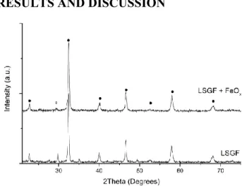
Figure 1. XRD pattern of LSGF and its
nano-composites. ●: LSGF, rhombohedral, JPCDS 04-016-7460; ○: LaSrGa3O7, melilite, tetragonal,
5
Room Temperature XRD
X-Ray Diffraction has been employed to careful-ly monitor any structural variation in samples be-fore, during and after all the treatments described in this work to prepare the symmetrical cells. XRD patterns of the impregnated powders have been compared with the one of the as-synthesized LSGF, in order to identify any new phase for-mation or modification. Before the deposition (Figure 1), LSGF shows the typical perovskitic pattern, and traces of a LaSrGa3O7 phase
impuri-ty (weak signal at 30° - some more information in Supporting Information) already observed in pre-vious works30. No pattern modification is ob-served after the deposition of iron oxide; in par-ticular no contributions of this oxide are evident. This can be due to the high dispersion or to the low amount of the deposited phases. Moreover, no shift is observed in the LSGF signals testify-ing that the deposited oxide is not diffused inside the perovskite cell during preparation. The only difference concerns the small signal at 30°, whose intensity strongly decreases after the dep-osition of the iron oxide, often completely disap-pearing.
XRD vs. temperature
A series of XRD measurements on nanocompo-site powders has been performed in situ during heating from 25°C to 1100°C to study any modi-fications undergone by the electrode powders while preparing the SOFC. In detail the following protocol was used: heating at 1000°C, cooling at RT, heating at 1100°C and finally cooling at RT. This choice is driven by the need to understand the differences in electrochemical behaviour ob-served in the SOFC when treating at 1000 and 1100°C. This protocol aims to identify any phase variation that could explain unexpected ASR (Area Specific Resistance) values measured by EIS (see paragraph EIS) after treating the cell at these temperatures.
In order to overcome the poor detectability of Fe oxide phases and to enable a more accurate study, the same test has been carried out on 10 and 30%
mol% composites, (prepared specifically for such XRD analyses).
6
Figure 2. XRD patterns of LSGF + FeOx. Left: treatment from 25°C (lowest pattern) to 1100°C and
cooling (highest pattern). Right: thermal treatment 25°C (lowest pattern) -1000°C-25°C-1100°C-25°C (highest pattern). ●: LSGF, rhombohedral, JPCDS 04-016-7460; ○: LaSrGa3O7, melilite, tetragonal,
JPCDS 00-045-0637; ◊: Pt (substrate), cubic, JPCDS 00-004-0802.
Measurements performed during in situ treat-ments remark the stability of the LSGF phase: no variation in its signals is detected during the whole process (Figure 2). During the first step heating (25 to 1000°C), the Fe composite is sub-jected only to a small increase of the signals of the LaSrGa3O7 secondary phase. Reflections of
deposited oxides are not observed due to their high dilution, so no information about them can be retrieved from XRD on 10% composites. Comparison between XRD patterns obtained dur-ing heatdur-ing to 1000°C, cooldur-ing and re-heatdur-ing at 1100°C (Figure 2) does not evidence any major differences, thus it can be assumed that no ob-servable phase variation happens between these temperatures, this is evidenced also by the direct comparison of the patterns reported in Supporting Information (Figure S1). Another interesting fea-ture is the stability of the LaSrGa3O7 reflection at
30°, that does not increase in intensity after the second treatment; this means it had already reached its equilibrium amount thus it is not ex-pected to further increase with aging. This is im-portant because it excludes a progressive increase of this secondary phase during operation, poten-tially harming integrity of the main LSGF phase. Iron composite pattern was unchanged from 10% to 30% samples. It has been decided not to fur-ther increase FeOx concentration until its
reflec-tion were visible because at too high concentra-tions the result could not be considered repre-sentative of the 10% composite, which is the aim of this study.
SEM on powders
Figure 3. SEM picture before and after
deposi-tion of iron oxide.
SEM images obtained before and after the depo-sition of the oxides do not show any difference (Figure 3).
7
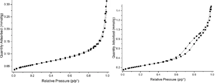
Figure 4. Left: N2 isotherm of LSGF. Right: N2 isotherm of LSGF + FeOx.
N2 isotherms
The comparison of the N2 isotherms of LSGF and
of the nano-composite (Figure 4) indicates a strong modification of the powders after the im-pregnation process, as expected in case of a good interaction between oxides and perovskitic sub-strate. Superficial area increases, from 4.4 m2/g of the pure perovskite, to 18.5 m2/g for the com-posite; also the shape of the isotherms differs suggesting a different morphology on the 10 nm scale. The LSGF perovskite shows a type II iso-therm, along with a very low specific surface ar-ea. The deposition of the oxide causes, beyond the increase in the specific surface area, a transi-tion of the isotherm towards type IV, that can be related to the formation of mesoporosities in which adsorbed N2 gas can condensate leading to
the typical hysteresis49.
The lack of appearance of new structures in SEM images and of XRD reflexes consequent to the iron oxide deposition, in addition to the effect on porosity, indicates that oxide nanoparticles are highly dispersed on the perovskite surface.
XPS, EDX characterization
Figure 5. XPS spectra of Fe2p peak of LSGF +
FeOx treated at different temperatures.
In Table 1 the atomic compositions obtained by XPS and EDX are summarized.
LSGF. The XPS atomic composition reveals Sr surface segregation. The comparison with the EDX atomic composition, which is more similar to the nominal one, confirms that the segregation is a superficial phenomenon. The thermal treat-ment causes the increasing diffusion of lantha-num toward the surface. The Fe/Ga atomic ratio is always near to the nominal one.
8
Table 1. XPS and EDX abundances
Sample La Sr Fe Ga O La /Sr (Fe+Ga) /La (Fe+Ga) /(La+Sr) Fe /Ga LSGF Nom. 12(30) 8(20) 14(35) 6(15) 60 1.5 1.7 1.0 2.3 XPS 4(15) 13(46) 8(28) 3(11) 71 0.3 2.5 0.6 2.6 EDX 13(31) 8(18) 15(36) 6(15) 58 1.7 1.6 1.0 2.4 Treat. 1000°C XPS 4(18) 11(47) 6(23) 3(12) 76 0.4 2.0 0.5 2.0 Treat. 1100°C XPS 6(24) 9(36) 7(28) 3(12) 75 0.7 1.6 0.7 2.3 LSGF+FeOx Nom. 12(29) 8(20) 15(37) 6(15) 60 1.5 1.8 1.1 2.5 XPS 8(29) 6(19) 13(46) 2(5) 72 1.5 1.8 1.1 8.7 EDX 13(32) 7(16) 16(40) 5(13) 60 2.0 1.6 1.1 3.2 Treat. 1000°C XPS 5(23) 7(33) 7(32) 2(12) 79 0.7 1.9 0.8 2.8 Treat. 1100°C XPS 4(18) 9(44) 6(29) 2(8) 80 0.4 2.0 0.6 3.7
Composition (at. %) of LSGF and LSGF + FeOx before and after 1000°C/1100°C treatments as measured by means of XPS and EDX. The nominal (Nom.) compositions are reported for comparison. The composition (at. %) considering only cations is inside brackets.
The comparison between the XPS and EDX compositions obtained for the perovskite and the nanocomposite, underline that the oxide phase is deposited on the surface of the perovskite and no significant diffusion inside the perovskite is ob-served in the as prepared composite. In fact, the Fe/Ga atomic ratio is higher than the nominal one (particularly for the surface-specific XPS results). The composite shows a more complex behaviour when heated at 1000°C or more: deposited cati-ons diffuse into the perovskite and their XPS concentration decrease. Iron depositions also af-fects A-site cations: lanthanum segregates to the surface and tends to replaces strontium, whereas in the composites these behaviours are switched. Focussing on the Fe 2p signal (Figure 5) it is pos-sible to observe the appearance of a shoulder around 709 eV, a binding energy value lower than the one corresponding to Fe(III) in perov-skite (710-710.5 eV). This confirms the presence of a FeO phase (as also outlined by TPR).
TPR
Figure 6 shows the TPR profile of the LSGF and LSGF + FeOx powders. Hydrogen consumptions
related to each peak are summarized in Table 2.
Focusing on the LSGF, the main item is the
Fe4+→Fe3+ reduction, between 300°C and 450°C23; above 800°C iron reduction to lower
oxidation states begins. As also reported in a pre-vious work, H2 consumption corresponds to a
Fe4+ abundance of 33% of all the iron atoms. This profile does not change with treatment at temperatures up to 1100°C (see Supporting In-formation S4), so modifications observed during measurements on impregnated oxides should be attributed to the presence of the supported oxide. The comparison among the TPR profiles of the nanocomposites and of the supporting LSGF, al-lows to go deeper into the interaction between supported oxide and supporting perovskite.
Table 2. Hydrogen consumption (mmole/mole) from TPR peaks Sample 400°C 500°C 800°C LSGF 115 0 0 Theoretical LSGF + 10% FeOx 115 0 100 LSGF + FeOx 120 0 110 LSGF + FeOx 1000°C 115 40 (1.5+19+19) 0 LSGF + FeOx 1100 °C 100 (30+70) 15 (1.5+7+7) Traces LSGF + FeOx 1000°C 10% O2 110 40 0
9
Hydrogen consumption for main peaks in Fig-ure 6 (mmol/mol of perovskite). Brackets indi-cate deconvolution of groups of peaks.
Concerning the profile of the as-prepared LSGF + FeOx the peak at 400°C is broadened with
re-spect to LSGF but the H2 consumption is very
similar. Literature data report that the reduction of bulk iron oxide by hydrogen usually proceeds through the following steps: Fe2O3 to Fe3O4 to
FeO to Fe, the reduction to metallic iron being complete below 1000°C 50-51. The peak at 800°C can, thus, be assigned to the Fe2+→Fe0 reduction of the deposited oxide, the area of this peak is consistent with this interpretation, being only slightly larger than the calculated one for this case.
The profile measured after the 1000°C treatment shows one main peak between 300°C and 450°C (Fe4+→Fe3+ atoms of the perovskite) and a group of three small peaks between 500°C and 750°C (area ratios 1:15:15, see arrows in Figure 6), whereas the peak at 800°C disappears. The dis-appearance of this signal suggests the inclusion of part of the deposited iron cations into the LSGF (the complete reduction of iron inside this perovskite, in fact, is observed at higher tempera-tures). XPS measurements indicates a significant segregation of Sr at the surface; this fact, together with the high concentration of iron on surface, could have induced the formation of a SrFeO3
-like phase (or similar) at the surface. SrFeO3 is
reported to be reduced completely between 400°C and 600°C with two non-resolved peaks52, similarly to the group of peaks observed at 500°C-700°C. In addition, SrFeO3 XRD
reflec-tions would be overlapped to LSGF’s ones and thus not distinguishable.
After the treatment at 1100°C a new small signal at 350° appears. The second and third peaks of the group between 500°C and 700°C lose more than half of their areas, but they keep the same 1:1 ratio: therefore, they can be attributed to the reduction of a same phase, that could be the SrFeO3-like one as previously proposed. Further
transformation of this phase, due to the relevant segregation of strontium at the surface, could be
at the origin of the 350°C peak phase. Some changes have been induced also on the perov-skite, because the Fe4+→Fe3+ peak area decreas-es. The differences in the TPR curve are not ob-served if the treatment at 1100°C is carried out with a controlled 10% O2 atmosphere (instead of
air), suggesting that the changes are caused by the oxidizing atmosphere at high temperature.
Figure 6. TPR profiles of LSGF + FeOx treated
at different temperatures. In red, the profile of LSGF before the deposition is shown for com-parison.
O2-TPD
Figure 7. O2 desorption of the tested samples.
O2-TPD is an effective tool to examine oxygen
exchange capability in ceramic materials. Results of O2-TPD measurements obtained after the
10 thermal treatment at 1000 and 1100°C for LSGF
and its nanocomposites are compared in Figure 7, and the amount of oxygen released is summa-rized in Table 3. The mass quadrupole indicated that oxygen was the only species in the carrier stream at the instrument outlet. All the curves show an oxygen release that begins at 200°C-250°C and does not end until 1000°C. Conven-tional separated α and β oxygen peaks (respec-tively, surface and lattice oxygen), cannot be dis-criminated, instead the two types of oxygen pro-duce two broad, not completely resolved signals. This behaviour is in accordance with other litera-ture data for (La,Sr) ferrites, which describe an uninterrupted release without any resolvable peak in the same range of temperatures53, and seems exclusive of this particular composition: different ferrites with elements such as Ni54, Bi53, Ca55, Ba56,57, Co58 or without La24 tend to desorb oxy-gen with more defined peaks. LaGaO3 has a
sin-gle small desorption signal peaked around 650°C59, so it appears that LSGF retains charac-teristics of ferrites rather than gallates. However, peaks tend to be shifted at higher temperatures probably for a stabilizing effect from gallium. Oxygen exchange properties of this material are attributed to the ability of B-site iron cation to easily shift between +3 and +4 oxidation states, and have been found to be related to the amount of Sr-doping and completely reversible60. As re-ported elsewhere55,61, the perovskite accommo-dates extra charge from the substitution of tri-valent La with bi-tri-valent Sr in three ways: oxida-tion of Fe3+ to Fe4+, hole formation or creation of oxygen vacancies. Both the Fe4+ and oxygen va-cancies formation are reported for Lax(Sr/Ca) 1-xFeO3 perovskites62.
Table 3. Amount per mole of desorbed oxygen during O2-TPD measurement (mmol/mol of perovskite).
900°C* 1000°C 1100°C
LSGF 52 48 46
LSGF+FeOx 41 42
*: 900°C is the calcination temperature of LSGF during its synthesis.
O2 TPD data seem to suggest that the profile is
the sum of two broad peaks, centred respectively around 400-500°C and 600-700°C. The thermal treatment at 1000°C has only little effect on pure LSGF.
After the treatment at 1100°C, in contrast, a sig-nificant decrease of the contribution at around 500°C and increase of the signal around 650°C, are observed. This behaviour can be related to the desorption of slightly bound surface active oxy-gen species (-oxygen) and the increment of ox-ygen vacancies, mobility and exchange capability (-oxygen desorption from lattice)24,63 favoured by temperature. The superficial LSGF -oxygen concentration, calculated considering experi-mental superficial area, is close to 1·1015 at-oms/cm2, compatible with an oxygen monolayer62. The FeOx deposition causes the
de-crease of both and -oxygen species; this de-crease can be also due to the surface covering after deposition. The increment of treatment tem-perature causes the increment of the contribution around 600-700°C, due to the lattice oxygen de-sorption, that get similar to the one of supporting LSGF; this behaviour can be related to the diffu-sion of the deposited Fe2+ inside the perovskite with the formation of mixed valence phases. It is possible to find some correlation between the results of these tests and the TPR ones and, in particular, with the TPR signals corresponding to the reduction Fe4+→Fe3+ (around 400-450°C): the variations of H2 consumption corresponding
to this process are consistent with the ones corre-sponding to O2 release. The interaction between
LSGF and the deposited phase induced small modifications in the perovskite, that, regarding TPR and O2-TPD measurements, can be
evaluat-ed in terms of ability to accommodate Fe4+ atoms and oxygen vacancies. Focusing on the amount of adsorbed/desorbed species (H2 during TPR
and O2 in O2-TPD) LSGF + FeOx shows a
behav-iour similar to the supporting LSGF. The for-mation of SrFeO3-type perovskitic phase
involv-ing the deposited specie, proposed in the previous paragraph, could explain why oxygen exchange properties are only little affected. More severe variations, in fact, were expected if deposited
11 iron oxide was incapable of this type of
interac-tion (so covering perovskite surface instead of forming a new phase).
SEM on cells
Images of sections of cells show the stability of the electrode morphology: in general, no substan-tial variation is observed after the thermal treat-ments, apart from a more compact arrangement of the particles (Figure 8 A and D, LSGF cell treated at 1000 and 1100°C, respectively). The electrode/electrolyte contact at the interface seems poor after a thermal treatment at 1000°C, although on a macroscopical scale no detachment was observed (even after the application of me-chanical stress - Figure 8 C, interface treated at 1000°C); the treatment at 1100°C induces a much better connection between the two layers (Figure 8 E). The electrode obtained after the deposition of Fe oxide followed by the same treatment at 1000°C is shown in Figure 8 F. The morphology, on a nanometres scale is maintained but on a mi-crometric scale the formation of some foils that wrap the LSGF particles is evident (Figure 8, compare G with B): on the left side of the picture a globular shape is visible, and the right half of the picture shows a tense foil, through which it is possible to observe the blurred shapes of the un-derlying perovskite particles. Their morphology can be better observed in Figure 8 K with higher magnification. None of these features were ob-served in simple LSGF electrodes. These struc-tures can be very thin; moreover, they improve the connection with the electrolyte (Figure 8 H), that appears better than in the case of the pure LSGF. This phase possibly is also responsible for the reductions at 600°C-700°C shown by TPR measurements. Treatment at 1100°C of the LSGF + FeOx electrolyte causes the collapse of these
foils; as a consequence, the surface of the parti-cles appears much rougher (Figure 8 I), probably because the surface is covered by the conglomer-ated fragments of the foils. During the 1100°C treatment, there is probably also a chemical deg-radation of the phase constituting the foils, that leads to the variations of the TPR profile de-scribed in the TPR paragraph. But the cause of the collapse is thermal rather than chemical: the
treatment under 10% O2 is able to maintain the
same exact TPR profile, so from a chemical point of view the sample has not been influenced. Nonetheless, the wrapping foil with any 1100°C treatment, even with controlled 10% O2
atmos-phere, is never observed (Figure 8 J).
EIS
Impedance measurements have been performed in air, to obtain information concerning the abil-ity of the material to exchange oxygen with the atmosphere and the electrolyte: the results ob-tained with this setup can be related, in general, to the behaviour as SOFC’s cathode. The Nyquist plots obtained by measurements in air (see Figure 9) have been fitted using a model circuit (Figure 9).
12 A B C D E F G H 2 µm 200 nm 200 nm 200 nm 2 µm 1 µm 1 µm
13
Figure 8. SEM images of sections of symmetrical cells on CGO. A and B: LSGF cell treated 1000°C,
electrode; C: LSGF cell treated at 1000°C, interface electrode/electrolyte; D: LSGF cell treated at 1100°C, electrode; E: LSGF cell treated at 1100°C, interface electrode/electrolyte; F and G: LSGF + FeOx cell treated at 1000°C, electrode, H: LSGF + FeOx cell treated at 1000°C, interface
elec-trode/electrolyte, I: LSGF + FeOx cell treated at 1100°C, electrode, J: LSGF + FeOx cell treated at
1100°C under 10% O2 atmosphere.
I J
200 nm 1 µm
14
Figure 9. A: Nyquist plot of LSGF 1100°C symmetrical cell at 620°C. B: Nyquist plot of LSGF + FeOx
cell treated at 1000°C, measured at 620°C. C: model circuit used for interpretation. LSGF cell: The plot has the shape of a
Warburg-like loop and a good fitting require to include three different elements: the ohmic resistance of the electrolyte (R1), a Warburg element (Ws1), related with oxygen diffusion, and a R//CPE ele-ment (R2 and CPE1), related to the polarization resistance of the air/perovskite interface during the uptake of atmospheric oxygen. The model circuit was chosen in accordance to Grunbaum’s work64 on perovskites, as we observe the same features that induced their choice to prefer fitting with a Warburg element instead of a Gerischer element; following the same interpretation, the R//CPE element represents dissociative adsorp-tion of oxygen, which is then the main contribu-tion to the polarizacontribu-tion resistance. ASR (Area Specific Resistance) is calculated as the sum of the resistances associated to R2 and Ws1. The
apex frequencies of the two observed processes are very similar, around 10-1 Hz, and the curves are almost overlapped. Because of this the uncer-tainty for the quantification of the two contribu-tions to overall resistance is high, and it is diffi-cult to monitor variations of each one of them. The performances of the tested materials are summarized in Figure 10, and have been
evaluat-ed on the basis of literature9,10. As pointed out in the introduction, at 600°C state-of-the-art materi-als have ASR below 1 Ω·cm2, so materials with similar performances can be considered suitable for application as electrodes. ·Compared with this ASR value, the LSGF perovskite has only modest conductivity: its ASR at 620°C is 7.3 Ω·cm2 after 1000°C treatment and 4.3 Ω·cm2 after 1100°C treatment. Performances of perovskites as elec-trode depend on the oxidation states of surface atoms65, so EIS tests have been repeated after a mild reducing treatment (600°C, CH4 20% O2
10%). The second measurement in air, after the reducing treatment, shows a small decrease of the resistance (10%) attributed to the reduction of Fe4+ in the crystalline lattice and to the creation of oxygen vacancies. The reducing treatment is also expected to reduce superficial sites so con-tributing to the resistance decrease. The capaci-tances associated with Ws1 and CPE1 are high:
Ws1 is around 10-1-100 F/cm2, and this is
con-sistent with bulk oxygen diffusion66; CPE1 is
close to 10-1 F/cm2. Capacitances of this size are chemical capacitances (involving a chemical re-action, as for example the oxidation/reduction of cations when O2- ions move).
A B
A
15
Figure 10. ASR measured at different temperatures for all the tested samples. Tag “red” designates
second measurements after methane reducing treatment.
Chemical capacitances are in general characteristic of a bulk limited process67, as in that case there is a clear influence of oxygen vacancies. This is normal for ionic conduction, but not expected for the dissociative oxygen adsorption and indicates oxygen vacancies are involved also in this process.
LSGF + FeOx cell: The perovskite impregnated
with iron shows the best performances (Figure 10), but only if treated at 1000°C. Performance after treatment at 1100°C is similar to simple LSGF. The cell treated at 1000°C requires only a Warburg element to fit the data. ASR is only 30% of the one of LSGF treated under the same conditions. After the mild reducing treatment the ASR is lowered, reaching 2.1 Ω·cm2 , a fair result considering the low temperature of 620°C and close to the 1 Ω·cm2 threshold. Capacitance is compatible with bulk limited diffusion, close to 1 F/cm2.
After the treatment at 1100°C the resistance is similar to the pure LSGF cell. For a pure LSGF cathode, higher temperature of firing meant lower
resistance due to better adhesion between LSGF particles and also between electrolyte and electrode. The possibility to obtain the same improvement also for LSGF + FeOx electrodes
and the cause of the increase of ASR of such electrodes treated at 1100°C have been investigated. TPR results showed that LSGF + FeOx powders do not retain the same curve after
treatments at 1000°C and 1100°C under air, but they do it if the 1100°C firing is carried out under controlled 10% O2 atmosphere. Therefore, a
LSGF + FeOx cell has been treated under the
same conditions (10% O2) to verify if the
changes in TPR profile were responsible for the loss of electrochemical activity. But, even in this case, the obtained ASR is similar with the LSGF + FeOx treated under air, so it can be concluded
that variations in TPRs were not linked with electrocatalytic activity. As already mentioned, no significant differences were observed in the XRD patterns.
The comparison of all data collected as a function of firing temperature, suggests that the explanation of the different performances of
16 LSGF + FeOx treated at 1000°C is
morphological. As evidenced by SEM measurements, this sample shows some thin foil wrapping perovskite particles. This foil collapses at 1100°C, even in controlled 10% O2
atmosphere. The formation of this layers is probably linked to the movement of iron atoms of the deposited oxide: note that in this sample the XPS iron concentration among only cations is 32%, instead of the 23% of pure LSGF at the same temperature (see Table 3). This difference is not observed in the same sample treated at 1100°C, and indicates the prevalence of iron atoms at the surface. Experimental data show the disappearance of polarization resistance, in fact ASR of LSGF + FeOx cell corresponds to
Warburg resistance of the same cell with only LSGF (see Supporting Information Table S1). It can be deduced that the obtained foil structure is able to assist the dissociative adsorption of oxygen molecules. Such a structure could easily provide a number of new iron sites, some fitting for the interaction with oxygen, and this explains why polarization resistance decreases. It is not easy, however, to define exactly what the observed structure exactly is. Some combined data from XRD and TPR suggested the formation of a SrFeO3-like phase, which has some
interesting properties for this application52,68, but, as a perovskite, it does not usually form such extended foil structures.
CONCLUSIONS
In this contribution, we successfully obtained a material with increased electrochemical activity, while keeping unaltered the LSGF backbone that assures the high stability of the electrode. The deposition of iron oxide significantly decreases the ASR and the reasons have been examined and explained.
It has been demonstrated that deposition of a proper oxide and subsequent temperature treat-ment can modify superficial segregation of se-lected elements: iron wet impregnation heavily influenced La/Sr ratio. The surface segregation of Sr in the LSGF + FeOx nanocomposite has strong
consequence on properties allowing the
for-mation of a perovskite layer of the type SrFeO3.
The consequences of these interactions have been studied in depth and have been related with oxy-gen mobility and catalytic and electrocatalytic activities.
The importance of Fe species for the functionali-ty of ferrites is highlighted. Redox couple Fe4+ and Fe3+ has proven to be fundamental in oxygen mobility, and the ability of the material to form Fe4+ centres has been related to the formation of oxygen vacancies and ionic conduction, in ac-cordance with existing literature. Fe sites have also been proven to be fundamental during elec-trocatalysis: polarization resistance has been found to increase/decrease depending on their superficial concentration. During impedance analysis, an ambiguous response of impedance with anomalously high capacitance has been identified, but no clear explanation was found. A significant improvement of electrochemical performances has been observed for LSGF + FeOx materials treated at 1000°C: the Area
Spe-cific Resistance decreasing at the 30% of initial value. The origin of this improvement has been examined and related to the formation of thin foils that act as a connection between particles. These structures have been found to collapse with treatments at temperatures above 1000°C. The good results found with these materials suggest their application as SOFC electrode should be taken in consideration, as their chemical stability is superior to common state-of-the-art cathode materials.
ASSOCIATED CONTENT
Supporting Information. XRD study on LSGF
+ FeOx composites including LaSrGa3O7
disap-pearance, repeatability of TPR results on LSGF with varying treatment temperature, comparison between Ws1 resistance and ASR respectively of LSGF and LSGF + FeOx. This material is
availa-ble free of charge via the Internet at http://pubs.acs.org.
AUTHOR INFORMATION
17 * Andrea Bedon. E-mail:
andrea.bedon@unipd.it, andrebed@outlook.it.
ACKNOWLEDGMENT
A. Bedon and A. Glisenti have received funding from the European Union's H2020 Programme under grant agreement 686086 PARTIAL-PGMs. REFERENCES
(1) Wendel, C. H.; Kazempoor, P.; Braun, R. J. Novel Electrical Energy Storage System Based on Reversible Solid Oxide Cells: System Design and Operating Conditions. J. Power
Sources 2015, 276, 133–144.
(2) Sun, C.; Hui, R.; Roller, J. Cathode Materials for Solid Oxide Fuel Cells: A Review. J. Solid State Electrochem. 2010, 14, 1125–1144.
(3) Perz, M.; Bucher, E.; Gspan, C.; Waldhäusl, J.; Hofer, F.; Sitte, W. Long-Term Degradation of La 0.6 Sr 0.4 Co 0.2 Fe 0.8 O 3-δ IT-SOFC Cathodes Due to Silicon Poisoning. Solid
State Ionics 2016, 288, 22–27.
(4) Setevich, C.; Prado, F.; Caneiro, A. Electrochemical Response of Several Cathode Configurations Prepared with Ba0.5Sr0.5Co0.8Fe0.2O3-δ and Ce0.9Gd0.1O1.95 for IT-SOFC. J. Solid State Electrochem. 2016, 20, 1633–1643. (5) Jun, A.; Kim, J.; Shin, J.; Kim, G. Perovskite as a Cathode
Material: A Review of Its Role in Solid-Oxide Fuel Cell Technology. ChemElectroChem 2016, 3, 511–530.
(6) Choi, S.; Yoo, S.; Kim, J.; Park, S.; Jun, A.; Sengodan, S.; Kim, J.; Shin, J.; Jeong, H. Y.; Choi, Y.; Kim, G.; Liu, M. Highly Efficient and Robust Cathode Materials for Low-Temperature Solid Oxide Fuel Cells: PrBa0.5Sr0.5Co(2-x)Fe(x)O(5+δ). Sci. Rep. 2013, 3, 2426.
(7) Xia, L.-N.; He, Z.-P.; Huang, X. W.; Yu, Y. Synthesis and Properties of SmBaCo 2−x Ni x O 5+δ Perovskite Oxide for IT-SOFC Cathodes. Ceram. Int. 2016, 42, 1272–1280. (8) Mogni, L. V.; Yakal-Kremski, K.; Chanquia, C. M.; Gao, Z.;
Wang, H.; Caneiro, A.; Barnett, S. A. Study of Electrode Performance for Nanosized La0.4Sr0.6Co0.8Fe0.2O3-I" IT-SOFC Cathode. ECS Trans. 2015, 66, 169–176.
(9) Philippeau, B.; Mauvy, F.; Mazataud, C.; Fourcade, S.; Grenier, J.-C. Comparative Study of Electrochemical Properties of Mixed Conducting Ln2NiO4+δ (Ln=La, Pr and Nd) and La0.6Sr0.4Fe0.8Co0.2O3−δ as SOFC Cathodes Associated to Ce0.9Gd0.1O2−δ, La0.8Sr0.2Ga0.8Mg0.2O3−δ and La9Sr1Si6O26.5 Electrolytes. Solid State Ionics 2013,
249–250, 17–25.
(10) Rembelski, D.; Viricelle, J. P.; Combemale, L.; Rieu, M. Characterization and Comparison of Different Cathode Materials for SC-SOFC: LSM, BSCF, SSC, and LSCF. Fuel
Cells 2012, 12, 256–264.
(11) Johnsson, M.; Lemmens, P. Crystallography and Chemistry of Perovskites. In Handbook of Magnetism and Advanced
Magnetic Materials; John Wiley & Sons, Ltd: Chichester,
UK, 2007; p 11.
(12) Saparov, B.; Mitzi, D. B. Organic–Inorganic Perovskites: Structural Versatility for Functional Materials Design.
Chem. Rev. 2016, 116, 4558–4596.
(13) Uchino, K. Glory of Piezoelectric Perovskites. Sci. Technol.
Adv. Mater. 2015, 16, 046001.
(14) Kozuka, H.; Ohbayashi, K.; Koumoto, K. Electronic Conduction in La-Based Perovskite-Type Oxides. Sci.
Technol. Adv. Mater. 2015, 16, 026001.
(15) Labhasetwar, N.; Saravanan, G.; Kumar Megarajan, S.; Manwar, N.; Khobragade, R.; Doggali, P.; Grasset, F. Perovskite-Type Catalytic Materials for Environmental Applications. Sci. Technol. Adv. Mater. 2015, 16, 036002. (16) Sunarso, J.; Baumann, S.; Serra, J. M.; Meulenberg, W. A.;
Liu, S.; Lin, Y. S.; Diniz da Costa, J. C. Mixed Ionic– electronic Conducting (MIEC) Ceramic-Based Membranes for Oxygen Separation. J. Memb. Sci. 2008, 320 13–41. (17) Echeverri, E.; Arnache, O. Structural and Impedance
Analysis of Co-Doped SrTiO3 Perovskite. J. Phys. Conf. Ser.
2016, 687, 012040.
(18) Aguadero, A.; Pérez-Coll, D.; Alonso, J. A.; Skinner, S. J.; Kilner, J. A New Family of Mo-Doped SrCoO 3−δ Perovskites for Application in Reversible Solid State Electrochemical Cells. Chem. Mater. 2012, 24, 2655–2663. (19) Zeng, P.; Ran, R.; Chen, Z.; Zhou, W.; Gu, H.; Shao, Z.; Liu,
S. Efficient Stabilization of Cubic Perovskite SrCoO3−δ by B-Site Low Concentration Scandium Doping Combined with Sol–gel Synthesis. J. Alloys Compd. 2008, 455, 465–470. (20) Vivet, a.; Geffroy, P. M.; Chartier, T.; Del Gallo, P.; Richet, N. La(1−x)SrxFe(1−y)GayO3−δ Perovskite Membrane: Oxygen Semi-Permeation, Thermal Expansion Coefficient and Chemical Stability under Reducing Conditions. J.
Memb. Sci. 2011, 372, 373–379.
(21) Juste, E.; Julian, A.; Etchegoyen, G.; Geffroy, P.; Chartier, T.; Richet, N.; Delgallo, P. Oxygen Permeation, Thermal and Chemical Expansion of (La, Sr)(Fe, Ga)O3−δ Perovskite Membranes. J. Memb. Sci. 2008, 319, 185–191.
(22) Tian, T.; Zhan, M.; Wang, W.; Chen, C. Surface Properties and Catalytic Performance in Methane Combustion of La0.7Sr0.3Fe1−yGayO3−δ Perovskite-Type Oxides. Catal.
Commun. 2009, 10, 513–517.
(23) Isupova, L. A.; Yakovleva, I. S.; Alikina, G. M.; Rogov, V. A.; Sadykov, V. A. Reactivity of La1 − x Sr x FeO3 − y (x = 0–1) Perovskites in Oxidation Reactions. Kinet. Catal. 2005, 46, 729–735.
(24) Falcón, H.; Barbero, J. A.; Alonso, J. A.; Martínez-Lope, M. J.; Fierro, J. L. G. SrFeO 3 - δ Perovskite Oxides: Chemical Features and Performance for Methane Combustion. Chem.
Mater. 2002, 14, 2325–2333.
(25) Geffroy, P.-M.; Fouletier, J.; Richet, N.; Chartier, T. Rational Selection of MIEC Materials in Energy Production Processes. Chem. Eng. Sci. 2013, 87, 408–433.
18
and Ga Doped LaFeO3. Solid State Ionics 1999, 122, 113–121. (27) Fu, Q.; Xu, X.; Peng, D.; Liu, X.; Meng, G. Preparation and
Electrochemical Characterization of Sr- and Mn-Doped LaGaO3 as Anode Materials for LSGM-Based SOFCs. J.
Mater. Sci. 2003, 38, 2901–2906.
(28) Koutcheiko, S.; Whitfield, P.; Davidson, I. Electrical and Thermal Properties of La0.7Sr0.3Ga0.6Fe0.4O3 Ceramics.
Ceram. Int. 2006, 32, 339–344.
(29) Shkerin, S. N.; Kyz’min, A. V.; Gyrdasova, O. I.; Stroeva, A. Y.; Nikonov, A. V. Electrical Conductivity and Thermal Expansion of La1 – x Sr x Fe1 – y Ga y O3 – δ (x = 0.2–0.5; y = 0–0.4). Russ. J. Electrochem. 2017, 53, 154–160.
(30) Bedon, A.; Natile, M. M.; Glisenti, A. On the Synthesis and Stability of La0.6Sr0.4Ga0.3Fe0.7O3. J. Eur. Ceram. Soc.
2017, 37, 1049–1058.
(31) European Commission. On the Review of the List of Critical
Raw Materials for the EU and the Implementation of the Raw Materials Initiative; 2014.
(32) Xu, P.; Zeng, G. M.; Huang, D. L.; Feng, C. L.; Hu, S.; Zhao, M. H.; Lai, C.; Wei, Z.; Huang, C.; Xie, G. X.; Liu, Z. F. Use of Iron Oxide Nanomaterials in Wastewater Treatment: A Review. Sci. Total Environ. 2012, 424, 1–10.
(33) Rahim Pouran, S.; Abdul Raman, A. A.; Wan Daud, W. M. A. Review on the Application of Modified Iron Oxides as Heterogeneous Catalysts in Fenton Reactions. J. Clean.
Prod. 2014, 64, 24–35.
(34) Lin, S.-S.; Gurol, M. D. Catalytic Decomposition of Hydrogen Peroxide on Iron Oxide: Kinetics, Mechanism, and Implications. Environ. Sci. Technol. 1998, 32, 1417–1423. (35) Schwarz, J. A.; Contescu, C.; Contescu, A. Methods for
Preparation of Catalytic Materials. Chem. Rev. 1995, 95, 477–510.
(36) Mehta, V.; Cooper, J. S. Review and Analysis of PEM Fuel Cell Design and Manufacturing. J. Power Sources 2003, 114, 32–53.
(37) Shelef, M.; McCabe, R. . Twenty-Five Years after Introduction of Automotive Catalysts: What Next? Catal.
Today 2000, 62, 35–50.
(38) Gandhi, H. S.; Graham, G. W.; McCabe, R. W. Automotive Exhaust Catalysis. J. Catal. 2003, 216, 433–442.
(39) Glisenti, A.; Pacella, M.; Guiotto, M.; Natile, M. M.; Canu, P. Largely Cu-Doped LaCo 1−x Cu x O 3 Perovskites for TWC: Toward New PGM-Free Catalysts. Appl. Catal. B Environ.
2016, 180, 94–105.
(40) Keav, S.; Matam, S.; Ferri, D.; Weidenkaff, A. Structured Perovskite-Based Catalysts and Their Application as Three-Way Catalytic Converters—A Review. Catalysts 2014, 4, 226–255.
(41) Munnik, P.; De Jongh, P. E.; De Jong, K. P. Recent Developments in the Synthesis of Supported Catalysts.
Chem. Rev. 2015, 115, 6687–6718.
(42) Jiang, S. P. A Review of Wet Impregnation - An Alternative
Method for the Fabrication of High Performance and Nano-Structured Electrodes of Solid Oxide Fuel Cells. Mater. Sci.
Eng. A 2006, 418, 199–210.
(43) Chen, J.; Liang, F.; Liu, L.; Jiang, S.; Chi, B.; Pu, J.; Li, J. Nano-Structured (La, Sr)(Co, Fe)O3+YSZ Composite Cathodes for Intermediate Temperature Solid Oxide Fuel Cells. J. Power Sources 2008, 183, 586–589.
(44) Jiang, Z.; Xia, C.; Chen, F. Nano-Structured Composite Cathodes for Intermediate-Temperature Solid Oxide Fuel Cells via an Infiltration/Impregnation Technique.
Electrochim. Acta 2010, 55, 3595–3605.
(45) Ding, D.; Li, X.; Lai, S. Y.; Gerdes, K.; Liu, M. Enhancing SOFC Cathode Performance by Surface Modification through Infiltration. Energy Environ. Sci. 2014, 7, 552. (46) Shirley, D. A. High-Resolution x-Ray Photoemission
Spectrum of the Valence Bands of Gold. Phys. Rev. B 1972, 5, 4709–4714.
(47) Briggs, D. Handbook of X-Ray Photoelectron Spectroscopy C. D. Wanger, W. M. Riggs, L. E. Davis, J. F. Moulder and G. E.Muilenberg Perkin-Elmer Corp., Physical Electronics Division, Eden Prairie, Minnesota, USA, 1979. 190 Pp. $195.
Surf. Interface Anal. 1981, 3, v–v.
(48) McIntyre, N. S.; in D. Briggs and M. P. Seah (eds.). Practical Surface Analysis in Auger and X-Ray Photoelectron Spectroscopy. John Wiley Sons, New York 1983, 1, 397–427. (49) Gregg S J; Sing, K. S. W. Adsorption, Surface Area and
Porosity. New York, Academic Press. 1999.
(50) Requies, J.; Güemez, M. B.; Perez Gil, S.; Barrio, V. L.; Cambra, J. F.; Izquierdo, U.; Arias, P. L. Natural and Synthetic Iron Oxides for Hydrogen Storage and Purification. J. Mater. Sci. 2013, 48, 4813–4822.
(51) Lin, H.-Y.; Chen, Y.-W.; Li, C. The Mechanism of Reduction of Iron Oxide by Hydrogen. Thermochim. Acta 2003, 400, 61–67.
(52) Xiao, G.; Liu, Q.; Wang, S.; Komvokis, V. G.; Amiridis, M. D.; Heyden, A.; Ma, S.; Chen, F. Synthesis and Characterization of Mo-Doped SrFeO 3-δ as Cathode Materials for Solid Oxide Fuel Cells. J. Power Sources 2012,
202, 63–69.
(53) Niu, Y.; Sunarso, J.; Liang, F.; Zhou, W.; Zhu, Z.; Shao, Z. A Comparative Study of Oxygen Reduction Reaction on Bi- and La-Doped SrFeO3 − δ Perovskite Cathodes. J.
Electrochem. Soc. 2011, 158, B132–B138.
(54) Chen, S. Q.; Wang, H.; Liu, Y. Perovskite La-St-Fe-O (St=Ca, Sr) Supported Nickel Catalysts for Steam Reforming of Ethanol: The Effect of the A Site Substitution. Int. J.
Hydrogen Energy 2009, 34, 7995–8005.
(55) Pecchi, G.; Jiliberto, M. G.; Buljan, A.; Delgado, E. J. Relation between Defects and Catalytic Activity of Calcium Doped LaFeO 3 Perovskite. Solid State Ionics 2011, 187, 27– 32.
(56) Xian, H.; Li, F.-L.; Li, X.-G.; Zhang, X.-W.; Meng, M.; Zhang, T.-Y.; Tsubaki, N. Influence of Preparation Conditions to Structure Property, NOx and SO2 Sorption Behavior of the
19
BaFeO3−x Perovskite Catalyst. Fuel Process. Technol. 2011,
92, 1718–1724.
(57) Dong, F.; Chen, D.; Chen, Y.; Zhao, Q.; Shao, Z. La-Doped BaFeO3-δ Perovskite as a Cobalt-Free Oxygen Reduction Electrode for Solid Oxide Fuel Cells with Oxygen-Ion Conducting Electrolyte. J. Mater. Chem. 2012, 22, 15071– 15079.
(58) Li, N.; Boréave, A.; Deloume, J. P.; Gaillard, F. Catalytic Combustion of Toluene over a Sr and Fe Substituted LaCoO3 Perovskite. Solid State Ionics 2008, 179, 1396–1400. (59) Zhang, R.; Villanueva, A.; Alamdari, H.; Kaliaguine, S.
Crystal Structure, Redox Properties and Catalytic Performance of Ga-Based Mixed Oxides for NO Reduction by C3H6. Catal. Commun. 2008, 9, 111–116.
(60) Leontiou, A. A.; Ladavos, A. K.; Bakas, T. V.; Vaimakis, T. C.; Pomonis, P. J. Reverse Uptake of Oxygen from La1−xSrx (Fe3+/Fe4+)O3±δ Perovskite-Type Mixed Oxides (x = 0.00, 0.15, 0.30, 0.40, 0.60, 0.70, 0.80, 0.90). Appl. Catal. A Gen.
2003, 241, 143–154.
(61) Seiyama, T.; Yamazoe, N.; Eguchi, K. Characterization and Activity of Some Mixed Metal Oxide Catalysts. Ind. Eng.
Chem. Prod. Res. Dev. 1985, 24, 19–27.
(62) Nitadori, T.; Misono, M. Catalytic Properties of La1 − XA′xFeO3(A′ = Sr,Ce) and La1 − XCexCoO3. J. Catal. 1985, 93,
459–466.
(63) Barbero, B. P.; Gamboa, J. A.; Cadús, L. E. Synthesis and Characterisation of La1−xCaxFeO3 Perovskite-Type Oxide Catalysts for Total Oxidation of Volatile Organic Compounds. Appl. Catal. B Environ. 2006, 65, 21–30. (64) Grunbaum, N.; Dessemond, L.; Fouletier, J.; Prado, F.;
Mogni, L.; Caneiro, A. Rate Limiting Steps of the Porous La0.6Sr0.4Co0.8Fe0.2O3−δ Electrode Material. Solid State
Ionics 2009, 180, 1448–1452.
(65) Jiang, S. Origin of the Initial Polarization Behavior of Sr-Doped LaMnO3 for O2 Reduction in Solid Oxide Fuel Cells.
Solid State Ionics 2001, 138, 183–190.
(66) Baumann, F. S.; Maier, J.; Fleig, J. The Polarization Resistance of Mixed Conducting SOFC Cathodes: A Comparative Study Using Thin Film Model Electrodes.
Solid State Ionics 2008, 179, 1198–1204.
(67) Adler, S. B. Factors Governing Oxygen Reduction in Solid Oxide Fuel Cell Cathodes. Chem. Rev. Rev. 2004, 104, 4791– 4843.
(68) Porras-Vazquez, J. M.; Smith, R. I.; Slater, P. R. Investigation into the Effect of Si Doping on the Cell Symmetry and Performance of Sr1-YCayFeO3- SOFC Cathode Materials. J. Solid State Chem. 2014, 213, 132–137.