Voltage rectification effects in mesoscopic superconducting triangles: Experiment and modeling
N. Schildermans,1A. B. Kolton,2R. Salenbien,1 V. I. Marconi,2A. V. Silhanek,1and V. V. Moshchalkov11INPAC-Institute for Nanoscale Physics and Chemistry, Nanoscale Superconductivity and Magnetism and Pulsed Fields Group,
K. U. Leuven, Celestijnenlaan 200D, B-3001 Leuven, Belgium
2Departamento de Física Atómica, Molecular y Nuclear, Universidad Complutense de Madrid, 28040 Madrid, Spain
共Received 26 July 2007; published 3 December 2007兲
The interaction of externally applied currents with persistent currents induced by magnetic field in a meso-scopic triangle is investigated. As a consequence of the superposition of these currents, clear voltage rectifi-cation effects are observed. We demonstrate that the amplitude of the rectified signal strongly depends on the configurations of the current leads with the lowest signal obtained when the contacts are aligned along a median of the triangle. When the contacts are aligned off centered compared to the geometrical center, the voltage response shows oscillations as a function of the applied field, whose sign can be controlled by shifting the contacts. These results are in full agreement with theoretical predictions for an analogous system consisting of a closed loop with a finite number of identical Josephson junctions.
DOI:10.1103/PhysRevB.76.224501 PACS number共s兲: 74.25.Fy, 74.25.Sv, 74.78.Na, 73.40.Ei
In the past few years considerable attention has been paid to the mechanisms responsible for the ratchet effects in a broad variety of physical systems such as colloids,1granular materials,2fluids,3atoms in optical traps,4electrons in semi-conductor heterostructures,5and Josephson systems.6–8In all cases, a net flux of particles driven by a zero average alter-nating excitation results from the interaction of the media with an asymmetric potential. This behavior has also been theoretically predicted and experimentally corroborated for the motion of quantum flux lines in superconducting samples with a pinning landscape lacking inversion symmetry.9–15In superconducting systems, this effect manifests itself as a nonzero dc voltage even when an ac excitation is sent through the superconductor, thus acting as a rectified voltage. Interestingly, it has been recently demonstrated that the pres-ence of this voltage rectification in a superconductor does not necessarily imply the motion of vortices in an asymmetric pinning potential but might also result from nonsymmetric current distributions in the superconducting sample.16
Indeed, first, Dubonos et al.17reported rectification effects in asymmetric superconducting rings. Later on, Morelle et
al.18 showed that similar effects are observed in singly con-nected structures if the current injection is off centered. In both cases, the effect was attributed to an asymmetry in com-pensation or reinforcement of an external bias current by the field induced persistent currents, causing a difference in criti-cal current for a positive or negative applied external current. More recently, Van de Vondel et al.16showed that both kinds of rectification, due to ratchet vortex motion and due to cur-rent compensation effects, can coexist in superconducting samples with periodic arrays of triangular antidots.
In this work, we investigate the influence of the position of the current or voltage probes on the resultant rectification effect in microsized superconducting triangles. We show that an ac current injected above the geometrical center of the triangle gives an opposite rectification signal than for current injection below the geometrical center of the triangle. In ad-dition, we show that a lower signal is obtained if the contacts are attached along a median of the triangle so that upper and lower parts of the triangle are symmetric around this line. This result demonstrates that the superposition of a field
in-duced persistent current with the bias current qualitatively accounts for the observed phenomena. To interpret these data, we also used a theoretical model system consisting of a closed loop of N Josephson junctions containing the neces-sary ingredients 共persistent and bias currents兲 to reproduce the experimental findings.
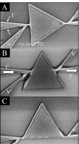
The superconducting triangles are made of a 50-nm-thick Al film thermally evaporated on Si/SiO2. The structures are obtained by deposition through an e-beam patterned resist mask followed by a lift-off procedure. All samples consist of an equilateral triangle with an area of S = 2.2m2 and four wedge-shaped current or voltage contacts. The typical super-conducting coherence length estimated from unpatterned films is about共0兲=120 nm. Three different contact configu-rations are investigated: current injected along a median关see the scanning electron microscopy共SEM兲 image in Fig.1共a兲兴, current injected above the geometrical center关Fig.1共b兲兴, and current injected at the base of the triangle关Fig.1共c兲兴. From hereon, we refer to these samples as sample A, sample B, and sample C, respectively.
The phase boundary for each of the studied samples is summarized in Fig. 2 using an ac drive of 0.1A peak to peak. Here, Tc共H兲 is estimated by a resistance criterion of 10% of the normal state value. The obtained critical tempera-tures Tc共0兲 for samples A, B, and C are 1.365, 1.355, and 1.34 K, respectively. All phase boundaries exhibit clear Little-Parks oscillations with local minima at fields HLwhere the vorticity switches from L to L + 1.19The vertical lines in Fig.2show theoretical estimates of the geometry-dependent transition fields HL for a triangular sample of area S = 2.05m2.20 This value is in good agreement共within 7%兲 with the area estimated from the SEM images shown in Fig. 1. The most obvious feature in Fig. 2 is the different field dependences of Tc for the three studied samples with the higher Tc共H兲 for sample C and lower Tc共H兲 for sample B. Since the only difference between samples is the position of the contact leads, the observed discrepancy in Tc共H兲 can be unambiguously attributed to the influence of these contacts on the nucleation of the superconducting condensate. It is a well established fact21–23 that surface superconductivity is
greatly enhanced in wedge-shaped structures. Since the con-tact leads have a narrower apex angle共15°兲 than the triangle 共60°兲, superconductivity starts to appear at these points first. Under these circumstances, the transition to the supercon-ducting state is expected to occur at higher temperatures in
sample C where both wedges, the contacts and the vertices of the triangle, reinforce the surface nucleation effect. Similar effects were anticipated by de Gennes and Alexander for small superconductor with leads attached to it.24,25
Let us now focus on the interaction of the externally ap-plied currents with the persistent circular currents induced by the magnetic field. In order to resolve better the difference between positive and negative bias currents, we apply an ac drive with amplitude of 10A peak to peak and a frequency of 3837 Hz while measuring the average dc voltage. In this way, when the samples are in the normal state共T⬎Tc兲 or in absence of screening currents共H=0兲, the dc output voltage should be zero, as indeed observed. In contrast to that, if screening currents are present, as a result of an applied non-zero homogeneous field, then the superposition of the ap-plied current with the circulating persistent currents in the triangle gives a different contribution when they reinforce than when they counteract each other. In other words, a net dc voltage signal is recorded. Figure3 shows the measured dc voltage Vdcas a function of the applied magnetic field and temperature⌬T/Tcfor samples A–C. The data are presented here with a parabolic background subtracted, so⌬T=Tc共H兲 −关Tc共0兲−bH2兴, with b a constant different for each sample. In order to make a reliable comparison of the measured sig-nal between different samples, we have normalized Vdc by the distance between the voltage contacts.
Sample B has the same contact configuration as the one earlier reported in Ref.18, with the leads placed above the geometrical center of the triangle. As expected, this sample reproduces the previous results, namely, an abrupt change of sign in the dc response共see the color changes in frames I and II in Fig. 3兲 every time the vorticity of the system changes from L to L + 1, which is associated with the reversal of the persistent currents, and a smooth crossover in between two consecutive HLfields associated with the progressive reduc-tion and later inversion of the screening currents. The origin of the rectified voltage is related to the unbalanced distribu-tion of the external applied current and their compensadistribu-tion with the persistent currents circulating around the geometri-cal center. Since the current leads are located above the geo-metrical center, the applied current mainly flows through the upper part of the triangle, causing an asymmetry by compen-sating 共or reinforcing兲 the screening currents more in the upper part than in the lower part. Schematic drawings of the circulating persistent current and the applied current are shown as an inset in each graph of Fig.3.
Notice that besides the above mentioned voltage sign re-versals related to the Little-Parks oscillations, an unexpected sign reversal is observed in the Meissner phase for sample B 共middle panel in Fig.3兲. The fact that this effect, unlike the Little-Parks oscillations, is much weaker and not systemati-cally observed for all measured samples indicates that it is sample dependent and cannot be related to the circulating screening currents.
According to the above described scenario, if the line along which the current is inserted is not shifted compared to the center of the circulating persistent currents, as in sample A, no rectification effects should be observed. Since the up-per part of the triangle is, in this case, a mirror image of the lower part, the current is distributed equally around the
cen-A
B
C
Γ
I
+I
-V
+V
-FIG. 1. Scanning electron microscopy image of the supercon-ducting equilateral Al triangle of 2.25m side length with wedge-shaped current and voltage contacts with an opening angle⌫=15°.
-4 -2 0 2 4 0.94 0.96 0.98 1.00 T/ Tc µ0H(mT)
FIG. 2. 共Color online兲 Superconductor/normal metal phase boundaries determined by a 10% criterion of the normal state resis-tance. The vertical lines indicate the theoretical expected field val-ues for the Little-Parks oscillations L→L+1 in a triangle with a surface S = 2.05m2.
ter of the triangle and no asymmetry in compensation 共or reinforcement兲 is expected. This is consistent with the strongly reduced signal detected in sample A 共about three times weaker in amplitude and located in a smaller
temperature-field area兲, in comparison with sample B. The origin of this small signal likely lies in the inevitable minor asymmetries produced by shadow effects during the material deposition.
The most compelling evidence that indeed the observed rectification effects originate from the direct superposition of the external current Iappland the field induced persistent cir-cular currents Iper comes from the measurements shown in the lower panel of Fig. 3 corresponding to sample C. In sample C, unlike sample B, the current injection is well be-low the geometrical center of the triangle, and therefore, the situation should be reversed in comparison to sample B. In other words, for the fields where a positive signal is recorded in sample B共indicating that the positive current is reinforced in the top of the triangle兲, an opposite sign is expected for sample C 共i.e., the positive current is compensated at the base of the triangle兲. This reversal between samples B and C is clearly visible for vorticity L = 1 by comparing the indi-cated Secs. I and II with III and IV in Fig.3.
As we already briefly mentioned above, the necessary in-gredients to observe the sort of voltage rectification de-scribed here are共i兲 field induced persistent currents and 共ii兲 off-center injection of external currents. This recipe suggests that similar rectification effects should also be present in ev-ery system with a persistent current and an asymmetric cur-rent path, thus resulting in a difference in critical curcur-rent for a positive or negative applied current. An example of such a system fulfilling these conditions consists of a closed loop with a number N⬎2 of identical Josephson junctions 共JJs兲. A complementary model with N = 2 and unequal JJ has been analyzed recently by Berger.26Without losing generality, the main effects can be seen into two simple configurations: a ring with three junctions and one with five junctions, as sche-matically depicted in Fig.4.
The main assumptions for the calculations are that the superconducting order parameter 共r兲=兩共r兲兩ei共r兲 is such that兩共r兲兩=0, with0the same constant on all islands,共r兲 is spatially constant in each island, and that the weak links between them can be modeled as identical superconductor-normal-superconductor 共SNS兲 junctions. It is also assumed that the total magnetic field B is spatially and temporally constant. The Hamiltonian of a ring with N weak linked SNS junctions is as follows:
H = − EJ
兺
n=0 N−1cos共n− an兲, 共1兲
where EJ is the Josephson energy,n=共rn兲−共rn−1兲 is the phase difference at the junction n = 0 , . . . , N, and共rn兲 is the phase of the superconducting island centered at rn = −R cos共2n/N兲xˆ+R sin共2n/N兲yˆ, with R the ring radius.
The magnetic field contribution to the phase difference anis the line integral of the vector potential between sites n and
n − 1, an= 2 ⌽0
冕
rn−1 rn dl · A共l兲. 共2兲FIG. 3. 共Color online兲 Rectification signal obtained with an ac excitation of 10A and frequency of ⬃3.4 kHz as functions of field and temperature for samples A 共upper panel兲, B 共middle panel兲, and C 共lower panel兲. The vertical lines indicate the theoreti-cally expected field values for the Little-Parks oscillations. The os-cillating dc voltage is presented in a color scale from positive共blue兲 to negative共red兲. The data are presented here with a parabolic back-ground subtracted, so⌬T=Tc共H兲−关Tc共0兲−bH2兴, with b a constant
different for each sample. The inset in each panel gives a schematic drawing of the circulating persistent current共black兲 and the applied current共yellow兲 for that contact configuration.
Taking B = Bz and the gauge A = Bxyˆ for the vector poten-tial A and introducing the flux number through the ring ⌽/⌽0=R2B/⌽0, we have
an= − ⌽
2⌽0兵4/N + sin共4n/N兲 − sin关4共n − 1兲/N兴其. 共3兲 We consider the resistive shunted model using a resistive channel for the normal electron current in parallel with a Josephson current channel, satisfying the Kirchhoff laws for the current conservation in each node. We inject a current I between junctions N − 1 and 0 and extract its ␦ junctions away between junctions␦− 1 and␦. The resulting set of di-mensionless equations for the currents flowing in the ring is as follows:
˙n= Iup− sin共n− an兲, 0 ⱕ n ⱕ␦− 1, 共4兲 ˙n= Iup− I − sin共n− an兲, ␦ⱕ n ⱕ N − 1, 共5兲
Iup⬅ 共1 −␦/N兲I + 1
N
兺
n=0N−1
sin共n− an兲, 共6兲 which are N first order differential equations for the time evolution of the N phase variables兵n其n=0N−1. Let us note that each junction interacts with all the others through
Iup共兵n其n=0N−1兲, the total current in the upper branch of the
cir-cuit, which represents a kind of mean-field interaction plus a drive. The equations can easily be solved numerically by using the Runge-Kutta method in order to compute the in-stantaneous voltage dropv between source and drain, which
can be expressed as v =
兺
n=0 ␦−1 ˙n=␦Iup−兺
n=0 ␦−1 sin共n− an兲. 共7兲 Using this model, the rectified mean dc voltage Vdc=具v典 is calculated as a function of the magnetic field for an ac-sinusoidal current with different amplitudes Iac in the lowfrequency limit. We normalize currents by the single junction critical current I0 and voltages by RNI0, with RN the resis-tance of the resistive channel. The results for N = 3 and N = 5, both with the same source-drain distance ␦= 2, are shown in Fig.4. We can clearly see that both, the N = 5 and the N = 3 devices, can rectify, i.e., 兩Vdc兩⬎0, if ⌽/⌽0⫽n/2 with n an integer and if Iacis above a critical threshold which is smaller for N = 3. We can also observe that the maximum of兩Vdc兩 is almost the same in both cases, although for fixed ⌽/⌽0, Vdcdecays slower as a function of Iacfor N = 3. More importantly, although qualitatively, the same oscillations are observed as in the experiment as a function of vorticity.
The experimental results are measured as a function of temperature with a constant applied current, while in the model, the applied current is changed, keeping the tempera-ture constant. However, the effect is similar since both in-creasing T and Iachave an analogous influence on the system driving it toward the resistive state.
In brief, the predicted rectification in this model system is similar to the effects measured in the Al triangle. It is worth noticing that from the point of view of the superconducting condensate, our experimental system can be regarded as a multiply connected structure since the order parameter is maximum at the vertices and minimum at the sides of the triangle共see the sketch in Fig. 4兲. Furthermore, for certain fields and temperatures,= 0 at the middle of the sides of the triangle and the system can be actually thought of as a ring-like structure with SNS junctions. This scenario is modified by the presence of contact leads which locally enhance the order parameter. In this case, sample B having the contacts at the sides can be directly compared with the five junction rings, whereas the N = 3 rings imitate the response of sample C. Indeed, this association can be further justified by noting in frames I and III共or II and IV兲 of Fig.4that, for the same ⌽/⌽0, the N = 3 and N = 5 Josephson circuits have opposite responses 共for a fixed ␦= 2兲, as it is also found experimen-tally by comparing in the same frames of Fig.3the response of samples B and C for the same H.
In conclusion, we studied the influence of contacts on the rectification effect in superconducting triangles. We demon-FIG. 4. 共Color online兲 Schematic drawing of the superconducting triangle viewed either as a ring of共a兲 N=5 Josephson junctions 共see Fig.1, sample B兲 or 共c兲 N=3 JJ 共see Fig.1, sample C兲, depending on the contact positions. Below, corre-sponding contour plots of the rectified voltage
Vdc, as a function of magnetic flux ⌽/⌽0, and amplitude of the applied ac current Iacfor共b兲 N = 5 and共d兲 N=3. Note the voltage sign difference by comparing equivalent Secs. I and II vs III and IV.
strate that the sign of the rectification voltage depends on the position of the current contacts. These findings are in clear agreement with rectification effects obtained in the frame-work of the theoretical model presenting triangle as a micro-net of identical Josephson junctions.
This work was supported by the K. U. Leuven Research Fund GOA/2004/02 program, the Belgian IAP, the Fund for Scientific Research-Flanders 共F.W.O.-Vlaanderen兲, and by the ESF “Nanoscience and Engineering in Superconductivity 共NES兲” programs.
1A. Libál, C. Reichhardt, B. Jankó, and C. J. Olson Reichhardt,
Phys. Rev. Lett. 96, 188301共2006兲.
2Z. Farkas, P. Tegzes, A. Vukics, and T. Vicsek, Phys. Rev. E 60,
7022共1999兲.
3S. Matthias and F. Muller, Nature共London兲 424, 53 共2003兲. 4R. Gommers, S. Denisov, and F. Renzoni, Phys. Rev. Lett. 96,
240604共2006兲.
5H. Linke, T. Humphrey, A. Lofgren, A. Sushkov, R. Newbury, R.
Taylor, and P. Omling, Science 286, 2314共2003兲.
6I. Zapata, R. Bartussek, F. Sols, and P. Hanggi, Phys. Rev. Lett.
77, 2292共1996兲.
7F. Falo, P. J. Martínez, J. J. Mazo, and S. Cilla, Europhys. Lett.
45, 700共1999兲; E. Trías, J. J. Mazo, F. Falo, and T. P. Orlando, Phys. Rev. E 61, 2257共2000兲.
8D. E. Shalóm and H. Pastoriza, Phys. Rev. Lett. 94, 177001
共2005兲; V. I. Marconi, ibid. 98, 047006 共2007兲.
9Q. Lu, C. J. O. Reichhardt, and C. Reichhardt, Phys. Rev. B 75,
054502共2007兲.
10D. Cole, S. Bending, S. Savelev, A. Grigorenko, T. Tamegai, and
F. Nori, Nat. Mater. 5, 305共2006兲.
11C. C. de Souza Silva, J. Van de Vondel, M. Morelle, and V. V.
Moshchalkov, Nature共London兲 440, 651 共2006兲.
12J. Van de Vondel, C. C. de Souza Silva, B. Y. Zhu, M. Morelle,
and V. V. Moshchalkov, Phys. Rev. Lett. 94, 057003共2005兲.
13J. F. Wambaugh, C. Reichhardt, C. J. Olson, F. Marchesoni, and F.
Nori, Phys. Rev. Lett. 83, 5106共1999兲.
14J. E. Villegas, S. Savel’ev, F. Nori, E. M. Gonzalez, J. V. Anguita,
R. García, and J. L. Vicent, Science 302, 1188共2003兲.
15A. V. Silhanek, W. Gillijns, V. V. Moshchalkov, V. Metlushko, F.
Gozzini, B. Ilic, W. C. Uhlig, and J. Unguris, Appl. Phys. Lett. 90, 182501共2007兲.
16J. Van de Vondel, C. C. de Souza Silva, and V. V. Moshchalkov,
Europhys. Lett. 80, 17006共2007兲.
17S. V. Dubonos, V. I. Kuznetsov, I. N. Zhilyaev, A. V. Nikulov,
and A. A. Firsov, JETP Lett. 77, 371共2003兲.
18M. Morelle, N. Schildermans, and V. V. Moshchalkov, Appl.
Phys. Lett. 89, 112512共2006兲.
19M. Tinkham, Introduction to Superconductivity 共McGraw Hill,
New York, 1975兲.
20L. F. Chibotaru, A. Ceulemans, V. Bruyndoncx, and V. V.
Mosh-chalkov, Phys. Rev. Lett. 86, 1323共2001兲.
21V. M. Fomin, V. R. Misko, J. T. Devreese, and V. V.
Mosh-chalkov, Solid State Commun. 101, 303共1997兲.
22M. Morelle, G. Teniers, L. F. Chibotaru, A. Ceulemans, and V. V.
Moshchalkov, Physica C 369, 351共2002兲.
23V. A. Schweigert and F. M. Peeters, Phys. Rev. B 60, 3084
共1999兲.
24P.-G. de Gennes, Astrophys. Space Sci. 292, 279共1981兲. 25S. Alexander, Phys. Rev. B 27, 1541共1983兲.