HAL Id: hal-00451879
https://hal.archives-ouvertes.fr/hal-00451879
Submitted on 25 Jun 2019
HAL is a multi-disciplinary open access
archive for the deposit and dissemination of
sci-entific research documents, whether they are
pub-lished or not. The documents may come from
teaching and research institutions in France or
L’archive ouverte pluridisciplinaire HAL, est
destinée au dépôt et à la diffusion de documents
scientifiques de niveau recherche, publiés ou non,
émanant des établissements d’enseignement et de
recherche français ou étrangers, des laboratoires
Pantopteron: a New Fully-Decoupled 3-DOF
Translational Parallel Robot for Pick-and-Place
Applications
Sébastien Briot, Ilian Bonev
To cite this version:
Sébastien Briot, Ilian Bonev. Pantopteron: a New Fully-Decoupled 3-DOF Translational Parallel
Robot for Pick-and-Place Applications. Journal of Mechanisms and Robotics, American Society of
Mechanical Engineers, 2009, 1 (2). �hal-00451879�
Sébastien Briot
Dpt. of Automated Manufacturing Engineering École de technologie supérieure
Montreal, QC, Canada sebastien.briot.1@ens.etsmtl.ca
Ilian A. Bonev
ilian.bonev@etsmtl.ca
Pantopteron: a New
Fully-Decoupled 3-DOF
Transla-tional Parallel Robot
for Pick-and-Place
Applica-tions
In this paper, a novel 3-DOF fully decoupled translational parallel robot, called the Pan-topteron, is presented. This manipulator is similar to the Tripteron Cartesian parallel manipulator, but due to the use of three pantograph linkages, an amplification of the ac-tuators displacements is achieved. Therefore, equipped with the same acac-tuators, the mo-bile platform of the Pantopteron moves many-times faster than that of the Tripteron. This amplification is defined by the magnification factor of the pantograph linkages. The kinematics, workspace and constraint singularities of the proposed parallel robot are studied in detail. Design considerations are also discussed and a possible prototype is il-lustrated.
.
1. Introduction
Less than a decade ago, any known parallel robot with three or more degrees of freedom (DOF) was inevitably associated with nonlinear highly-coupled kinematics, singularities, and a com-plex-shaped workspace. In May 2001, a revolutionary simple 3-DOF translational parallel robot, with fully-decoupled input-output equations, was disclosed by Gosselin and Kong in a Cana-dian provisional patent application. Its simplest design, illustrated in Fig. 1(a), is basically a Cartesian robot and is therefore
iso-tropic (its Jacobian matrix is diagonal and constant). After careful
investigation, Kong and Gosselin, helped by the second author of this paper, drafted a patent application that covers all possible de-sign variations. Each of these variations, named Tripteron, is now patent protected in many countries, including USA [1].
Later in 2002, Carricato and Parenti-Castelli [2] and Kong and Gosselin [3][4] proposed separately a large family of decoupled 3-DOF translational parallel mechanisms, all covered by the above-mentioned patent. At the same time, Kim and Tsai [5] pre-sented independently the simplest member of this family (the one shown in Fig. 1(a)).
Who among these three groups of researchers was the first to invent the 3-DOF isotropic parallel robot is not the subject of this paper. In fact, a synthesis of possible legs for the mechanism in Fig. 1(a) was presented in [6] as early as in 1991. What is obvi-ous is that the year 2002 marked the beginning of worldwide research activities on isotropic parallel mechanisms.
The most prolific author on this subject, Gogu, wrote dozens of papers and even a 700-page manuscript [7] proposing isotropic architectures for nearly all combinations of translational and rota-tional degrees of freedom. Among these papers, reference [8] proposes other variations of the Tripteron family. Specific mem-bers
(a) the directions of the actuators are orthogonal.
(b) the directions of the actuators are parallel.
from the Tripteron family were studied in detail in many works (e.g, [9][10] [11][12][13]).
The basic Tripteron parallel robot consists of three identical legs. Each leg has a base-mounted actuator, allowing translation along a fixed direction, and a planar chain. To make the mecha-nism isotropic, the planes of motion of the three planar chains should be orthogonal. Some of the joints of the planar chains may actually be replaced with higher-degree pairs, such as a universal joint, but this has no effect on the kinematics of the mechanism.
In the basic Tripteron, the displacement of the mobile platform along a given Cartesian axis is directly proportional to the dis-placement of each linear actuator. When the plane of the planar chain in a leg is normal to the direction of the corresponding lin-ear actuator (as in the mechanism of Fig. 1(a)), there is a one-to-one relationship, and the Jacobian matrix is the identity matrix. Otherwise, larger displacements are needed from the actuators to produce smaller motions at the mobile platform (as in the mecha-nism of Fig. 1b).
However, as we recently witnessed with the commercialization of the Quattro robot by Adept Technology [14], the only way to compete the hugely successful Delta pick-and-place robot [15] is to offer an even faster design. Hence, it would have been great if we could build a Tripteron with an amplification factor. Not only would this robot be isotropic, but it may move several times faster than its linear actuators.
This paper is the first to provide such a solution through the use of pantographs. Of course, the proposed design is more com-plicated than the simplest Tripteron of Fig. 1(a), but this seems to be a reasonable price to pay. Indeed, the proposed design is the result of a large study on the synthesis of parallel manipulator us-ing pantographs [16]. One such manipulator was already success-fully built and proves the viability of using pantographs [17].
The paper is organized as follows. Next, the kinematics of the proposed design, named the Pantopteron, is presented. The struc-ture is described and its movements are analyzed, as well as their
singularities. Then, its workspace is studied and various design considerations are given. Finally, conclusions are drawn.
2. Kinematic Analysis
2.1. Description of the architecture
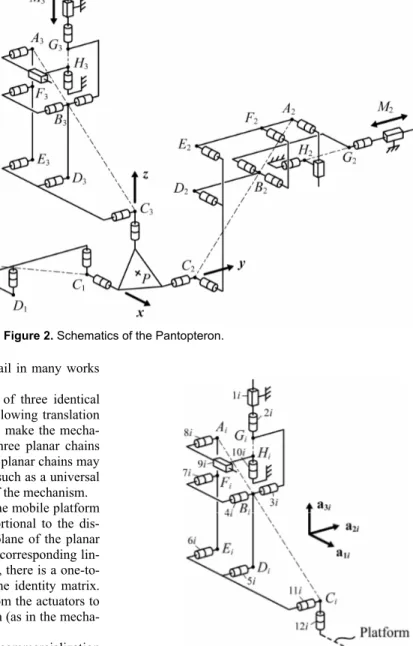
The architecture of the Pantopteron is schematized in Fig. 2. It is composed of three identical legs which correspond to panto-graph linkages (Fig. 3).
The pantograph is a mechanical system with two input points,
Ai and Bi, and one output point Ci (in the remainder of this paper,
i = 1, 2, 3). These input points linearly control the displacement
of the output point Ci. A kinematic analysis shows that a linear
actuator connected with input point Bi controls the vertical
dis-placement of the output point Ci and another linear actuator with
Figure 2. Schematics of the Pantopteron.
an axis parallel to a1i controls the displacements along the same
axis. Note that these motions are completely decoupled, i.e., they can be carried out independently. The input/output relationships for displacements are linear and are determined by the magnifica-tion factor k of the pantograph (k = AiCi/AiBi). These properties of
the pantograph mechanism are used in the Pantopteron.
For the Pantopteron, the actuators are located at the linear pairs (1i) (Fig. 3). These three pairs are connected to the base so that their axes are orthogonal. All other joints are passive. Each pan-tograph linkage is attached to the platform at point Ci via a
Car-dan joint, the axes each joint (12i) being orthogonal. They also are connected to actuator (1i) via a revolute joint, which allows the leg to have five DOFs, three translations and two rotations about the axes of the Cardan joint located at Ci. Such an
architec-ture allows three fully-decoupled translational DOFs. This will be now proved.
2.2. Mobility analysis
Let x, y, z be the axes of the base frame (Fig. 2). Without loss of generality, let us consider the displacements of the platform when legs 2 and 3 are disconnected, as well as the actuator M1 lo-cated at pair (1,1). A simple analysis could show that the platform has five passive DOFs, three translations and two rotations (one about the axis of pair (11,1) and another about the axis of pair (12,1)). Therefore, leg 1 applies one wrench on the platform that constrains its displacements. This wrench is the reciprocal screw to the twists of each passive displacement of the platform.
We denote as ej (j = 1 to 5) the unit screw corresponding to the
passive displacement of the platform. The expression of these screws, expressed in the base frame at point C1, can be written as:
- for the translations along x, y and z,
[
0 0 0 1 0 0]
T 11= e ,[
0 0 0 0 1 0]
T 21= e and[
0 0 0 0 0 1]
T 31= e ;- for the rotations about the axes of pairs (12,1) and (11,1),
[
]
T 0 0 0 sin sin sin cos cos 1 1 1 1 1 41= γ θ γ θ γ e and[
]
T 0 0 0 cos sin 0 1 1 51= − θ θe , where θ1 is the angle
between a11 and y axes, and γ1 represents the rotation between
vector a31 and the axis of pair (12,1).
The Plücker coordinates of the unit screws can be described in matrix E1 as ⎥ ⎥ ⎥ ⎥ ⎥ ⎥ ⎦ ⎤ ⎢ ⎢ ⎢ ⎢ ⎢ ⎢ ⎣ ⎡ − = ⎥ ⎥ ⎥ ⎥ ⎥ ⎥ ⎦ ⎤ ⎢ ⎢ ⎢ ⎢ ⎢ ⎢ ⎣ ⎡ = 0 0 0 cos sin 0 0 0 0 sin sin sin os cos 1 0 0 0 0 0 0 1 0 0 0 0 0 0 1 0 0 0 1 1 1 1 1 1 1 51 41 31 21 11 θ θ γ θ γ θ γ c T T T T T e e e e e E1 (1)
The wrench r11, transmitted to the platform by the leg, is
or-thogonal to the twists composing the lines of matrix E1:
[
rx ry rz 0 0 0]
T 11 11 11 = 11 r (2) with 1 11=−sinγ x r (3a) 1 1 11 =cosθ cosγ y r (3b) 1 1 11=sinθ cosγ z r (3c)Thus, r11 is a wrench of zero pitch (a pure moment).
Similarly, it is possible to find that the wrenches r1i transmitted
to the platform by the legs when all actuators are disconnected are all pure moments. Let Q be the matrix composed of these wrenches applied on the platform by the legs. The expression of
Q in the base frame, and expressed at point O, is:
⎥ ⎥ ⎥ ⎦ ⎤ ⎢ ⎢ ⎢ ⎣ ⎡ = ⎥ ⎥ ⎥ ⎦ ⎤ ⎢ ⎢ ⎢ ⎣ ⎡ = 0 0 0 0 0 0 0 0 0 13 13 13 12 12 12 11 11 11 13 12 11 z y x z y x z y x T T T r r r r r r r r r r r r Q (4)
The twists defining the passive displacements of the platform are orthogonal to this matrix of rank equal to 3. In the general case, there are three independent passive displacements, which are the three translations about x, y and z axes. Thus, the platform is constrained by the legs to have only translational displace-ments.
Note that, in some cases where the three wrenches are linearly dependant, the platform gains one additional DOF. This case will be treated later, in the section about singularities.
Let us now consider that the actuator M1 located at pair (1,1) is fixed. So, due to the decoupling properties of the pantograph link-ages, the position about x axis of point C1 is fixed. Thus, the plat-form has now two passive translational DOFs, which are or-thogonal to the x axis. Therefore, a supplementary constraint is applied on the platform, which restrains its displacement.
Using an approach similar to the previous one, the second wrench applied by the leg on the platform, expressed at point C1,
is =
[
0 0 0 1 0 0]
T21
r .
By a similar analysis, is can be seen that, when the three legs are connected to the platform and the actuators Mi are fixed, six
wrenches (r11, r21, r12, r22, r13, r23) are applied on it. Let us
de-note by R the matrix composed of these wrenches applied on the platform by the legs. The expression of R in the base frame, and expressed at point O, is:
⎥ ⎥ ⎥ ⎥ ⎥ ⎥ ⎥ ⎥ ⎦ ⎤ ⎢ ⎢ ⎢ ⎢ ⎢ ⎢ ⎢ ⎢ ⎣ ⎡ − − − = ⎥ ⎥ ⎥ ⎥ ⎥ ⎥ ⎥ ⎥ ⎦ ⎤ ⎢ ⎢ ⎢ ⎢ ⎢ ⎢ ⎢ ⎢ ⎣ ⎡ = 1 0 0 0 0 0 0 0 sin cos 0 1 0 0 0 0 0 cos 0 sin 0 0 1 0 0 0 0 sin cos 0 3 3 3 3 2 2 2 2 1 1 1 1 23 13 22 12 21 11 C C C C C C T T T T T T y x x z y z θ θ θ θ θ θ r r r r r r R (5)
In this expression, θ1, θ2 and θ3 are the angles between vectors
a11, a12 and a13 and y, z and x axes, respectively. Note that,
ana-lyzing the condition of orthogonality on the axes of pairs (12i), it could be proven that angles γi are constrained to be equal to 0.
Therefore, these terms disappear from Eq. (5).
Without loss of generality, let us consider that actuator M3 is disconnected. Thus, the manipulator gains one passive DOF. The twist corresponding to this passive DOF is the screw t1 which is
orthogonal to the five wrenches applied on the platform,
[
]
T z y x z y x ω ω v v v ω = 1 t (6)where ωx, ωy, and ωz correspond to the rotational velocities of the
platform about x, y and z axes, and vx, vy and vz to its translational
velocities along x, y and z axes. If t1 is a passive motion, the
fol-lowing relation must hold:
[
r11 r21 r12 r22 r13]
t1=0T
(7) As, in Eq. (7), there are five equations for six unknowns (the
Thus, without loss of generality, let us fix the value of vz to 1.
Rearranging Eq. (7) yields:
0 R' = ⎥ ⎥ ⎥ ⎥ ⎥ ⎥ ⎦ ⎤ ⎢ ⎢ ⎢ ⎢ ⎢ ⎢ ⎣ ⎡ ⎥ ⎥ ⎥ ⎥ ⎥ ⎥ ⎦ ⎤ ⎢ ⎢ ⎢ ⎢ ⎢ ⎢ ⎣ ⎡ − − = ⎥ ⎥ ⎥ ⎥ ⎥ ⎥ ⎦ ⎤ ⎢ ⎢ ⎢ ⎢ ⎢ ⎢ ⎣ ⎡ y x z y x C C C C y x z y x v v x z y z v v ω ω ω θ θ θ θ θ θ ω ω ω 0 0 0 sin cos 1 0 0 0 0 cos 0 sin 0 1 0 0 0 sin cos 0 3 3 2 2 2 2 1 1 1 1 (8)
from which, if the matrix is non-singular, t1 can be found as
[
]
T 1 0 0 0 0 0 = 1 t (9)We would like to mention that the case where the matrix R’ is singular will be studied later, in the section about singularities. Thus, throughout the workspace of the mechanism, the permitted passive motion of the platform when actuator M3 is disconnected is a free translation along the z axis. Thus, actuator M3 controls the translation of the platform along the z axis. Moreover, as the axis of actuator M3 is also directed along the z axis, it becomes obvious that, due to the copying properties of the pantograph linkage, a displacement of actuator M3 is transformed on a dis-placement of the platform along the same direction, but amplified by the pantograph linkage.
By similar analyses, it could be proved that actuator M1 (resp.
M2) controls the translation of the platform along the x axis (resp. the y axis). Moreover, a displacement of actuator M1 (resp. M2) is transformed on a displacement of the platform along the same di-rection, but amplified by the pantograph linkage.
Thus, the input-output relations for this manipulator are linear, and it belongs to the family of the fully-decoupled 3-DOF transla-tional parallel mechanisms.
2.3. Geometric and kinematic models, and singularity
analysis
The origin O of the base frame is fixed such that it coincides with point P of the platform when all linear actuators have zero length. It is also considered that an increasing actuator’s length displaces the platform along the positive part of the correspond-ing base frame axis. Therefore, the followcorrespond-ing trivial system of de-coupled linear equations governs the movement of the Pantop-teron:
(
1 x 1)
a1 k x= ρ − G − (10)(
2 y 2)
b2 k y= ρ − G − (11)(
3 z 3)
c3 k z= ρ − G − (12)where k is the magnification factor of the pantograph linkages, x,
y and z are the coordinates of point P of the platform along x, y
and z axes respectively and ρi is the length of actuator i, xG1, yG2
and zG3 are coordinates of points Gi of the platform along x, y and
z axes respectively and a1, b2 and c3 are constant terms defining the shape of the platform (see Eq. (22)).
Since k ≠ 0, the above system of independent equations can be inverted to give the trivial solution to the inverse kinematics of the Pantopteron.
Though simple as it is, the system of independent equations (10-12) can be rewritten in matrix form as
c q J
x= + (13)
where x = [x, y, z]T is the vector of output Cartesian coordinates
and q = [ρ1, ρ2, ρ3]T is the vector of input coordinates, and:
Figure 4. Example of leg singularities.
⎥ ⎥ ⎥ ⎦ ⎤ ⎢ ⎢ ⎢ ⎣ ⎡ = k k k 0 0 0 0 0 0 J (14a)
[
]
T G G G a ky b kz c x k 1+ 1 2+ 2 3+ 3 − = c (14b)Differentiating Eq. (13) leads to
q J
x& = & (15)
Hence, J is the Jacobian matrix of the Pantopteron. Recall that the terms of the Jacobian matrix of the fastest Tripteron are equal to 1. Therefore, the Pantopteron displaces k times faster than the Tripteron (where k is obviously greater than 1). It is also clear
that due to this property, and to the greater number of joints in comparison with the Tripteron, the accuracy of the proposed ro-bot will be lower. However, the purpose of this roro-bot is not to be more accurate, but to be much faster.
One type of singularities occurring in the proposed mechanism is due to the degeneracy of the kinematics of the pantograph legs. Such singularities appear when:
- the parallelograms BiDiEiFi degenerates into a line; near
such case of singularity, the efforts in the revolute joints located at Ei, Fi, Di and Bi grow considerably, so it has to
be avoided by limiting the angle between links (AiEi) and
(EiCi);
- points Ai, Bi and Ci are aligned along the same axis (Fig.
4); in such a case, given one position of the platform, there are infinity of orientations for the pantograph link-age. Moreover, if during a displacement of the mecha-nism, a leg comes close from this singularity, the angular velocity of the pantograph linkage around the axis defined by segment (GiBi) becomes very high. Therefore, the
neighbourhood of such configurations should be avoided by limiting the displacement of pair (9i).
These two kinds of singularity define the boundaries of the workspace. They are similar to the singular configurations that we can meet in the Tripteron.
A second case of singularities appears if the system of wrenches applied on the platform degenerates, i.e., if the matrix
R of Eq. (5) becomes singular. Such a singularity is called a
con-straint singularity [18]. This happens if:
0 sin sin sin cos cos cos ) det(R = θ1 θ2 θ3+ θ1 θ2 θ3= (16)
In such a case, the three moments applied on the platform are linearly dependant, i.e., their axes are parallel or coplanar. Thus, the platform becomes unconstrained and it gains one supplemen-tary DOF.
Let us observe the example presented on Fig. 5. The axis a11 is
Thus, the gained DOF of the platform is a rotation about an axis parallel to the z axis.
Expressing equation (16) in the Cartesian space, it becomes:
0 ) ( ) ( ) ( ) ( ) ( ) ( ) det( 3 2 1 3 3 2 2 1 1 3 2 1 3 3 2 2 1 1 = Γ Γ Γ − − − + Γ Γ Γ − − − = G C G C G C G C G C G C y y x x z z x x z z y y R (17) where 2 1 1 2 1 1 1= (yC −yG) +(zC −zG) Γ (18) 2 2 2 2 2 2 2= (zC −zG ) +(xC −xG ) Γ (19) 2 3 3 2 3 3 3= (xC −xG ) +(yC −yG ) Γ (20)
In these expressions, xCi, yCi, zCi, xGi, yGi, zGi correspond to the
coordinates of points Ci and Gi about x, y and z axes,
respec-tively. Disregarding the case where Γi tends to infinity,
singulari-ties appear when:
0 ) ( ) ( ) ( ) ( ) ( ) ( 3 3 2 2 1 1 3 3 2 2 1 1 = − − − + − − − G C G C G C G C G C G C y y x x z z x x z z y y (21) Taking into account that the terms xGi, yGi, zGi appearing in (21)
are constant and that
T i i i T i =[x,y,z] +[a,b,c] OC (22)
where ai, bi, ci are constant terms, Eq. (21) can be rewritten under
the form: 0 8 7 6 5 4 3 2 1xyz+p xy+p xz+p yz+p x+p y+p z+p = p (23)
where coefficient pi are constant terms depending on the position
of points Gi and of the shape of the platform. Fixing the altitude z
of the platform, Eq. (23) is the expression of a hyperbola, whose coefficients depend on the altitude of the platform and on the geometric parameters of the mechanism.
Fig. 6 presents an example of the constraint singularities in the workspace of a Pantopteron with the following characteristics:
- z = 0.5 m;
- OC1 = [-0.2 m, -0.2 m, 0 m]T, OC2 = [0 m, -0.2 m, 0.2
m]T, OC
3 = [-0.2 m, 0 m, 0.2 m]T;
Figure 6. Example of constraint singularity loci.
- yG1 = zG1 = xG2 = zG2 = xG3 = yG3 = 1 m;
- the parameters of the pantograph linkages are irrelevant, but allow a workspace comprised in the interval x, y ∈ [0 m, 2 m].
We would like to mention that our mechanism, contrary to the Tripteron, has constraints singularities. This is due to the fact that each leg of the Tripteron is attached to the platform by a revolute joint, instead of a cardan joint, which overconstrains the dis-placement of the platform and allows avoiding such singular con-figurations. However, it will be shown in the following section that, even if the Pantopteron has singularities, they can easily be removed from its workspace.
3. Design Considerations
In this part, we will perform the analysis of the workspace of the mechanism, taking into account the geometric limitations and singular configurations, and discuss about some other possible architectures based on this mechanism.
3.1. Geometric workspace analysis
Many parameters influence the size of the workspace of the Pantopteron. As the main parameters, we can mention:
- the lengths of the links of the pantograph;
- on the locations of the axes of the base-mounted revolute joints;
- the shape of the platform;
- the maximal stroke of the actuators and of the passive lin-ear guide;
- the interference between the links; - the singular configurations.
Using the geometric approach, we will compute the workspace of the Pantopteron. As the Pantopteron is a translational parallel mechanism, its workspace can be found as the intersection of three so-called vertex spaces.
Analyzing the vertex space of the leg i, it only depends on: - the lengths of the links of the pantograph;
- the maximal and minimal strokes of the actuators and of the passive linear guide;
- the interferences between the links; - the singular configurations.
In a first step, let us concentrate on the boundaries of the work-space due to the interference of the links and of the singular con-figurations. As mentioned previously, for a leg, there are two types of singularities:
a. when the parallelogram BiDiEiFi degenerates into a line;
such a singularity can be avoided by limiting the angle αi
between the links (AiEi) and (EiCi) of the parallelogram,
which, in the same time, allows limiting some inferences between the links. The maximal and minimal angles will be denoted (αi)max and (αi)min, respectively.
b. when points Ai, Bi and Ci are aligned along the same axis;
such a case can easily be avoided by limiting the stroke of the passive prismatic pair (9i). This minimal stroke will be denoted (si)min.
To avoid interference between the links and the base, a maxi-mal stroke of the actuator has to be fixed at (ρi)max.
Figure 7. Displacement of Ci when αi is fixed.
(a) planar projection of the vertex space.
(b) the 3D vertex space of the leg.
(c) the 3D useful vertex space of the leg.
Figure 8. Schematics of the vertex space of a leg from the
(a) with relatively short legs.
(b) with relatively long legs.
Figure 9. Workspace of the Pantopteron.
Each leg is mounted in rotation around one axis parallel to a3i.
Thus, the problem of finding the vertex space can be limited to a planar analysis of the minimal and maximal displacements of point Ci, the entire vertex space being found by symmetry of
revolution of these displacements.
Considering case (a), we have to find the boundaries of the leg when angle αi is fixed. Fixing angle αi is equivalent to fixing the
lengths of segments (AiBi) and (AiCi). These lengths are equal to:
i EiCi AiEi AiEi EiCi AiCi l l l l l = 2 + 2 −2 cosα (24) k l lAiBi = AiCi/ (25)
Displacing the prismatic guides, segments (AiBi) and (BiCi)
de-scribe Cardanic motions [19][20]. As a result, for a given angle
αi, the displacement locus of point Ci is an ellipse E (Fig. 7).
Thus, considering the extremes (αi)max and (αi)min of angle αi, the
boundaries of the workspace are given by the ellipses Emin and
Emax (Fig. 8(a)).
Cases (b) and (c) are much simpler to analyze. The displace-ment of point Ci when the passive guide (9i) is at its minimal
stroke (si)min is a vertical line L1 located at (k-1) times the
dis-tance (si)min from the vertical axis (GiBi) (Fig. 8(a)). The
dis-placement of point Ci when the actuator Mi is at its maximal
stroke (ρi)max is a horizontal line L2 located at k times the distance between the maximal position of point Bi and the position of
point Ai along the axis a3i, from the axis of the horizontal passive
guide (9i) (Fig. 8(a)).
The entire vertex space is represented at Fig. 8(b). On all of these figures, two boundaries due to two constraints, which are the maximal strokes of the actuated and passive linear joints, are not represented. These boundaries are vertical and horizontal straight lines. However, in a first step, it is preferable to have the largest vertex space for the legs and, thus, to remove these two boundaries out of our workspace by a proper design of the stroke of the linear guides.
As researchers, the first thing on our mind was to implement in Matlab our geometric method in order to be able to optimize the
workspace of the Pantopteron by minimizing the lengths of the pantograph’s links in each leg. This could be done more promptly in a commercial CAD system, such as CATIA [21]. Figure 9(a) shows an example of the workspace of a Pantopteron with rela-tively short legs. We can obtain the best ratio between the lengths of the links and the volume of the workspace. A relatively large increase of the link lengths will result in only a negligible gain in the workspace volume.
Obviously, it would be a mistake to design a Cartesian parallel mechanism with a complex workspace. Thus, our decision is to keep the links as long as it takes, so that the workspace of the mechanism becomes a simple geometric form, namely a rectan-gular parallelepiped. In other words, the workspace of a Pantop-teron with sufficiently long legs has to become a box whose sides are of length k ∆ρi (∆ρi being the stroke of actuator Mi), as shown
in Fig. 9(b).
In order to obtain such a simple volume, when the three vertex spaces are intersected, it is the planar caps that limit the work-space and not the other surfaces. Of course, we still try to mini-mize the length of the links, by carefully locating the prismatic actuators on the base and properly choosing the dimensions of the mobile platform and of the stroke of the actuators. Furthermore, if the workspace of the mechanism has to be a parallelepiped, the shape of the vertex space has not to be so complicated, and can be reduced to a hollow cylinder (Fig. 8(c)). This can be accom-plished by properly constraining the maximal stroke of the active and passive linear guides in order to obtain, in the planar projec-tion of the workspace, a rectangle denoted as the useful vertex space (two possible examples of the useful vertex space are pre-sented in Fig. 8(a)).
The size of the workspace of the Pantopteron is the other main advantage of the proposed robot. Indeed, the maximal volume of the workspace of the Tripteron is V = ∆ρ1∆ρ2∆ρ3 while that of the Pantopteron is V = k3∆ρ1∆ρ2∆ρ3, i.e., for the same set of given actuators, the workspace of the Pantopteron is k3 times bigger than that of the Tripteron.
Moreover, it is well known that the actuators represent at least 80% of the global cost of for a robot. For creating a fast mecha-nism with actuated prismatic pairs, it is now preferable to use electric linear actuators that reach higher velocities. However, the main drawback of such actuators is their price, which is propor-tional to the length of their stroke. For a given maximal work-space, the stroke of the actuators of the Tripteron is k times greater than that of the motors of the Pantopteron. Therefore, even if the Pantopteron is more complicated to design than a Tripteron, its manufacturing cost would likely be lower.
3.2. Singularity-free workspace
It is impossible to speak about the workspace of a parallel mechanism without dealing with singularities. As seen previously from Eq. (23), the singular configurations depend on the position of the mobile platform, on the locations of the axes of the base-mounted revolute joints, and on the shape of the platform. Thus, analyzing Eq. (23), there are twelve design parameters which are
yG1, zG1, xG2, zG2, xG3, yG3, b1, c1, a2, c2, a3 and b3 (we do not con-sider the lengths of the links of the pantograph linkages as they do not influence these singular configurations). So, there is too much parameter in order to perform a complete analysis of the singular configurations. However, it is possible to restrict our
analysis to some particular designs, which will decrease the num-ber of parameters.
Thus, we will consider in this part a mechanism which will have a platform with two axes concurrent (for example for pairs (12,1) and (12,3)), and a base of which two axes of actuators are also concurrent (for example those of actuators M1 and M2). Therefore, considering that the intersection point of the axes of actuators M1 and M2 is the origin of the base frame, and that point
P is at the intersection of the two axes of the platform, only xG3,
yG3, a3 and b3 stay variable, the other ten parameters being equal
to zero.
In such a case, equation (23) becomes:
(
) (
)
(
2xy+y a3−xG3 +x b3−yG3)
=0z (26)
Thus, singular configurations will appear if the platform of the mechanism is located in the plane P1 (z = 0), or if it is located on a hyperbola H whose expression is:
(
) (
)
02xy+y a3−xG3 +x b3−yG3 = (27)
Please note that this expression does not depend on the altitude
z of the platform. It is well known that such a hyperbola has two
asymptotes,
(
y 3 b3)
/2y= G − (28)
(
x 3 a3)
/2x= G − (29)
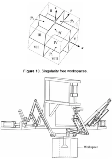
which, in 3D, represent two planes P2 and P3. Thus, the Carte-sian space may be separated into eight regions (Fig. 10). In re-gions I, III, V and VII, there are no singularities and it will be quite easy todevelop a manipulator of which the workspace is lo-cated in these regions, taking into account the previous geometric approach. In regions II, IV, VI and VIII, even if there are singular configurations, they are quite close from the planes P2 and P3, and thus, it is also quite easy to inscribe a cube representing the workspace of the mechanism in these regions.
Please note that in the special cases where all parameters are equal to zero, or a3 = xG3 and b3 = yG3, Eq. (26) becomes
0
2xyz= (30)
Thus, the hyperbolas degenerates into two straight lines of equations x = 0 and y = 0. Therefore, the eight regions delimited by planes Pi have no singularities.
A possible version of a prototype of a Pantopteron is repre-sented at Fig. 11. Its geometric parameters are:
- lAiEi = 0.2 m, lEiCi = 0.3 m, k = 3;
- yG1 = zG1 = xG2 = zG2 = xG3 = yG3 = 0 m, b1 = c1 = a2 = c2 = a3 = b3 = 0 m;
- actuator strokes = 0.06 m ((zi)min = -0.22 m, (zi)max = -0.16
m)
- passive linear guide strokes = 0.14 m ((si)min = 0.01 m, (si)max
= 0.15 m) ;
- (αi)min = 25°, (αi)max = 155° ;
Its design is achieved such as its workspace is a cube whose side is equal to 0.18 m.
3.3. Other possible architectures
Finally, we would like to mention that the design of the Pantop-teron presented here is not the only solution for creating such a mechanism. First, as the leg is made up of a pantograph linkage, several design are possible, which are presented in [22]. How-ever, we think the architecture we proposed is the most practical one. Moreover, note that the planar RP chain composed of the
revolute joint (10i) and the prismatic joint (9i) could be removed and replaced by any kinematic chain able to perform a planar dis-placement, as planar RRR, RPR, PPR or PRR chains. Moreover, using such chains, points Hi and Gi need not be aligned.
Note also that other architectures with various DOFs are possi-ble by modifying our Pantopteron, such as the mechanism with 4 decoupled DOFs represented it Fig. 12.
Figure 10. Singularity free workspaces.
Figure 11. CAD view of the prototype of Pantopteron.
4. Conclusions
In this paper, a novel 3-DOF fully-decoupled isotropic transla-tional parallel mechanism, named the Pantopteron, was presented. This mechanism is very similar to the Tripteron Cartesian parallel mechanism, but due to its architecture which is made of three pantograph linkages, an amplification of the movements between the actuators and the platform displacements is achieved. There-fore, the Pantopteron displaces k times faster than the Tripteron (k being the magnification factor of the pantograph linkages). More-over, for a given set of actuators, its workspace is k3 times bigger than that of the Tripteron. Due to this property, if the size of the workspace is given, the stroke of the actuators of the Pantopteron is k times smaller than that of the Tripteron, which allows reduc-ing the manufacturreduc-ing cost. This novel mechanism is foreseen to be used in applications where the velocities and accelerations have to be high, such as in pick-and-place.
5. References
[1] Gosselin, C.M., and Kong, X., 2004, “Cartesian Parallel Manipulators,” US patent 6,729,202, filed July 8, 2002, and issued May 4, 2004.
[2] Carricato, M., and Parenti-Castelli, V., 2002, “Singularity-Free Fully-Isotropic Translational Parallel Manipulators,”
The International Journal of Robotics Research, Vol. 21,
No. 2, pp. 161–174.
[3] Kong, X., and Gosselin, C.M., 2002, “Type Synthesis of Linear Translational Parallel Manipulators,” Advances in
Robot Kinematics: Theory and Applications, J. Lenarcic, F.
Thomas, eds., Kluwer Academic Publishers, pp. 453–462. [4] Kong, X., and Gosselin, C.M., 2002, “A Class of 3-DOF
Translational Parallel Manipulators with Linear Input-Output Equations,” Proceedings of the Workshop on
Fundamental Issues and Future Research Directions for Parallel Mechanisms and Manipulators, Quebec City,
Quebec, Canada, October 3–4, pp. 25–32.
[5] Kim, H.S., and Tsai, L. W., 2002, “Evaluation of a Cartesian Parallel Manipulator,” Advances in Robot Kinematics:
Theory and Applications, J. Lenarcic, F. Thomas, eds.,
Kluwer Academic Publishers, pp. 21–28.
[6] Hervé, J.M., and Sparacino, F., 1991, “Structural Synthesis of Parallel Robots Generating Spatial Translation,”
Proceedings of the 5th IEEE International Conference on
Advanced Robotics, Pisa, Italy, pp. 808–813.
[7] Gogu. G., 2008, Structural Synthesis of Parallel Robots,
Part 1 – Methodology, Springer, the Netherlands.
[8] Gogu, G., 2004, “Structural Synthesis of Fully-Isotropic Translational Parallel Robots via Theory of Linear Transformations,” European Journal of Mechanics A/Solids, Vol. 23, No. 6, pp. 1021–1039.
[9] Carricato, M., and Parenti-Castelli, V., 2004, “A Novel Fully Decoupled 2-DOF Parallel Wrist,” The International
Journal of Robotics Research, Vol. 23, No. 6, pp. 661–667.
[10] Callegari, M., Palpacelli, M. and Scarponi, M., 2005, “Kinematics of the 3-CPU Parallel Manipulator Assembled for Motions of Pure Translation,” Proceedings of the 2005
IEEE International Conference on Robotics and Automation (ICRA), Barcelona, Spain.
[11] Ruggiu, M., 2008, “Kinematic Analysis of the CUR Translational Manipulator,” Mechanism and Machine
Theory, Vol. 43, No. 9, pp. 1087–1098.
[12] Lee, C.-C., and Hervé, J.M., 2007, “Cartesian Parallel Manipulators with Pseudoplanar Limbs,” Journal of
Mechanical Design, Vol. 129, pp. 1256–1264.
[13] Li, W., Zhang, J., and Gao, F., 2006, “P-CUBE, A Decoupled Parallel Robot Only with Prismatic Pairs,”
Proceedings of the 2nd IEEE/ASME International Conference on Mechatronic and Embedded Systems and Applications, Beijing, China.
[14] Pierrot, F., Nabat, V., Company, O., Krut., S., and Poignet, P., 2008, “Optimal Design of a 4-dof Parallel Manipulator: From Academia to Industry,” IEEE Transactions on
Robotics, in press.
[15] Bonev, I.A., 2001, “Delta Robot — the Story of Success,”
on-line article available at www.parallemic.org/Reviews/Review002.html.
[16] Briot, S., Arakelian, V., and Guégan, S., 2008, “PAMINSA: a New Family of Decoupled Parallel Manipulators,”
Mechanism and Machine Theory, in press.
[17] Briot, S., Arakelian, V., and Guégan, S., 2008, “Design and Prototyping of a Partially Decoupled 4-DOF 3T1R Parallel Manipulator with High-Load Carrying Capacity,” Journal of
Mechanical Design, in press.
[18] Zlatanov, D., Bonev, I. A., and Gosselin, C.M., 2002, “Constraint Singularities of Parallel Mechanisms,” IEEE
International Conference on Robotics and Automation (ICRA 2002), Washington, D.C., USA, May 11–15.
[19] Sekulie, A., 1998, “Method of synthesis of Cardanic motion,” Facta Universitatis, Mechanical Engineering, University of NIS, Vol. 1, No. 5, pp. 565–572.
[20] Tischler, C.R., Hunt, K.H., and Samuel, A.E., 1998, “A Spatial Extension of Cardanic Movement: Its Geometry and Some Derived Mechanisms,” Mechanism and Machine
Theory, Vol. 33, No. 8, pp. 1249–1276.
[21] Bonev, I.A., and Ryu, J., 2001, “A Geometrical Method for Computing the Constant-Orientation Workspace of 6-PRRS Parallel Manipulators,” Mechanism and Machine Theory, Vol. 36, No. 1, pp. 1–13.
[22] Lu, D.-M., and Hwang, W.-M., 1996, “Synthesis of Planar Five-Bar Pantograph Configurations by a Geometric Method”, Mechanism and Machine Theory, Vol. 31, No. 1, pp. 11–21