HAL Id: inria-00628310
https://hal.inria.fr/inria-00628310
Submitted on 1 Mar 2013
HAL is a multi-disciplinary open access
archive for the deposit and dissemination of
sci-entific research documents, whether they are
pub-lished or not. The documents may come from
L’archive ouverte pluridisciplinaire HAL, est
destinée au dépôt et à la diffusion de documents
scientifiques de niveau recherche, publiés ou non,
émanant des établissements d’enseignement et de
Flex-eWare: a Flexible MDE-based Solution for
Designing and Implementing Embedded Distributed
Systems
Mathieu Jan, Christophe Jouvray, Fabrice Kordon, Antonio Kung, Jimmy
Lalande, Frédéric Loiret, Juan Navas, Laurent Pautet, Jacques Pulou, Ansgar
Radermacher, et al.
To cite this version:
Mathieu Jan, Christophe Jouvray, Fabrice Kordon, Antonio Kung, Jimmy Lalande, et al.. Flex-eWare:
a Flexible MDE-based Solution for Designing and Implementing Embedded Distributed Systems.
Software: Practice and Experience, Wiley, 2012, 42 (12), pp.1467-1494. �10.1002/spe.1143�.
�inria-00628310�
Flex-eWare: a Flexible MDE-based Solution for
Designing and Implementing Embedded
Distributed Systems
Mathieu Jan5, Christophe Jouvray2, Fabrice Kordon1, Antonio Kung2, Jimmy Lalande6, Fr´ed´eric Loiret8, Juan Navas4, Laurent Pautet3,
Jacques Pulou4, Ansgar Radermacher5, Lionel Seinturier7
1 Univ. P. & M. Curie, LIP6, CNRS UMR-7606, 4 place Jussieu, 75005 Paris, France
2 TRIALOG, 25 rue du G´en´eral Foy, 75008 Paris, France 3 Telecom ParisTech, 46 rue Barrault, 75013 Paris, France 4 Orange Labs, 28 chemin du vieux Chˆene, 38243 Meylan, France 5 CEA, LIST, Gif-sur-Yvette, 91191 France
6 Schneider Electric Industries, Strategy & Innovation, 38050 Grenoble, France 7 Univ. Lille 1 & INRIA, LIFL, CNRS UMR-8022, 59655 Villeneuve d’Ascq, France
8 Royal Institute of Technology (KTH), Embedded Control Systems, Stock-holm, Sweden
Abstract
The complexity of modern embedded systems increases as they incor-porate new concerns such as distribution and mobility. These new features need to be considered as early as possible in the software development life-cycle. Model Driven Engineering (MDE), that promotes an intensive use of models and is now widely seen as a solution to master the development of complex systems such as embedded ones. Component-Based Software Engineering (CBSE) is another major trend that gains acceptance in the embedded world due to its properties such as reuse, modularity and flex-ibility.
This article proposes the Flex-eWare Component Model (FCM) for designing and implementing modern embedded systems. The FCM uni-fies MDE and CBSE and has been evaluated in several application do-mains with different requirements: wireless sensor networks, distributed client/server applications, and control systems for electrical devices. This approach highlights a new concept: flexibility points, that arise at sev-eral stages of the development process: in the model (design phase), in the execution platform and during the execution itself. This flexibility points are captured with model libraries that can extend the Flex-eWare Component Model.
1
INTRODUCTION
Embedded systems tend to be more and more complex and incorporate many different concerns such as distribution and mobility. This raises a need for new features to be considered during their development such as architecture descrip-tion, deployment strategies, extensibility or to consider runtime adaptation in such systems.
From a software engineering point of view, Model Driven Engineering (MDE) is now widely seen as a solution to master the development of complex systems such as embedded systems. In such approaches, development relies on models that are able to support code generation to ease and secure implementation on one hand, to enable reasoning and to check properties such as schedulability on another hand.
However, current notations to support the design of embedded systems do not consider yet the new required features that could help the designer to cope with the new needs of embedded systems. In particular, embedded systems have to be flexible. This is critical since engineers will have, sooner or later, to cope with various types of embedding constraints (e.g. the one of Systems on Chip and the one of workstations) in the same application. So, flexibility can help in the design of embedded systems either at design time (software product line or configuration/deployment) or at runtime (adaptability).
The Flex-eWare project [1] aims at developing a solution to cope with flexi-bility in the design of embedded and distributed systems. This project gathered companies (Orange Labs, Schneider Electric, Teamlog, Thales, Trialog) and academics (CEA, INRIA, Telecom ParisTech, Universit´e P. & M. Curie) from 2007 to 2010. This article presents the results of this project from both the conceptual point of view (what has to be set up in the specification) and the development process. We first elaborate a conceptual component model: FCM (Flex-eWare Component Model). Then, we design some mappings to several technologies in order to assess its generality.
This article is structured as follow. Section2 identifies the problems to be tackled by future embedded and distributed systems. Section 3 presents some existing (and usually partial) solutions proposed in the area and outlines the main concepts considered to elaborate FCM. Section 4 details our component models and its specificities. Section5illustrates the use of FCM in three different application domains with different underlying technologies. Finally, Section 6
concludes this article and proposes directions for future work.
2
REQUIREMENTS
This section identifies the set of requirements related to a model-based design approach for complex systems. We do so by studying the domains targeted by our work (Section 2.1). In particular, we emphasize the management of flex-ibility that is a key issue for future embedded and distributed systems. We then identify how flexibility management should impact the software engineer-ing life-cycle (Section 2.2) and introduce our contribution to these challenges (Section2.3).
2.1
Requirements for Future Application Domains
Let us first provide examples of current and future needs on software flexibility in two application domains that are emblematic of the domains targeted in our work: Customer Premise Equipment (CPE) and automotive systems. Future needs are based on a prospective vision of these domains.
Telecommunication CPE domain. The CPE market in telecommunication refers to products installed at home, connected to an external network and operated by business operators. Typical examples are Internet modems and ”boxes”. Such systems provide multiple services such as Internet access, IP TV, Video on Demand (VoD) and voice over IP.
Today, business operators need software architectures as well as deployment features suitable to maintain, update, extend and configure applications for CPE such as new video encoders. Due to the various home network solutions [2,3], they also need to support non functional requirements, like QoS management. Both types of functions are needed, for instance to replace a security component within an existing video encoder. Operators also have to cope with numerous devices (e.g. millions of Internet boxes) and therefore need features for scalable remote administration [4], deployment [5] and configuration inspection [6].
In the future, the market will move towards richer services as well as more sophisticated services involving multiple stakeholders. For instance, such ser-vices could be aggregators. Competing operators may thus coexist and have to share the management of CPE devices that would then have to cope with dynamically changing environments. In this context, Service Oriented Architec-ture (SOA [7]) approaches will be required to enable new software components to be dynamically downloaded, deployed, registered and linked to existing ones (possibly designed by other operators).
Automotive Systems. The automotive industry is currently targeting sup-ply environments based on a vehicle manufacturer-centric relationship involving components from various sources in order to ensure both lower costs and lower risks of supply shortage. They are also concerned by stringent contractual and liability obligations. So, automotive systems need to support complex prod-uct diversity, either because vehicles come with customer options (e.g. type of engine, accessories, etc.), or because the assembly of vehicles involves multi-sourcing options.
Software is now a major part of these supply environments. It has been reported [8] that the development of automotive systems has already reached 40% of the total vehicle development cost, with a major part dedicated to the software part. Diversity of sources is ensured using software structuring stan-dards such as Autosar [9], which allow the construction of systems based on the reuse of both applications and system components.
Some vehicles today include up to 70 electronic control units (ECU). It is anticipated that, for costs issues, vehicle functions will soon be deployed over a smaller number of ECUs. For instance, four cluster functions could be foreseen: power-train, body, safety, and multimedia. So, software components will have to be reused in configurations involving modifications of non functional properties. Moreover, an increasing number of external multimedia functions will also be installed in vehicles such as navigation systems, road tolling systems
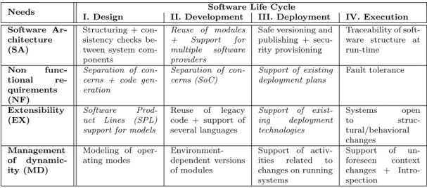
Table 1: Requirements over the software life-cycle (mains objectives of Flex-eWare are outlined in italic)
Needs Software Life Cycle
I. Design II. Development III. Deployment IV. Execution
Software Ar-chitecture (SA)
Structuring + con-sistency checks be-tween system com-ponents
Reuse of modules + Support for multiple software providers
Safe versioning and publishing + secu-rity provisioning Traceability of soft-ware structure at run-time Non func-tional re-quirements (NF) Separation of con-cerns + code gen-eration Separation of con-cerns (SoC) Support of existing deployment plans Fault tolerance Extensibility (EX) Software Prod-uct Lines (SPL) support for models
Reuse of legacy code + support of several languages Support of exist-ing deployment technologies Systems open to struc-tural/behavioral changes Management of dynamic-ity (MD) Modeling of oper-ating modes Environment-dependent versions of modules Support of activ-ities related to changes on running systems Support of un-foreseen context changes + Intro-spection
or insurance systems based on usage. Integration of such functions will require more dynamicity in the underlying execution environment. This will have an impact on the way software components are developed and deployed.
Summary. Based on these two examples, some directions are emerging for software embedded systems. First, software flexibility must be considered all over the product life-cycle (i.e., design, development, deployment and during execution, see next section). We call flexibility points the specific cut-points during the development phases when variants are available to engineers (and thus flexibility of solutions can be investigated).
Second, flexibility must cope with the following needs: suitable software structuring, management of non functional aspects, management of extensibility and management of dynamically changing environments.
2.2
Requirements for Future Embedded Systems
Section2.1identified future and near-future needs shared by both the automo-tive and CPE domains. These needs can be easily extended to other domains of embedded and distributed systems. In order to identify how software engi-neering should satisfy these requirements, we explore the way they are reflected throughout the product development life-cycle. In order to simplify our study, we consider a rather ad-hoc software life-cycle, coarsely based on the Waterfall model [10] and composed of the following phases: design, development, deploy-ment and execution.
We extract a list of requirements to be fulfilled by embedded software en-gineering models. This list is described extensively in the remainder of this section and is summarized in Table1. Columns refer to the software life-cycle phases, rows to general needs. For example, the cell III.MD at the intersection of column Deployment (III) and row Management of dynamicity (MD), provides the requirements for dynamicity during the deployment phase.
2.2.1 Requirements for the Design Phase.
This phase deals with the specification of software requirements. In our case, this corresponds to the process of planning a solution satisfying these requirements. Designers may describe behavioral and structural aspects of a design solution using standard languages such as UML, formal languages such as B [11], or architecture description languages [12] such as Wright [13]. Requirements for the design phase are reported as follows:
• I.SA: Structuring and Consistency checks between system com-ponents. This includes features such as encapsulation with arbitrary granularity, strict separation of design aspects, modularity and hierarchy support, in order to provide different system views at different abstrac-tion levels. Expressing component needs and relate them to the associated provided services on the invoked side, it is possible to ensure several con-sistency properties early in the design phase. For instance, it is possible to check that a client-side maximum allowed delay is compatible with a server-side maximum guaranteed delay.
• I.NF: Separation of concerns and Code generation. Functional and non functional aspects of a system should be modeled separately at the ap-propriate development step. Domain-specific concerns may be abstracted and thus captured at a high level. Then, code generator are able to gener-ate the approprigener-ate code dealing with non functional requirements for the targeted domain (similarly to Aspect-Oriented Programming – AOP [14]). • I.EX: Software Product Lines (SPL) support for models. Current modeling languages propose features tailored for particular application domains. When unifying several languages, there are two ways to handle these variations: i) building a unified model, or ii) build a model with flex-ibility points. These flexflex-ibility points enable the definition of extensions to tailor the original language to a specific need. Thus, the specification language can be designed and adapted as in a Software Product Line. • I.MD: Modeling of operating modes. Dynamic evolution of a system
can be expressed thanks to the definition of several operating modes and the interaction between these modes. This solution have been adopted in AADL V2 [15]. Association of mode switch with mechanisms such as introspection (configuration discovery) or intercession (change on system configuration) is handled via an appropriate runtime.
2.2.2 Requirements for the Development Phase.
This phase deals with the concrete implementation of the designed system. It also contains testing, debugging, validation and integration of the produced systems. In some cases, design standards may require some characteristics of development process, such as code modularity or programming language. Re-quirements for the development phase are reported as follows:
• II.SA: Reuse of modules and Support for multiple software providers. Reuse of independently-developed software source code modules decreases the development effort and eases maintenance tasks through sharing of
maintenance-operations experiences on independent systems. This has a direct impact over business-related metrics and, in particular, the time-to-market.
System modules may also be implemented in parallel by several providers. Such an approach is typically used in the automotive domain where com-peting suppliers provide modules to more than one integrator. This re-quires specific support in the involved modeling languages as well as in the underlying runtime (e.g. AUTOSAR in automotive systems).
• II.NF: Separation of concerns (SoC) at a source code level. SoC is a key principle in software development. Several concerns such as run-time error treatment and communication protocols in distributed systems, could be identified and separated to reduce complexity. Then, they are combined by the tool chain in order to produce the system implementation. This approach is also similar to the one of Aspect-Oriented Programming. • II.EX: Reuse of legacy code and Support of several languages. Complex systems may integrate pre-existing modules built using different development paradigms, or no paradigm at all. Any new model or frame-work must consider this case and provide appropriate tools and mecha-nisms to integrate legacy code. There is a similar problem with program-ming languages since different components may have been implemented using several languages.
• II.MD: Environment-dependent versions of modules. There is a need to manage several implementations of a given module, each one being able to cope with some non functional requirements. For instance, several versions of a MPEG-4 decoder may be built for different energy consumption profiles.
2.2.3 Requirements for the Deployment Phase.
This phase deals with releasing, packaging and installing of a system to enable its use by customers. Requirements for the deployment phase are reported as follows:
• III.SA: Safe versioning, publishing and security provisioning. There is a need to maintain consistency between versions of the various components that compose a system. For instance, backward compatibil-ity of a component induces constraints on the versions of the depending software pieces. When publishing such systems, some dynamic linking mechanisms may be required. These mechanisms can be based on the description of provided and required, similarly to OSGi Manifests. The identification of critical modules is important to enable safe deployment policies and protect Intellectual Property (IP). For instance, AUTOSAR defines mechanisms to identify faulty components and protect modules implementation.
• III.NF: Multiple deployment policies/models support. Several deployment plans could be defined in order to match with several configu-ration requirements. For instance, according to the components installed
in the host platform and the network capabilities, source-code or binary content delivery may be considered.
• III.EX: Support of existing deployment technologies such as pack-age manpack-agers, content delivery technologies and standard file formats. • III.MD: Support of activities related to changes on running
sys-tems, such as actions coordination, secured transmissions and new con-tents (data and/or code) delivery. For instance, regarding content delivery, we identify two approaches commonly used in the CPE domain. In the Push approach, newly released software is push onto the device by the operator. In that case delta upload allowed by Component paradigm is of paramount interest thanks to scalability when millions of devices have to be simultaneously upgraded. In the Pull approach, devices require new functionalities according to their needs, e.g. the UPnP service discovery mechanisms.
2.2.4 Requirements for the Execution Phase.
This phase should be reduced to the interpretation of computer program in-structions by a physical processor or a virtual machine. It also deals with other activities like maintenance, update, adaptation and evolution of the system. Requirements for the execution phase are reported as follows:
• IV.SA: Traceability of software structure at run-time. Allowing identification of sub modules that are prone to change, by establishing an isomorphism between executing code and the model. By these meanings, software behavioral modifications may be expressed as structural modifi-cations, easing localized maintenance, adaptation and evolution activities. • IV.NF: Fault tolerance. Changes in the execution environment may lead to new non functional requirements. For instance, bad data retrieved from a broken sensor should be handled and the source redirected to get appropriate data from other sources (e.g. via the network). In that case, a new communication link must be dynamically established to maintain the system reliability.
• IV.EX: Systems open to structural/behavioral changes. Execu-tion runtime must be able to dynamically support structural and/or be-havioral extensions. Flexibility points can be used to define runtime re-strictions with regards to these changes.
• IV.MD: Support of unforeseen context changes and Introspec-tion. In some case, system dynamicity cannot be specified at an early stage of its life-cycle. Thus, models and frameworks should still provide tools and execution runtimes enabling system adaptation to such changes. Introspection mechanisms are required to enable system adaptation. For instance, getting the quality of a given component service is required to evaluate whether or not this component may be part of a dynamic service composition.
2.3
Covered Needs
Table 1 proposes a full view on the need for future embedded systems. This paper reports on a subset of them which were the focus of the Flex-eWare project (noted in italic in the table) : I.NF, I.EX, II.SA, II.NF, III.NF, III.EX.
These needs mainly deal with flexibility at design and development. One of the main goals of Flex-eWare is to encapsulate technologies into a notation dedicated on concepts and suitable for domain specific extensions (this is de-tailed in Section4). This enables the support of MDE technologies to propose various mapping as shown in Section5(mapping is performed on three different technologies: Fractal, eC3M and OASIS).
Two others requirements are also partially covered in the Flex-eWare Project: II.EX and IV.SA. The encapsulation mechanism eases the reuse of legacy com-ponents (II.EX) and helps to increase traceability of the software architecture (IV.SA).
Other needs are more difficult to cover so far. This is in particular the case for the management of dynamicity (MD line in Table1). Needs like I.SA (con-sistency checks) or IV.NF (fault tolerance) are more related to methodological issues and are not in the scope of the Flex-eWare project.
3
STATE OF THE ART
This section presents some state of the art projects for designing and imple-menting flexible embedded systems. We deliberately put some emphasis on the work that was part of the Flex-eWare project legacy (in the sense this was tech-nologies better known in this context). The main reason is that we took most of our inspiration from this knowledge to set up the Flex-eWare Component Model (FCM).
Sections 3.1 to 3.3 briefly introduce each of these building blocks: EC3M, Fractal and OASIS. To do so, we use the criteria identified in the previous sec-tion: architecture design and development, deployment, runtime, non functional aspects and extensibility. Then, Section3.4reviews some other existing projects that have similar objectives but were not a main source of inspiration for FCM.
3.1
EC3M
The embedded Component Container Connector Middleware (eC3M)1is an in-tegrated approach for designing embedded systems. eC3M promotes a component-based approach which is aligned with the OMG Deployment & Configuration (D&C) [16] and CCM [17] standards. Components and connectors are the two core artifacts provided by eC3M for designing embedded systems.
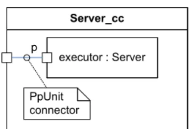
Architecture Design & Deployment. Connectors are specific kinds of components implementing interactions. The main difference is that they need to be adapted to the context in which they are used: for instance, a connec-tor implementing an asynchronous method invocation must adapt to a specific interface that is used between two application components.
Containers shield the business logic of a component from its environment. Container services may either intercept incoming or outgoing requests or imple-ment an additional functionality that is not provided by the business logic itself (called executor in the CCM [17] terminology). An interceptor is a specific kind of connector.
eC3M uses the UML profile MARTE [18] (Modeling and Analysis of Real-Time and Embedded systems) to define a set of UML extension targeted to real-time embedded systems. It is structured into packages covering founda-tions, design, analysis and annexes. The foundation package covers among other aspects non-functional properties (NFPs). The NFPs are defined in a generic way, allowing to define specific properties by means of a standardized model library.
Non-functional properties such as deadlines, jitter and memory budgets play an important role in the definition of real-time embedded systems, since the correctness of the system requires that all non-functional requirements are met. The MARTE library standardizes frequently used properties such as durations and arrival patterns. The elements of the library are typically datatypes whose attributes may cross reference to NFP types. An example is the real-time feature data type which has a relative deadline attribute typed as a NFP duration. Another attribute is an arrival pattern having different specializations. With respect to flexibility, it is important that NFP types are defined in a library and are thus extensible to suit domain needs.
Extensibility. Connectors and container services are not fixed, they can be defined in model libraries in a quite similar way as application components are. An application model may import the model libraries that are suitable for the application domain. The libraries are thus the primary extension mechanism in eC3M.
As already mentioned, the main difference between components and connec-tors is the ability of the latter to adapt themselves to a usage context. This ability is modeled by means of UML templates, i.e. the possibility to refer to formal parameters like for instance a port type. In a template instantiation process, the formal template parameter is bound to an actual parameter. Im-plementations are instantiated as well and may be defined by means of Acceleo2
templates.
The extensibility in terms of containers and connectors enables an adapta-tion to the applicaadapta-tion domain, in order to define software product lines and to manage variability. Sub-components within a composite may optionally be specified via a type instead of an implementation. If this is done, the choice of the implementation to use is delayed until the deployment phase, when in-stances and their allocation are defined. The implementation choice may depend on the allocation, i.e., on properties of the node (such as available space, OS and processor architecture). Another aspect is that the use of different connec-tors facilitate the use of different deployment architecture, e.g., a deployment architecture in an automotive platform.
Run-Time Adaptation. The focus of eC3M is currently on statically de-ployed applications. It is possible to change the assembly by re-connecting ports
and instantiating components at runtime. However this must be done program-matically, i.e. one of the applications components must explicitly instantiate new components and call the port connection operations. Current work aims to express variability at model level and support automated transitions between the variants. In this context, we also seek to support the update of components implementations and the re-instantiation of existing components with a new implementation.
3.2
Fractal
Fractal [19] is a hierarchical, reflective and open component model. Fractal components can be nested at any arbitrary level of granularity required by the modeled system, component assemblies can be navigated to discover and modify at runtime the architecture of an application and the component containers can be programmed to customize the hosting and execution semantics. The Fractal component model is independent from programming languages and runtime supports exist for Java, C and as prototype implementations for Smalltalk, C++, .NET and Python. Fractal is a project3 of the OW2 (previously known
as ObjectWeb) consortium for open source middleware. Fractal/Think [20, 21] which is one of the existing runtime support of the Fractal component model for the C language is used in this article (see Section 5.1).
Architecture Design & Deployment. The description of the architecture and the configuration of a Fractal system is conducted with Fractal ADL [22] which is an XML-based Architecture Description Language (ADL). Fractal ADL provides a language for describing component hierarchies, component commu-nication links and component properties. A tool-chain is provided to parse, deploy and instantiate a Fractal system. The tool-chain can be extended to accommodate different needs and properties. For example, one may need to specify realtime related properties such as worst case execution time or period-icity for a component or to specify deployment related information such as the computing node on which a component ought to be deployed.
To allow this extensibility, the tool-chain is divided into three parts, a loader, a compiler and a builder parts. Each of these parts are themselves component-based with typically one component per concept of the ADL. The loader compo-nents build the Abstract Syntax Tree (AST) corresponding to the architecture descriptor, the compiler components generate the set of instantiation and de-ployment tasks and the builder components execute these tasks.
Customizing the ADL is then a matter of providing the corresponding loader, compiler and builder components which fit the extended definition. Leclercq et al. [22] show how the Fractal ADL tool-chain can be extended to support the design and the deployment of an heterogeneous multimedia system for video decoding. The application is composed of some legacy Java and C components and extended with Join Specification Language (JSL) programs which is a Do-main Specific Language (DSL) for specifying synchronization and concurrency constraints.
Extensibility. The Fractal component model is extensible in the sense that components can be endowed with arbitrary reflective capabilities, from plain black-box objects to components that allow a fine-grained manipulation of their internal structures. This feature has been motivated by the fact that existing component models (see for example [23] for a survey) fail from delivering a solution where components can fit various runtime environments and require-ments: either the model is general-purpose, e.g. EJB, or the model is tailored for a precise application domain. This generality or this specialization stems from the execution semantics and the technical services which are provided by the framework to the hosted components. With Fractal, instead of mandating a particular execution semantics or a set of fixed and predefined technical services, the component containers (so-called membrane in the Fractal terminology) are open and programmable. Membranes are decomposed in controllers which im-plement a piece of the hosting logic. Controllers expose their services through control interfaces. Extending the Fractal component model is then a matter of providing the corresponding control interfaces, controllers and membranes. Run-Time Adaptation. The default execution semantics of a Fractal com-ponent comprises three main parts implemented as controllers: hierarchy man-agement, binding management and life-cycle management. Each of these parts provide a set of CRUD (Create, Read, Update and Delete) operations for man-aging, respectively, parent-child relationships between components, communica-tion links between components, and starting/stopping components. In addicommunica-tion, the framework provides a component factory for dynamically instantiating com-ponents at runtime.
3.3
The OASIS tool chain for safety-critical real-time
sys-tems
OASIS [24] is a tool chain for building safety-critical real-time multitask sys-tems where the system behavior is independent from the asynchrony that is al-lowed during the execution of an application. The system behavior is therefore unvarying, unique, and independent from its realization on a target computer. Consequently, OASIS allows a deterministic and predictable execution of safety-critical real-time systems, thus guaranteeing specified dependability properties. OASIS consists in a programming model, its associated off-line tool chain and a safety oriented real-time kernel, which implements a multi-scale time-triggered execution model. The OASIS kernel is available on various architectures, and is currently in use in industrial products in the nuclear field [25].
Architecture Design & Deployment. A specific programming language, called ΨC, is used to describe the architecture of an OASIS application, i.e. the real-time tasks called agents, their communication links and their temporal behavior, as well as the applicative C code. An agent is composed of a set of sequential procedures, called elementary activities (EA), which have precedence relationships expressed through deadlines based on a common physical time. The execution of a EA is bounded by its earliest starting date (the deadline of a the previous EA) and its deadline, the latest date by which it must be finished. This defines the temporal behavior of an agent. The temporal width of each
EA is set by the developer with ΨC. OASIS does not introduce constraints on the manner application are decomposed into agents, and the temporal behavior of agents can be periodic or not, regular or not.
Classical consistency checks are performed by the OASIS tool chain on com-munication interfaces, such as on data type. Furthermore, as the temporal behavior of an OASIS agent is fully specified, the size of buffers used to imple-ment communications can be computed in order to ensure that any attempt of buffer overflows will be detected. This participates in the dependability prop-erty of the OASIS approach. Besides, the fulfillment of end-to-end temporal constraints by an application can be demonstrate by construction.
Based on the static description of the application, binaries are generated by the OASIS tool chain that can be used by OASIS kernels for execution. The temporal and spatial isolation mechanisms of OASIS ensure the traceability of the software structure at run-time through a strict control of the behavior of agents.
Extensibility. As communication interfaces and their temporal behaviors are fully specified, agents can be composed at both the source and the binary lev-els. Consequently, agents can be re-used in various applications and can be provided by different software suppliers. In addition, legacy code can easily be reused by encapsulating binary objects within an agent at the linking step of the construction of binaries.
In OASIS, communication latencies between agents are never considered as null. Therefore and from the programming model point of view, OASIS can be transparently extended to various architectures without requiring changes in the software architectures of applications. For instance, the OASIS approach have been extended from mono-processor to distributed [26] or SMP architectures [27] transparently from the application developer point of view. All low-level details such as network scheduling or allocation of cores to agents is managed by the OASIS tool chain and its associated kernel.
Run-Time Adaptation. OASIS assumes a static description of the temporal and functional behavior of agents that are part of an application. Future work includes reconfiguration of an application to different temporal and functional behaviors in case of, for instance, software errors or hardware failures.
3.4
Other Approaches
In addition to the previously identified technologies, many other approaches providing some solutions, full or partial, to the problems identified in Section2. We briefly review some of them below.
AADL. AADL [28] (Analysis, Archicture and Design Language) is a modeling notation with both a textual and graphical representation. It provides modeling concepts to describe the runtime architecture of systems in terms of concurrent tasks and their interactions as well as their mapping onto an execution platform. AADL offers threads as schedulable units of concurrent execution, pro-cesses to represent virtual address spaces whose boundaries are enforced at run-time, and systems to support hierarchical organization of threads and processes.
AADL supports modeling of the execution platform in terms of processors that schedule and execute threads; memory that stores code and data; devices such as sensors, actuators, and cameras that interface with the external environment; and buses that interconnect processors, memory, and devices. Threads can exe-cute at given time intervals (periodic), triggered by events (aperiodic) and paced to limit the execution rate (sporadic), by remote subprogram calls (server), or as background tasks. These thread characteristics are defined as part of the thread declaration.
AADL offers extensibility thought the definition of new “properties” in the model.
OSGi. OSGi [5] (Open Services Gateway initiative) provides a service-oriented environment initially focused on solutions for embedded Java and the networked devices markets. OSGi offers some standardized ways to manage the software life-cycle and to discover services in a distributed environment. OSGi defines a framework extended by system services (i.e., log, user administration, etc). A user application is an aggregation of bundles which are described in a manifest (i.e., bundle name, provided and required interfaces, etc). Therefore, the OSGi flexibility is mainly focus on dynamic software deployment.
Some component models such as iPOJO [29] have been implemented on top of OSGi and provide means for describing and deploying a component-based architecture.
For embedded system concern, usual OSGi frameworks are not suitable for different reasons (i.e., memory management, resource sharing, scheduling mech-anisms, etc). While RTSJ (Real-Time Specification for Java) meets these needs, executing an OSGi framework on top of RTSJ is not sufficient [30]. Some ini-tiative like [31,32] are focused on the design of OSGi with RTSJ by providing, for instance, a temporal isolation.
UPnP. UPnP [6] (Universal Plug and Play) is a technology which provides an architecture for network discovery and connectivity of appliances, devices and computing equipment of all sorts. With UPnP, a device can dynamically join a network, obtain an IP address, convey its capabilities, and learn about the presence and capabilities of other devices. Finally, a device can leave a network smoothly and automatically without leaving any unwanted state behind. UPnP covers the steps of network discovery, service description, remote invocation and event publishing.
AUTOSAR. AUTOSAR [9] (AUTOmotive Open System Architecture) is a software architecture standardized by the automotive industry. It is the result of a development shift from electronic control unit or ECU-based approaches, where ECUs are supplied as black boxes, to a function based approach. It defines a basic infrastructure defining a clear separation between application software, software services, and hardware, which are typically supplied by sepa-rate stakeholders, i.e. automotive manufacturers, suppliers and systems software developers.
AUTOSAR supports a design process including a specific configuration and generation phase. Configuration involves selecting information on the overall ve-hicle system in which a given application component will be integrated such as
the list of ECUs, the network used and so forth. Generation involves the integra-tion of applicaintegra-tion software with system software and configuraintegra-tion informaintegra-tion into predetermined static computing configurations, an industry requirement for today resource constrained embedded systems.
AUTOSAR is a clear advance towards component-based design but it still lacks features to enforce suitable separation of concern including between func-tional and non funcfunc-tional properties.
Finally, AUTOSAR flexibility is ensured throw a clear definition of inter-faces. Automotive manufacturers can easily assembly different components from different stakeholders. A drawback is that the flexibility at runtime is low (i.e., mode management).
COSMIC. CoSMIC (Component Synthesis using Model Integrated Comput-ing) [33] is a tool suite to build distributed real-time embedded applications based on both the OMG CCM and D&C specifications. Applications in CoS-MIC are modeled using a set of description languages: PICML (Platform In-dependent Component Modeling Language) to describe the components and their QoS parameters, CDML (Component Descriptor Modeling Language) to describe how components are deployed and configured and OCML (Options Configuration Modeling Language) to describe the middleware configuration options. The applications are built on top of the component middleware CIAO (CCM implementation over TAO) which offers capabilities to separate the de-velopment of the application from its deployment and configuration.
CoSMIC supports flexibility mainly at the level of QoS options that are related to the policies of the underlying RT-CORBA ORB (TAO). The fact that CoSMIC is based on several different languages to specify an application means that each representation must be consolidated after any change on the application model. The topmost-layer used to dynamically refine components properties is problematic for critical systems where all resources must be allo-cated statically. These drawbacks restrict the use of CoSMIC to Distributed Real-Time Embedded systems where no correctness by construction is required.
3.5
Synthesis
Table 2 summarizes the characteristics of the studied approaches for building flexible embedded systems. The four proposed categories are major features provided by these solutions. They are mapped from the life-cycle phases iden-tified in Section 2. These characteristics serve as input and building blocks for the FCM metamodel defined in the next section.
In terms of design and development, all studied approaches propose a soft-ware artifact introducing variability/flexibility and support code encapsulation. Even if the terms differ, the purpose is shared among all work in the state of the art.
A hierarchical vision of system design, although not provided by all ap-proaches, seems also to be a key characteristic. This enables decomposing a system into subsystems where each subsystem can be designed independently from the other ones. This increases system flexibility by enabling designers to focus on smaller software units. For instance, eC3M allows to specify several implementations per component type. This broadens the scope of target
plat-forms for the system since we can select the implementation that better fit a given execution context.
Finally, some approaches provide an explicit support for non functional ser-vices, such as in the case of eC3M and Fractal.
In terms of deployment, all studied approaches provide some kind of descrip-tors (usually XML-based) to specify configuration data used when deploying a system on a target platform.
At runtime, flexibility is ensured through some mechanisms for reconfiguring dynamically the deployed system. This is achieved with an API that, either modifies the assembly, like in Fractal, or enables switching between different execution modes, like in AUTOSAR or AADL.
Based on these characteristics and the requirements identified in Section2, the next section proposes a software component metamodel for flexible embed-ded systems: FCM.
4
The Flex-eWare Component Model (FCM)
This section presents the Flex-eWare Component Model (FCM) which is our solution for designing and implementing flexible and reconfigurable embedded software systems. This model covers the life-cycle phases of design, development and deployment.
A major objective of the FCM is to be a general purpose model for embedded systems and to enable designing systems which will be later on, implemented with different technologies. In this respect, Section5provides three case studies that illustrate how the FCM is used for Fractal, eC3M and OASIS. Another key objective of the FCM is to be flexible, i.e. being adaptable and extensible without modifying the metamodel itself. The main idea to achieve this goal is the use of generic elements in the metamodel that are instantiated by model libraries.
4.1
Underlying Principles
The design of the FCM metamodel is based on four main principles. There are detailed below and concern the definition of components, connectors, ports and extension mechanisms supported by the metamodel.
Distinction between component type and implementation. It is pos-sible to provide multiple implementations of a type, for instance with different QoS properties or suitable for a specific target (OS and/or hardware architec-ture). The main benefit is that an application architecture may refer only to a type whenever the implementation may vary or is deployment specific. It can be fixed at a late phase in the product life cycle (deployment, III in Table
1) enhancing re-usability and flexibility. A type defines a well-encapsulated en-tity that may own configuration properties (which are typically application-level configuration properties) and explicit interaction points called ports.
Explicit connectors and connector types. The Flex-eWare Component Model provides the ability to model connectors, specific variants of components
that describe interactions as well as their implementation. Thus, new interac-tion mechanisms can be added by extending model libraries which define con-nector types and implementations. This makes it possible to tailor interaction mechanisms to domain needs, e.g., provide synchronous calls with configurable timeouts or implementations that are optimized for a specific RTOS such as OSEK [34] in the automotive domain. Connectors have a role within a compo-sition, carry a type and can be realized by one or more implementations. The main difference is that they are typically defined within a template, since they have to be able to adapt themselves to the context in which they are used. A uniform way of defining new kind of ports. Instead of fixed kinds of ports (e.g., one for events, another for invocations), a port in FCM is char-acterized by its type and its port kind. The port kind is part of a general or domain-specific model library and is associated with a certain (informal) se-mantics. A mapping rule associated with the port kind describes how to derive provided or required interfaces from the port type.
Extension mechanism. The objective of the extension mechanism is to iden-tify elements that may need to change in order to react for instance to domain requirements or new underlying technologies. These elements are ports, inter-action semantics and their implementation and container services.
A constraint is that extensions should be possible without modification of the meta-model since this would require an adaptation of modeling environ-ments (tools). Thus, extensions are specified via modeling libraries: domain-specific connector types and implementations in connection with suitable port kind definitions enable the customization of interaction mechanisms. Specific components and connectors (interceptors) defined in a model library extend the available choice of services within a container.
4.2
Architecture of the Metamodel
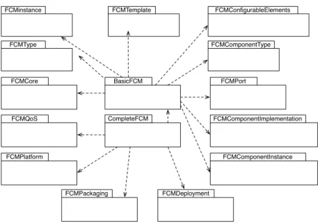
The FCM metamodel identifies two main packages: BasicFCM and CompleteFCM. The diagram of these two packages is depicted in Figure 1. Concepts in the BasicFCM package mainly address issues related to composition, and concepts in the CompleteFCM package address issues related to deployment.
The BasicFCM package defines the basic concepts associated with a FCM component. Many elements in our component model have a name. The FCM-Core sub-package defines a specific meta model element called NamedElement that reflects this: it is a common superclass for all model elements that have a name. In order to organize related elements, a common concept is to intro-duce name spaces, i.e. to package related elements. But not all elements can be owned directly by a package (e.g., attributes are owned by a component, as shown below). As for the named element, we introduce a superclass that captures the concept of elements that “can be packaged”. Please note that the package is itself a packageable element, enabling arbitrary nesting.
A component is an entity of encapsulation. It is characterized by (1) its name, (2) a set of well defined interaction points, called ports, (3) the set of configuration attributes that it owns and (4) its behavior. As said before, an important and quite common concept is the separation between a component
BasicFCM CompleteFCM FCMCore FCMType FCMinstance FCMTemplate FCMPort FCMComponentType FCMComponentImplementation FCMConfigurableElements FCMComponentInstance FCMQoS FCMPackaging FCMPlatform FCMDeployment
Figure 1: The FCM architecture
type and its implementation. The first three aspects define a component type which is specified in the package FCMComponentType (while relying on the spec-ification of ports and attributes within other packages). The fourth aspect is only relevant for a component implementation. In the sequel, we state which packages of the metamodel deal with component characteristics (2) to (4). (2) Ports (see FCMPort package) are a fundamental concept of component modeling. This common encapsulation mechanism exists in most component-oriented frameworks, even though the name and the semantics given to this concept may vary according to the framework. A major characteristic of ports in FCM is that they are not only characterized by a type, but also by a kind (PortKind). The kind carries an informally specified semantics and a rule that characterizes the port in terms of provided and required interfaces (mapping rule). This mechanism enables the extensibility of ports: instead of defining a specific metamodel element for each kind of port (e.g., a port that provides an interface, a port that consumes events, etc.), a single generic port is used. New port kinds can be defined in modeling library (i.e. without modifying the metamodel), along with a mapping rule for provided and required interfaces. Due to their role in the context of ports, interfaces are introduced as a set of operation signatures within FCM. They are actually the only concrete kind of “types” defined by the FCMType package which introduces the generic notion of a type and typed elements, i.e. elements such as ports that have a type. The metamodel remains voluntarily generic about what a type is, except for interfaces.
(3) The component type owns a set of configuration attributes. The basic idea is that an instance of a component (see below) fixes the value of such an attribute. The ability to have attributes is inherited via the superclass FCMConfigurableElement defined in the package FCMConfigurableElements. Besides the component type, other elements (notably port kinds) inherit from
this metamodel element or its variant ConfigurableElementInstance. (4) A component implementation (see package FCMComponentImplementation) is a realization of a component type. The implementation is either monolithic or described as an assembly of parts (i.e. some manifestation of component types or implementations assembled together). In case of the latter, an imple-mentation owns a set of Parts and a set of connectors that connect the ports of these parts. A connector has a type (see connector type above) and an imple-mentation (ConnectorImpleimple-mentation), which is a specification of a component implementation.
Connectors are a specific variant of components that are responsible for in-teractions. In the metamodel, a ConnectorType inherits from ComponentType without adding any particular properties. Likewise, a connector implementa-tion inherits from a component implementaimplementa-tion. This concept is important for extensibility: instead of having a pre-defined set of interaction mechanisms, a connector type describes interaction patterns, and a connector implementation is a possible realization of this pattern. A specific property of connectors is that their definition is not fixed since they need to adapt to the context in which they are used, e.g., a connector port may be typed with a placeholder type which is later replaced by concrete component type. This mechanisms is cap-tured with the FCMTemplate package. The idea is to be able to capture generic model elements (i.e. with explicit template parameters) that are representative of a particular application-domain and/or particular target technologies. These generic elements can then be made application specific by simple and systematic parameter bindings.
FCMInstance and FCMComponentInstance. The FCMInstance package in-troduces mechanisms for specifying statically (i.e. at design time) run-time instances. An instance specification has a set of slots which associate a model element with a value (ValueSpecification). These mechanisms are inspired by UML2. The FCMComponent instance package defines an extension of the generic instance specification in case of components, i.e. specific slots that reference contained parts, ports or connectors. For instance a PartSlot asso-ciates the parts of a component with a value that they have within a specific instance.
The CompleteFCM package defines extended features related to deployment associated with a FCM component in the following packages:
• FCMQoS. QoS definitions within the FCM are based on QoS aware types and QoS expression. A component implementation owns a set of QoS expressions. However, there is no concrete mechanism on how QoS ex-pressions are formed, since the QoS definition (non-functional aspects in general) should not make use of a particular formalism. This enables the use of existing means to define QoS properties. A mechanism which is intended to be used in conjunction with FCM is the UML profile MARTE which features a library with basic non-functional property (NFP) types and a value specification language (VSL).
• FCMPackaging. Packaging allows to bundle one or more implementations of the same component type within a single unit. The basic idea is to have a single artifact that represents a component in order to facilitate
compo-nent deployment and installation without fixing a certain technology how the contained parts are stored (e.g., in a ZIP file).
• FCMServices. This package offers the possibility to define so-called ser-vices that intercept interactions through a port (before and/or after an invocation). Similar to a connector, a service is an extension of a normal component, i.e. has a separation between type and implementation and can be defined in a model library. The latter implies that the set of ser-vices can be extended depending on domain needs. A service is typically realized within a container. However, the concept of a container is not part of FCM itself, since from a modeling viewpoint, it is sufficient to specify which services should be activated for a component instance. • FCMPlatform. A platform (FCM Domain) is characterized by a set of
elements that are either processing resources (Node) or communication resources (e.g., Bus). This concept can be extended as required for certain domains (e.g., to add specific communication resources).
• FCMDeployment. This package defines primarily the concept of a static allocation of component instances on nodes (Node). This information is captured by a DeploymentPlan (adopting CCM terminology) which owns a set of Deployments which associate instance and node.
4.3
Dimensions of Flexibility
As mentioned in Section 4.1, a major design criterion of the FCM meta-model has been to enable flexibility without a modification of the meta-model but with introducing model libraries. This section summarizes the four main flexibility dimensions which are achieved by the FCM.
• New component ports. New component ports enable the implementation of new interaction mechanisms. The ability to extend ports via the defi-nition of a port kind element within a model library is the first building block for flexible interactions and is enabled via the package FCMPort. • New connectors. The second flexibility dimension is provided by the
ability to define new interaction components along with their realization in a model library. As previously mentioned, connectors with the FCM are variants of components. They are thus specified as specialization of com-ponent types (package FCMType) and comcom-ponent implementations (pack-age FCMComponentImplementation).
• New non functional properties. The FCMQoS package does not assume a particular language for defining QoS expressions. This enables the use of languages or approaches tailored to a particular application domain as long as the definition of specific non functional properties.
• New containers. The FCMServices package allows the definition of new container services by means of a model library. Since services are com-ponents embedded into the container, there is also a separation between type and implementation.
Overall, the FCM metamodel provides a common ground for designing and implementing component-based systems where the concepts such as component, port, connector, can be specialized to match the specificities of runtime plat-forms. We illustrate this in the next section with three case studies on three different platforms: Fractal/Think, eC3M, and OASIS.
5
CASE STUDIES
This section illustrates the use of the Flex-eWare Component Model that has been presented in the previous section, on three use cases: wireless sensor net-works (Section 5.1), distributed client/server applications (Section 5.2), and control systems for electrical devices (Section 5.3). For each use case, the con-cepts defined in the FCM are mapped onto different technologies: the Frac-tal/Think component framework [20,21], the eC3M middleware and the OASIS tool chain [24].
This section covers a broad range of usages and technologies for embedded systems and wishes to demonstrate the adequacy of the FCM in all these cases. Furthermore, each use case emphasizes a particular aspect related to the design and implementation of embedded systems: respectively, reconfiguration, low memory footprint and software component reuse.
All three presentations follow the same pattern. We start by introducing briefly the case study and the platform, we present the mapping of FCM con-cepts onto the platform, we give an overview of the toolchain associated with the platform, we report on some experimental data, and we conclude by high-lighting the flexibility dimensions of the FCM that have been put into practice by the case study.
5.1
Case study 1: FCM over Fractal
Our first case study is in the domain of Wireless Sensor Networks (WSN). This domain is rather broad, going from city automation services (e.g. smart public lighting, waste management) to personal healthcare services (e.g. continual medical monitoring) and to Customer Premise Equipment (CPE). The target execution platform for this case study is the Fractal/Think [20,21] component framework which is a C implementation of the Fractal component model (see Section 3.2).
The Think compiler supports a set of flexible-oriented properties [35] for de-signing Reconfigurable Wireless Embedded Systems. These properties are used to configure the Think compilation process: First, to generate the meta-data allowing to reify the Fractal component concepts at runtime (e.g., to retrieve a component attribute or the descriptor of a bound interface). Second, to generate the standard Fractal controller implementations over these meta-data [36]. As dynamic reconfiguration may not be necessary for all system components, the Think framework provides fine-grained mechanisms to specify whether a simple component attribute, a single component or a subset of system components is not likely to evolve at execution time.
These features allow to generate minimal reconfiguration infrastructures, optimizing available resources usage in accordance with application domain
needs [37,38]. They are typical non-functional concerns which can be expressed by extension mechanisms provided within the FCM metamodel.
5.1.1 Mapping of FCM concepts.
We briefly outline below the mapping between FCM and Fractal. Readers may refer to [39] for further details.
Mapping of Generic FCM ADL Concepts. The mapping between FCM and Fractal ADL is straightforward since the latter is a building block for defining the FCM metamodel presented in Section 4. Therefore, most of the FCM concepts can be directly mapped towards Fractal model entities, apart from two features not handled by Fractal: i) A FCM model relies on three levels of architecture’s specification – type, implementation and instance – while Fractal ADL focuses on the latter level. Thereby, a FCM instance model is the only entry point of the mapping process between FCM and Fractal. ii) The concept of port is not supported by Fractal, where component interactions are only specified by a binding between a single required interface and a single provided interface. As the concept of FCM interface is isomorphic to the one of Fractal, the mapping rule merely consists in translating each FCM connector instance into a set of Fractal bindings, according to the set of required and provided interfaces attached to both FCM port ends.
Mapping of Reconfiguration Features. We rely on the extension mech-anism defined in the FCM and presented in Section 4 for specifying reconfigu-ration capabilities:
• Within the FCM model library, we define the set of services implemented by the Fractal reconfiguration controllers. The FCM developer then spec-ifies which component containers of its application must provide local reconfiguration capability at runtime.
• The flexible-oriented properties defined by Think are modeled at FCM level by means of QoSExpressions. These expressions can be attached to any FCM elements, and can be configured to be interpreted recursively by the Think compiler (e.g. for specifying with a single QoSExpression attached to a composite that it must be applied to all of its subcompo-nents).
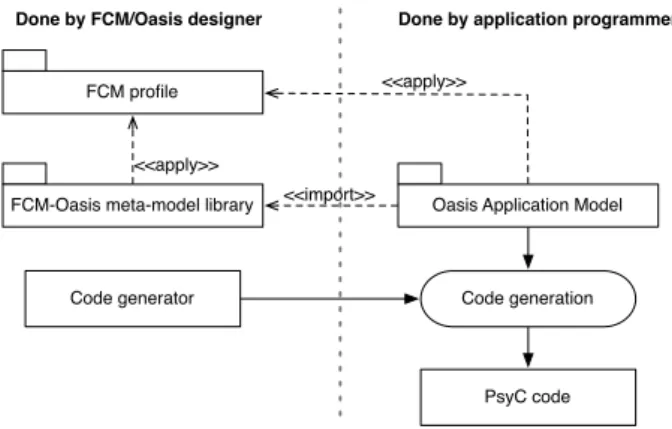
5.1.2 Overview of the Process and Associated Tools.
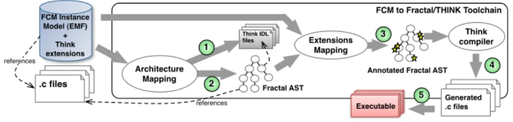
The mapping from an FCM instance model to a Think executable is sketched out in Figure2. The numbered steps correspond respectively to the following treatments:
1. For each FCM interface signature, a corresponding file is generated in the Think Interface Description Language (IDL).
2. The FCM architecture description is translated into Fractal AST nodes, which is the internal architectural representation used by the Think com-piler.
references Fractal AST FCM Instance Model (EMF) + Think extensions references
Annotated Fractal AST
2 Extensions Mapping 3 1 Architecture Mapping Executable Think compiler 4 FCM to Fractal/THINK Toolchain Think IDL files .c files .c files Generated .c files 5 .c files .c files .c files
Figure 2: FCM to Fractal/Think Process.
3. The flexibility-oriented properties set by the FCM developer as QoSEx-pressions are interpreted, and the corresponding fine-grained properties expected by the Think compiler are inferred in consequence. The same mechanism is used to set the Fractal containers specified at FCM level. This step outputs an annotated Fractal AST which feeds the compiler. 4. The Think compiler maps architectural elements to C variables in
imple-mentation code, transforms existing functional code and produces meta-data and Fractal controller implementations according to the annotations attached to the AST nodes. In addition, it generates the code implement-ing the bootstrap process of the system.
5. Finally, the set of C source files generated by Think are compiled and linked by a classical C compiler.
5.1.3 Experiments.
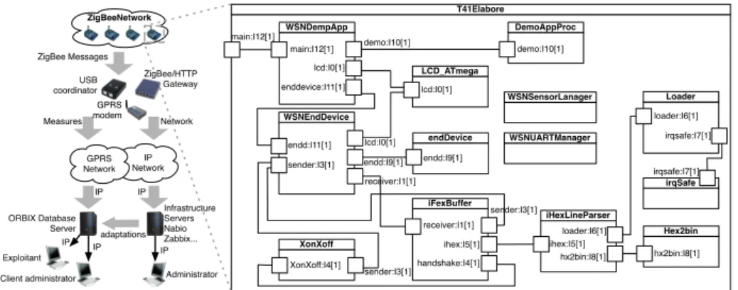
We designed a typical WSN infrastructure whose purpose is to monitor and manage a group of sensors and/or actuators deployed in the field (e.g. buildings, factories, forests). These devices form a Zigbee network which is administrated via an ADSL or GPRS Internet connection. Measured data are sent to an oBIX [40] server and are available for consultation via a web-based graphical interface. Additionally, administrators are able to remotely modify device architectures. Left side of Figure3shows a simplified version of our infrastructure.
Since we are interested in evaluating run-time reconfiguration capabilities in resource-limited systems, we focus on the Zigbee network devices which typically expose this kind of constraint. In our case study, the Zigbee network is mainly composed of AVRRAVEN boards including an Atmega1284p processor (8-bit AVR, 128KB of Flash memory, 16KB RAM, 4K EEPROM) and a Atmega3290 processor dedicated to LCD management. These devices are coordinated by a RZUSBSTICK board (90USB1287 8-bit processor) bound to the Zigbee/HTTP gateway. On each sensor node a FCM architecture is deployed, as illustrated in the right part of Figure 3. This architecture implements the required services to dynamically update or change its components sent in a binary form via the Zigbee network.
Dynamic Reconfiguration Experiment. One of the reconfiguration ex-amples we ran was motivated by the need for changing the way remote devices present data to in-site users through its embedded display. The goal is to re-place the LCD manager component LCD ATmega (see Figure3) by a new version
T41Elabore WSNDempApp main:I12[1] LCD_ATmega endDevice WSNEndDevice XonXoff DemoAppProc iFexBuffer iHexLineParser Hex2bin irqSafe Loader WSNSensorLanager WSNUARTManager demo:I10[1] lcd:I0[1] enddevice:I11[1] XonXoff:I4[1] ihex:I5[1] endd:I11[1] sender:I3[1] sender:I3[1] lcd:I0[1] endd:I9[1] demo:I10[1] lcd:I0[1] endd:I9[1] receiver:I1[1] receiver:I1[1] sender:I3[1] handshake:I4[1] ihex:I5[1] loader:I6[1] hx2bin:I8[1] hx2bin:I8[1] loader:I6[1] irqsafe:I7[1] irqsafe:I7[1] main:I12[1] ZigBee Messages ZigBeeNetwork USB coordinator ZigBee/HTTP Gateway GPRS modem IP Network GPRS Network ORBIX Database Server Infrastructure Servers Nabio Zabbix... Exploitant
Client administrator Administrator adaptations IP IP IP IP IP Network Measures
Figure 3: Global infrastructure and FCM architecture instance deployed on each sensor node.
of it, newLCD ATmega during system execution. To accomplish it, the following operations are executed:
1. The Zigbee Network Coordinator (ZNC) sends a pre-defined message to the device, which passes to a special Reconfiguration mode.
2. The ZNC sends the newLCD ATmega component to the device. This new component was previously converted into an Intel HEX format. Code and Data is sent through the network line-by-line.
3. Once the transmission is completed, a reference to a Fractal interface im-plemented by the container of newLCD ATmega and allowing its run-time introspection is retrieved by the WSNEndDevice component. This intro-spection service allows to retrieve the provided interfaces of the uploaded component.
4. The initial bindings to LCD ATmega are destroyed and replaced to bound its uploaded instance thanks to a Fractal controller implemented by the container of the WSNEndDevice component.
5. The device returns to a Nominal execution mode. In this particular case the device is rebooted. This could be avoided if component containers expose and implement the Fractal life-cycle controller which ensures a safe transition between Reconfiguration and Nominal modes. However, providing this service at runtime has a non-negligible impact in terms of memory footprint, which is the most critical performance issue for WSN applications, as discussed in the next section.
Low Resources Usage Experimental Results. Table 3 presents the memory footprint of a binary generated from the FCM model instance shown in Figure 3, intended to be deployed in a sensor node. We measure the overhead in code (i.e. .text section) and data, including initialized (i.e. .data section) and uninitialized (i.e. .bss section) data. We make this distinction as code is usually placed in ROM, whereas data are generally placed in RAM. Table3(a) presents the footprint of the application code compared with the code generated
by the Think framework. We consider three scenarios: i) If none of the FCM extensions presented in Section5.1.1are used to explicitly specify the reconfig-uration points of the architecture, Think generates by default meta-data and Fractal controllers for the whole system (Table3(b)). ii) In the second scenario, the Think meta-data are generated for the whole system but only the mandatory Fractal controllers are deployed to implement the reconfiguration scenario with the newLCD ATmega component presented above (Table3(c)). iii) Finally, only the mandatory Fractal controllers and meta-data are deployed (Table3(d)).
These results show that a fine-grained tuning of the architecture reconfigura-tion points is a required feature to fulfill the constraints of Wireless Embedded Systems. By the use of FCM extensions, we provide to the developer high-level mechanisms to explicitly deploy only the mandatory services required by a reconfiguration scenario. The induced overheads are then paid only where necessary.
5.1.4 Flexibility Dimensions.
This case study puts into practice two of the four flexibility dimensions iden-tified in Section4.3, and their associated model libraries: container and non functional properties, reifying at model level the specificities of the Think runtime platform. The container dimension enables dealing with the recon-figuration controllers. The set of reconrecon-figuration services supported by Think has been therefore defined as an FCM model library directly usable within the end-user’s specifications. The non functional properties dimension concerns the QoSExpressions for Think flexibility-oriented properties. This extension mecha-nism provided by FCM offers a straightforward mean to decorate model artifacts with annotations. These annotations are in turn used to drive the interpretation process leading to the generation of Think executables.
5.2
Case study 2: FCM over eC3M
The second case study is in the domain of distributed client/server applications with the eC3M middleware platform presented in Section 3.1.
5.2.1 Mapping of FCM concepts.
Since eC3M is directly based on the FCM profile, no mapping is required. Read-ers may refer to [39] for further details. Application models typically contain additional information in form of MARTE stereotypes, in order to specify real-time aspects. An example is the real-real-time feature of the MARTE “High-Level Application Modeling” (HLAM) section, shown in Section 3.1. In general, the MARTE value specification language and the standardized NFP library (Annex D of the MARTE specifications) is used to specify non-functional parameters, notably durations (NFP duration).
5.2.2 Overview of the Process and Associated Tools.
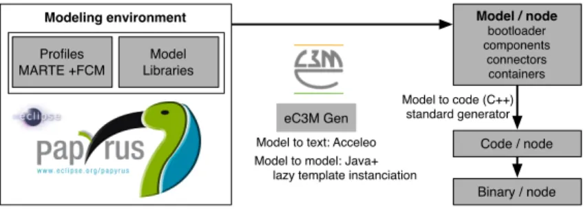
An overview of the eC3M toolchain is provided in Figure 4. The main spec-ification artifact is a UML model enriched by information from the profiles FCM and MARTE. A set of model transformations is executed to transform
Model / node bootloader components connectors containers Code / node Binary / node Modeling environment Profiles MARTE +FCM Model Libraries Model to code (C++) standard generator Model to text: Acceleo
Model to model: Java+ lazy template instanciation
eC3M Gen
Figure 4: The eC3M toolchain
the component-based model into an object-oriented model on which standard UML to code generators, in particular UML to C++ generators can be applied.
These transformations include:
• The reification of connectors, i.e. replacing FCM connectors (stereotyped UML connectors) with interaction components that are adapted to the application context, i.e., use port types that are compatible with those of the application components (and implementations adapted to these port types as well).
• The implementation of the container pattern, i.e. redirecting connections to an application component with connections to the container which em-beds the application component.
• Apply standard design patterns that transform components into standard classes, i.e. replace ports with functions related to manipulate connections and obtain references. This function is a bit similar to CCM IDL3 towards IDL2 mapping.
• Create a subset of the model per node on which an application is deployed. Each of these models contains a bootloader that is responsible for instan-tiating the components that are deployed on this node (in the context of a static deployment).
5.2.3 Experiments.
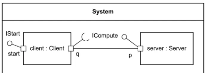
The eC3M model has so far been used for some sample applications, including a data acquisition system. In the sequel, we examine a very simple system consisting of a client and a server component, as shown in Fig.5 (the interface ICompute consists of two operations, add and mult ). In order to start initial activities, eC3M uses a simple convention: the client owns a port providing the standard eC3M interface called IStart. This interface includes the operation run (similar to the Java Runnable interface) which is automatically invoked during the system start-up.
The client can use the “standard” FCM port kind UseInterface resulting in a derived required interface which corresponds exactly to the interface which types the port – in this case ICompute. In real-time applications, the caller may want to pass for instance a period length (in order to enable automatic cyclic invocations) and a relative deadline along with the operation invocation.