Science Arts & Métiers (SAM)
is an open access repository that collects the work of Arts et Métiers Institute of
Technology researchers and makes it freely available over the web where possible.
This is an author-deposited version published in: https://sam.ensam.eu Handle ID: .http://hdl.handle.net/10985/15637
To cite this version :
Iheb CHERIF, José OUTEIRO, Dominique COTTON, Gérard POULACHON, Guillaume
CHARRONDIERE, Alexandre BROSSE - Effects of toolpath and clamping strategies in machining distortion of stainless-steel parts - In: 17th CIRP Conference on Modeling of Machining
Operations, Royaume-Uni, 2019-06-13 - Procedia CIRP - 2019
Any correspondence concerning this service should be sent to the repository Administrator : archiveouverte@ensam.eu
ScienceDirect
Available online at www.sciencedirect.com Available online at www.sciencedirect.com
ScienceDirect
Procedia CIRP 00 (2017) 000–000
www.elsevier.com/locate/procedia
2212-8271 © 2017 The Authors. Published by Elsevier B.V.
Peer-review under responsibility of the scientific committee of the 28th CIRP Design Conference 2018.
28th CIRP Design Conference, May 2018, Nantes, France
A new methodology to analyze the functional and physical architecture of
existing products for an assembly oriented product family identification
Paul Stief *, Jean-Yves Dantan, Alain Etienne, Ali Siadat
École Nationale Supérieure d’Arts et Métiers, Arts et Métiers ParisTech, LCFC EA 4495, 4 Rue Augustin Fresnel, Metz 57078, France * Corresponding author. Tel.: +33 3 87 37 54 30; E-mail address: paul.stief@ensam.eu
Abstract
In today’s business environment, the trend towards more product variety and customization is unbroken. Due to this development, the need of agile and reconfigurable production systems emerged to cope with various products and product families. To design and optimize production systems as well as to choose the optimal product matches, product analysis methods are needed. Indeed, most of the known methods aim to analyze a product or one product family on the physical level. Different product families, however, may differ largely in terms of the number and nature of components. This fact impedes an efficient comparison and choice of appropriate product family combinations for the production system. A new methodology is proposed to analyze existing products in view of their functional and physical architecture. The aim is to cluster these products in new assembly oriented product families for the optimization of existing assembly lines and the creation of future reconfigurable assembly systems. Based on Datum Flow Chain, the physical structure of the products is analyzed. Functional subassemblies are identified, and a functional analysis is performed. Moreover, a hybrid functional and physical architecture graph (HyFPAG) is the output which depicts the similarity between product families by providing design support to both, production system planners and product designers. An illustrative example of a nail-clipper is used to explain the proposed methodology. An industrial case study on two product families of steering columns of thyssenkrupp Presta France is then carried out to give a first industrial evaluation of the proposed approach.
© 2017 The Authors. Published by Elsevier B.V.
Peer-review under responsibility of the scientific committee of the 28th CIRP Design Conference 2018. Keywords: Assembly; Design method; Family identification
1. Introduction
Due to the fast development in the domain of communication and an ongoing trend of digitization and digitalization, manufacturing enterprises are facing important challenges in today’s market environments: a continuing tendency towards reduction of product development times and shortened product lifecycles. In addition, there is an increasing demand of customization, being at the same time in a global competition with competitors all over the world. This trend, which is inducing the development from macro to micro markets, results in diminished lot sizes due to augmenting product varieties (high-volume to low-volume production) [1]. To cope with this augmenting variety as well as to be able to identify possible optimization potentials in the existing production system, it is important to have a precise knowledge
of the product range and characteristics manufactured and/or assembled in this system. In this context, the main challenge in modelling and analysis is now not only to cope with single products, a limited product range or existing product families, but also to be able to analyze and to compare products to define new product families. It can be observed that classical existing product families are regrouped in function of clients or features. However, assembly oriented product families are hardly to find.
On the product family level, products differ mainly in two main characteristics: (i) the number of components and (ii) the type of components (e.g. mechanical, electrical, electronical).
Classical methodologies considering mainly single products or solitary, already existing product families analyze the product structure on a physical level (components level) which causes difficulties regarding an efficient definition and comparison of different product families. Addressing this
Procedia CIRP 82 (2019) 427–431
2212-8271 © 2019 The Authors. Published by Elsevier B.V.
Peer-review under responsibility of the scientific committee of The 17th CIRP Conference on Modelling of Machining Operations 10.1016/j.procir.2019.04.065
ScienceDirect
Procedia CIRP 00 (2019) 000–000 www.elsevier.com/locate/procedia2212-8271 © 2019 The Authors. Published by Elsevier B.V.
Peer-review under responsibility of the scientific committee of The 17th CIRP Conference on Modelling of Machining Operations, in the person of the Conference Chair Dr Erdem Ozturk and Co-chairs Dr Tom Mcleay and Dr Rachid Msaoubi.
17th CIRP Conference on Modelling of Machining Operations
Effects of toolpath and clamping strategies in machining distortion of
stainless-steel parts
Iheb Cherif
a,*, José Outeiro
a, Dominique Cotton
a, Gérard Poulachon
a, Guillaume Charrondiere
a,
Alexandre Brosse
baArts et Metiers ParisTech, LaBoMaP , UBFC, Cluny 71250, France bFRAMATOME, 10 rue Juliette Récamier, 69456 Lyon cedex 06, France
* Corresponding author. Tel.: +33-385-595-388; fax: +33-385-595-388. E-mail address: iheb.cherif@ensam.eu
Abstract
Heat exchangers in new nuclear power generation plants are made of thin AISI 316L stainless-steel plates stacked together in order to improve their efficiency and compactness. To ensure the assembly, the global distortion of those plates must be mastered and minimized, mainly by predicting the evolution of the residual stress field during their manufacturing process chain. During machining, those residual stresses are redistributed to reach another equilibrium state, leading to a macroscopic part distortion. The main objective of this work is to study experimentally the influence of the machining toolpath and clamping strategies on the global part distortion. Then, a part distortion model is developed in order to verify the clamping effect on the distortion.
© 2019 The Authors. Published by Elsevier B.V.
Peer-review under responsibility of the scientific committee of The 17th CIRP Conference on Modelling of Machining Operations, in the person of the Conference Chair Dr Erdem Ozturk and Co-chairs Dr Tom Mcleay and Dr Rachid Msaoubi.
Keywords: Machining; Tool path; Clamping
1. Introduction
Compactness and efficiency are the major advantages of the future generation of reactors [1]. In fact, nuclear heat exchangers in these reactors include thin plates made in AISI 316L austenitic stainless-steel.
At the last step of the manufacturing process, the plates are grooved by milling operation. Residual stresses are then redistributed [2,3], and new stresses are introduced in the material [4,5], inducing part distortion.
There are numerous factors that can influence this distortion. These factors had already been studied by many authors. Liu et al. [6], using the layer removal method coupled with numerical simulations, put in evidence a material removal rate threshold, beyond which the distortion stabilizes. They concluded that the first passes induce the main distortion and they considered that after 60% of removed material, part distortion becomes stable.
Outeiro et al. [7] studied the influence of the cutting parameters on the residual stresses induced by turning AISI 316L. They observed tensile residual stresses at the machined surface for all the cutting conditions. These stresses increased with feed and decreased with the depth of cut. According to Richter-Trummer et al. [8], the residual stresses generated by high speed machining does not affect part distortion due to the high spindle rotation speed and feed rates.
Hassini [9] and Cerutti [10] studied the influence of clamping strategies on part distortion. They showed that the number of clamps had a negligible influence on the global distortion but had an impact on dimensional tolerances. Their conclusions are similar regarding to the influence of toolpath strategy.
In the present paper, effects of toolpath and clamping strategies on part distortion were analyzed experimentally, then a numerical simulation was made. The model of distortion was developed considering only the clamping force. This model Available online at www.sciencedirect.com
ScienceDirect
Procedia CIRP 00 (2019) 000–000
www.elsevier.com/locate/procedia
2212-8271 © 2019 The Authors. Published by Elsevier B.V.
Peer-review under responsibility of the scientific committee of The 17th CIRP Conference on Modelling of Machining Operations, in the person of the Conference Chair Dr Erdem Ozturk and Co-chairs Dr Tom Mcleay and Dr Rachid Msaoubi.
17th CIRP Conference on Modelling of Machining Operations
Effects of toolpath and clamping strategies in machining distortion of
stainless-steel parts
Iheb Cherif
a,*, José Outeiro
a, Dominique Cotton
a, Gérard Poulachon
a, Guillaume Charrondiere
a,
Alexandre Brosse
baArts et Metiers ParisTech, LaBoMaP , UBFC, Cluny 71250, France bFRAMATOME, 10 rue Juliette Récamier, 69456 Lyon cedex 06, France
* Corresponding author. Tel.: +33-385-595-388; fax: +33-385-595-388. E-mail address: iheb.cherif@ensam.eu
Abstract
Heat exchangers in new nuclear power generation plants are made of thin AISI 316L stainless-steel plates stacked together in order to improve their efficiency and compactness. To ensure the assembly, the global distortion of those plates must be mastered and minimized, mainly by predicting the evolution of the residual stress field during their manufacturing process chain. During machining, those residual stresses are redistributed to reach another equilibrium state, leading to a macroscopic part distortion. The main objective of this work is to study experimentally the influence of the machining toolpath and clamping strategies on the global part distortion. Then, a part distortion model is developed in order to verify the clamping effect on the distortion.
© 2019 The Authors. Published by Elsevier B.V.
Peer-review under responsibility of the scientific committee of The 17th CIRP Conference on Modelling of Machining Operations, in the person of the Conference Chair Dr Erdem Ozturk and Co-chairs Dr Tom Mcleay and Dr Rachid Msaoubi.
Keywords: Machining; Tool path; Clamping
1. Introduction
Compactness and efficiency are the major advantages of the future generation of reactors [1]. In fact, nuclear heat exchangers in these reactors include thin plates made in AISI 316L austenitic stainless-steel.
At the last step of the manufacturing process, the plates are grooved by milling operation. Residual stresses are then redistributed [2,3], and new stresses are introduced in the material [4,5], inducing part distortion.
There are numerous factors that can influence this distortion. These factors had already been studied by many authors. Liu et al. [6], using the layer removal method coupled with numerical simulations, put in evidence a material removal rate threshold, beyond which the distortion stabilizes. They concluded that the first passes induce the main distortion and they considered that after 60% of removed material, part distortion becomes stable.
Outeiro et al. [7] studied the influence of the cutting parameters on the residual stresses induced by turning AISI 316L. They observed tensile residual stresses at the machined surface for all the cutting conditions. These stresses increased with feed and decreased with the depth of cut. According to Richter-Trummer et al. [8], the residual stresses generated by high speed machining does not affect part distortion due to the high spindle rotation speed and feed rates.
Hassini [9] and Cerutti [10] studied the influence of clamping strategies on part distortion. They showed that the number of clamps had a negligible influence on the global distortion but had an impact on dimensional tolerances. Their conclusions are similar regarding to the influence of toolpath strategy.
In the present paper, effects of toolpath and clamping strategies on part distortion were analyzed experimentally, then a numerical simulation was made. The model of distortion was developed considering only the clamping force. This model © 2019 The Authors. Published by Elsevier B.V.
428 Iheb Cherif et al. / Procedia CIRP 82 (2019) 427–431
Author name / Procedia CIRP 00 (2019) 000–000 3 unclamping. The positioning as well as the measurement
program are the same for all parts.
To ensure the repeatability of the experiments, three parts were machined in similar conditions. The distortion profile is studied in a plane (XZ) located at Y = 100 mm (Fig. 1). The average flatness defect is 0.174 ± 0.009 mm. Therefore, tests repeatability was being verified, so each test presented in
Table 1 was made once.
The temperature measurements have been carried out in order to ensure that the measured values by the load washers are only caused by the residual stress redistribution within the part and not due to the expansion of the clamping system components. The part as well as two clamping screws have been instrumented with K-type thermocouples. A 2 °C increase in temperature is observed into the part leading to a thermal expansion of 0.7 µm across the part thickness. However, this dimensional variation can be neglected due to the acquisition system resetting.
4. Part distortion model
A 3D model of part distortion was developed and simulated using SYSWELD, a commercial finite element analysis software. First, a predefined residual stress state is used in the model as input data. This initial distribution is obtained after residual stresses measurements in the part before machining. These residual stresses are determined experimentally using both layer removal and neutron diffraction techniques.
One of the aims of the part distortion model is to verify the presence of a local disturbance of the residual stress distribution. In this work, the FE-model considers the clamping/unclamping conditions only. In fact, the finite elements were removed in one step without considering the depth of cut neither the toolpath effects. Then, a second step is applied in order to find a new equilibrium state after removing the clamping forces (unclamping).
The initial clamping loading is applied as a pressure in Z direction. This loading is applied on the 2D elements which define the screw contact as shown in Fig. 3. The nodes of these 2D elements are free along X and Y directions.The model was defined using 113920 hexahedral elements. The width of each element varies between 1.8 and 4 mm, the length and the depth are respectively fixed to 5 and 0.25 mm. The contact between the part and the dynamometer is defined without friction. In order to simplify the numerical model, the dynamometer has been modelized as mechanical boundary conditions in specific nodes (under the part). An isotropic hardening plasticity model is used in this simulation.
Fig. 3. Mesh and position of pressure application 5. Results and discussion
5.1. Influence of the initial clamping force
Three levels of initial force have been tested (5, 10 and 20 kN/screw). The experimental distortion profiles are presented in Fig. 4. These distortion profiles are represented by the variation of the Z dimension along the x-axis.
Fig. 4. Part distortion induced by the initial clamping (Tests #1, #2 and #3). The distortion profile is similar for an initial clamping force of 5 or 10 kN/screw. By increasing it up to 20 kN/screw, the global distortion is lower than the ones for the other clamping forces. The clamping forces create a stress field into the part which superimposes to the residual stresses field. While machining, the residual stresses are reorganized, and the superposition of both stress fields can affect the distortion. This hypothesis should be confirmed by the numerical simulations of part distortion.
5.2. Influence of the axial depth of cut
As shown in Fig. 5, the axial depth of cut has a great influence on the global distortion. This could be explained by the residual stress distribution into the part. This one has been determined by X-ray and neutron diffraction techniques. The obtained in-depth residual stress profile in both X and Y directions (through the part thickness) shows a compression layer is 0.5 mm. Between 0.5 mm and 2 mm, the stress is slightly positive. When removing a 1-mm layer, the tensile-compressive ratio in this layer is unbalanced, leading to a great distortion. In contrast, the ratio is more balanced when removing a 3-mm layer, causing less part distortion after machining.
0 20 40 60 80 100 120 140 160 0.00 0.02 0.04 0.06 0.08 0.10 0.12 0.14 Z L M R Z [m m] X [mm] Fi C.screw = 5 kN Fi C.screw = 10 kN Fi C.screw = 20 kN Toolpath: LMR ap= 1 mm Y = 100 mm : 2D elements which define the screw contact : Pression in Z direction
Y X Z 2 Author name / Procedia CIRP 00 (2019) 000–000
does not consider the sequence effect of various machining stages. Actually, the toolpath strategy and depth of cut are not included in this present model.
Nomenclature
Vc Cutting speed [m/min]
ae Radial depth of cut [mm]
ap Axial depth of cut [mm]
fz Feed per tooth [mm/rev/tooth]
FC. screwi Initial clamping force per screw [N]
FC. screwf Final clamping force per screw [N]
2. Experimental methodology
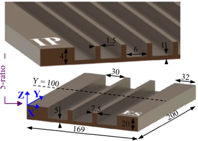
The geometry of samples after grooving operation was defined by applying a 5-ratio homothetic transformation on the dimensions of industrial parts. Fig. 1 shows the comparison between industrial parts (IP) and experimental samples (ES). All samples are extracted from a large plate and they are sufficiently far from the border, thus, it is assumed that all workpieces (ES) had the same initial distribution of residual stress.
Fig. 1. Geometry of industrial part (IP) and experimental sample (ES) in millimeters.
This work focuses on the influence of the clamping system and machining strategies on part distortion. The influence of cutting conditions such as the cutting speed Vc, radial depth of cut ae or cutting fluid (central emulsion) have not studied, thus they were kept constant for all machining tests. Preliminary tests were performed according to the tool-workpiece pair standard (NF E66-520) to determine the cutting parameters values and to ensure the cutting stability. Table 1 summarizes the tests and corresponding conditions that are applied experimentally.
Table 1. Test plan.
Test Toolpath fz [mm/rev/tooth] ap [mm] FC. screwi [kN] Vc [m/min] ae [mm] Influence of initial clamping force #1 LMR 0.12 1 5 130 30 #2 LMR 0.12 1 10 130 30 #3 LMR 0.12 1 20 130 30 Influence of depth of cut #2 #4 LMR LMR 0.12 0.03 1 3 10 10 130 130 30 30 Influence of toolpath #2 #5 LMR MLR 0.12 0.12 1 1 10 10 130 130 30 30 L, M and R represent the designation of the grooves (Left, Middle, Right), the order corresponding to the machining order.
3. Experimental set-up
End milling operation was performed over parallelepipedal samples of 200×169×20 mm. During machining, the parts are located and maintained by an isostatic instrumented clamping system [11,12]. Fig. 2 shows the various components of this system. Different force sensors are used: the 9255A piezoelectric Kistler dynamometer measured the forces generated during machining in the three spatial directions. The cutting force is determined, which was used to control the tool wear. It means that to avoid it, the cutting force should not exceed a given threshold. Kistler load washers (presented in
Fig. 2 by 1L, 1R, 2L, 2R, 3L and 3R) measured the instantaneous clamping force in each screw. These values give information about the part behavior during and after machining. The measurement error of load washers was determined during their calibration. This error depends on the range of the applied forces, which in this case is 0.54%. To overcome the drift signal issue, an acquisition reset is made every cutting path (for fz = 0.03 mm/rev/tooth) or every five passes (for fz = 0.12 mm/rev/tooth), and the force gain or loss is determinate. This permitted to reduce the signal drift.
Fig. 2. Instrumented clamping device on a CNC milling center. The geometrical control of parts is done with a DEA Coordinate Measuring Machine (CMM). The measurement uncertainty is 1.6 µm. Each part is measured in three different steps: i) before machining without clamping; ii) after machining, before unclamping; and iii) after machining and 20 5 1 4 1.5 6 5-rat io
Y
X
Z
Fastening part K-typethermocouple Dynamometric platform Kistler 9255A Sample Load washer Kistler 9102A
1L 1R
2R 2L
3R 3L
unclamping. The positioning as well as the measurement program are the same for all parts.
To ensure the repeatability of the experiments, three parts were machined in similar conditions. The distortion profile is studied in a plane (XZ) located at Y = 100 mm (Fig. 1). The average flatness defect is 0.174 ± 0.009 mm. Therefore, tests repeatability was being verified, so each test presented in
Table 1 was made once.
The temperature measurements have been carried out in order to ensure that the measured values by the load washers are only caused by the residual stress redistribution within the part and not due to the expansion of the clamping system components. The part as well as two clamping screws have been instrumented with K-type thermocouples. A 2 °C increase in temperature is observed into the part leading to a thermal expansion of 0.7 µm across the part thickness. However, this dimensional variation can be neglected due to the acquisition system resetting.
4. Part distortion model
A 3D model of part distortion was developed and simulated using SYSWELD, a commercial finite element analysis software. First, a predefined residual stress state is used in the model as input data. This initial distribution is obtained after residual stresses measurements in the part before machining. These residual stresses are determined experimentally using both layer removal and neutron diffraction techniques.
One of the aims of the part distortion model is to verify the presence of a local disturbance of the residual stress distribution. In this work, the FE-model considers the clamping/unclamping conditions only. In fact, the finite elements were removed in one step without considering the depth of cut neither the toolpath effects. Then, a second step is applied in order to find a new equilibrium state after removing the clamping forces (unclamping).
The initial clamping loading is applied as a pressure in Z direction. This loading is applied on the 2D elements which define the screw contact as shown in Fig. 3. The nodes of these 2D elements are free along X and Y directions.The model was defined using 113920 hexahedral elements. The width of each element varies between 1.8 and 4 mm, the length and the depth are respectively fixed to 5 and 0.25 mm. The contact between the part and the dynamometer is defined without friction. In order to simplify the numerical model, the dynamometer has been modelized as mechanical boundary conditions in specific nodes (under the part). An isotropic hardening plasticity model is used in this simulation.
Fig. 3. Mesh and position of pressure application 5. Results and discussion
5.1. Influence of the initial clamping force
Three levels of initial force have been tested (5, 10 and 20 kN/screw). The experimental distortion profiles are presented in Fig. 4. These distortion profiles are represented by the variation of the Z dimension along the x-axis.
Fig. 4. Part distortion induced by the initial clamping (Tests #1, #2 and #3). The distortion profile is similar for an initial clamping force of 5 or 10 kN/screw. By increasing it up to 20 kN/screw, the global distortion is lower than the ones for the other clamping forces. The clamping forces create a stress field into the part which superimposes to the residual stresses field. While machining, the residual stresses are reorganized, and the superposition of both stress fields can affect the distortion. This hypothesis should be confirmed by the numerical simulations of part distortion.
5.2. Influence of the axial depth of cut
As shown in Fig. 5, the axial depth of cut has a great influence on the global distortion. This could be explained by the residual stress distribution into the part. This one has been determined by X-ray and neutron diffraction techniques. The obtained in-depth residual stress profile in both X and Y directions (through the part thickness) shows a compression layer is 0.5 mm. Between 0.5 mm and 2 mm, the stress is slightly positive. When removing a 1-mm layer, the tensile-compressive ratio in this layer is unbalanced, leading to a great distortion. In contrast, the ratio is more balanced when removing a 3-mm layer, causing less part distortion after machining.
0 20 40 60 80 100 120 140 160 0.00 0.02 0.04 0.06 0.08 0.10 0.12 0.14 Z L M R Z [m m] X [mm] Fi C.screw = 5 kN Fi C.screw = 10 kN Fi C.screw = 20 kN Toolpath: LMR ap= 1 mm Y = 100 mm : 2D elements which define the screw contact : Pression in Z direction
Y X Z
does not consider the sequence effect of various machining stages. Actually, the toolpath strategy and depth of cut are not included in this present model.
Nomenclature
Vc Cutting speed [m/min]
ae Radial depth of cut [mm]
ap Axial depth of cut [mm]
fz Feed per tooth [mm/rev/tooth]
FC. screwi Initial clamping force per screw [N]
FC. screwf Final clamping force per screw [N]
2. Experimental methodology
The geometry of samples after grooving operation was defined by applying a 5-ratio homothetic transformation on the dimensions of industrial parts. Fig. 1 shows the comparison between industrial parts (IP) and experimental samples (ES). All samples are extracted from a large plate and they are sufficiently far from the border, thus, it is assumed that all workpieces (ES) had the same initial distribution of residual stress.
Fig. 1. Geometry of industrial part (IP) and experimental sample (ES) in millimeters.
This work focuses on the influence of the clamping system and machining strategies on part distortion. The influence of cutting conditions such as the cutting speed Vc, radial depth of cut ae or cutting fluid (central emulsion) have not studied, thus they were kept constant for all machining tests. Preliminary tests were performed according to the tool-workpiece pair standard (NF E66-520) to determine the cutting parameters values and to ensure the cutting stability. Table 1 summarizes the tests and corresponding conditions that are applied experimentally.
Table 1. Test plan.
Test Toolpath fz [mm/rev/tooth] ap [mm] FC. screwi [kN] Vc [m/min] ae [mm] Influence of initial clamping force #1 LMR 0.12 1 5 130 30 #2 LMR 0.12 1 10 130 30 #3 LMR 0.12 1 20 130 30 Influence of depth of cut #2 #4 LMR LMR 0.12 0.03 1 3 10 10 130 130 30 30 Influence of toolpath #2 #5 LMR MLR 0.12 0.12 1 1 10 10 130 130 30 30 L, M and R represent the designation of the grooves (Left, Middle, Right), the order corresponding to the machining order.
3. Experimental set-up
End milling operation was performed over parallelepipedal samples of 200×169×20 mm. During machining, the parts are located and maintained by an isostatic instrumented clamping system [11,12]. Fig. 2 shows the various components of this system. Different force sensors are used: the 9255A piezoelectric Kistler dynamometer measured the forces generated during machining in the three spatial directions. The cutting force is determined, which was used to control the tool wear. It means that to avoid it, the cutting force should not exceed a given threshold. Kistler load washers (presented in
Fig. 2 by 1L, 1R, 2L, 2R, 3L and 3R) measured the instantaneous clamping force in each screw. These values give information about the part behavior during and after machining. The measurement error of load washers was determined during their calibration. This error depends on the range of the applied forces, which in this case is 0.54%. To overcome the drift signal issue, an acquisition reset is made every cutting path (for fz = 0.03 mm/rev/tooth) or every five passes (for fz = 0.12 mm/rev/tooth), and the force gain or loss is determinate. This permitted to reduce the signal drift.
Fig. 2. Instrumented clamping device on a CNC milling center. The geometrical control of parts is done with a DEA Coordinate Measuring Machine (CMM). The measurement uncertainty is 1.6 µm. Each part is measured in three different steps: i) before machining without clamping; ii) after machining, before unclamping; and iii) after machining and 20 5 1 4 1.5 6 5-rat io
Y
X
Z
Fastening part K-typethermocouple Dynamometric platform Kistler 9255A Sample Load washer Kistler 9102A
1L 1R
2R 2L
3R 3L
430 Iheb Cherif et al. / Procedia CIRP 82 (2019) 427–431
Author name / Procedia CIRP 00 (2019) 000–000 5 As shown in Fig. 9, the simulation highlights a local residual
stress distribution different to the remaining part induced by the action of the clamping system.
Fig. 9. Residual stress distribution in Z direction after unclamping (display scale of distortion multiplied by 200)
6. Conclusion
This work shows the influence of the axial depth of cut, the machining toolpath and the initial clamping force on part distortion. Experimental tests highlight the great influence of the clamping system and machining strategy on the global part distortion. Using strong clamping forces and a large axial depth of cut allow to reduce it significantly. Contrary to Hassine [9]
and Cerutti [10],toolpath strategy also seems to influence the part behavior and the residual stresses redistribution. An asymmetric strategy increases part distortion and unbalances the residual stress redistribution.
The clamping system generates a local residual stress distribution different for the remaining parts of the sample. The part distortion model should be improved in future work. The sequence effect and the residual stresses generated by machining will be integrated to accurately predict part distortions. This future model will be determinant to understand the experimental conclusions and to validate the different hypothesizes presented in this paper.
Acknowledgements
This research was supported by the Burgundy regional council of Bourgogne-Franche-Comte through the Regional Action Plan for Innovation and the European Union. The authors would like to thank FRAMATOME for its financial and organizational support.
References
[1] Xiuqing L, Le Pierres R, Dewson SJ, Heat Exchangers for the Next Generation of Nuclear Reactors, vol. 39. United States: American Nuclear Society - ANS, 2006.
[2] Werke M, Wretland A, Ottosson P, Holmberg J, Machens M, Semere D, Geometric distortion analysis using a combination of the contour method and machining simulation, Procedia CIRP, 2018, vol. 72, pp. 1481–1486.
[3] Liu L, Sun J, Chen W, Zhang J, Finite element analysis of machining processes of turbine disk of Inconel 718 high-temperature wrought alloy based on the theorem of minimum potential energy, The International Journal of Advanced Manufacturing Technology, 2017, vol. 88, no. 9–12, pp. 3357–3369.
[4] Outeiro JC, Umbrello D, M’Saoubi R, Experimental and numerical modelling of the residual stresses induced in orthogonal cutting of AISI
316L steel, International Journal of Machine Tools and Manufacture, 2006, vol. 46, no. 14, pp. 1786–1794.
[5] Totten GE, Handbook of Residual Stress and Deformation of Steel. ASM International, 2002.
[6] Liu L, Sun J, Chen W, Sun P, Study on the machining distortion of aluminum alloy parts induced by forging residual stresses, Proceedings of the Institution of Mechanical Engineers, Part B: Journal of Engineering Manufacture, 2017, vol. 231, no. 4, pp. 618–627. [7] Outeiro JC, Dias AM, Lebrun JL, Astakhov VP, Machining Residual
Stresses in Aisi 316l Steel and Their Correlation with the Cutting Parameters, Machining Science and Technology, 2002, vol. 6, no. 2, pp. 251–270.
[8] Richter-Trummer V, Koch D, Witte A, dos Santos JF, de Castro PMST, Methodology for prediction of distortion of workpieces manufactured by high speed machining based on an accurate through-the-thickness residual stress determination, The International Journal of Advanced Manufacturing Technology, 2013, vol. 68, no. 9, pp. 2271–2281. [9] Hassini S, Multi-criteria qualification of machining sequence :
application to aerospace structural parts made from Airware® alloy, PhD Thesis, Université Blaise Pascal - Clermont-Ferrand II, 2015. [10] Cerutti X, Numerical modelling and mechanical analysis of the
machining of large aeronautical parts : Machining quality improvement, PhD Thesis, Ecole Nationale Supérieure des Mines de Paris, 2014.
[11] Mannan MA, Sollie JP, A Force-Controlled Clamping Element for intelligent Fixturing, CIRP Annals, 1997, vol. 46, no. 1, pp. 265–268. [12] Boerma JR, Kals HJJ, Fixture Design with FIXES: the Automatic
Selection of Positioning, Clamping and Support Features for Prismatic Parts, CIRP Annals, 1989, vol. 38, no. 1, pp. 399–402.
Y X Z 4 Author name / Procedia CIRP 00 (2019) 000–000
Fig. 5. Part distortion induced by the axial depth of cut (Tests #2 and #4). The experimental tests also showed that the axial depth of cut has a great influence on the called sequence effect. This effect is shown in Fig. 6 and described as follows. Since part is deforming during machining, the stiffeners sides progressively lose their parallelism and some areas are machined at several passes.
Fig. 6. Map of the dimension of the left grooves after unclamping (test #2 and test #4)
5.3. Influence of the toolpath strategy
Fig. 7 shows that toolpath has a great influence on the distortion profile. This observation is in contradiction with the ones of Hassini [9] and Cerutti [10]. The asymmetry induced by the LMR strategy leads to a greater distortion than the one generated by the MLR strategy.
Fig. 7. Distortion according to toolpath strategy (Test #2 and #5). Load washers highlight a heterogeneity of residual stresses redistribution, while using the asymmetric strategy LMR. As shown in Table 2, the increase of clamping force between the beginning and the end of the test is unbalanced. The forces acting in the right-side washers raises 257 N, whereas the left-side ones fall 54 N. In case that the stress distribution is symmetric, these forces in the left side should be close to the forces in the right side.
Table 2. Clamping forces for each toolpath strategies.
Strategies LMR (Test #2) MLR (Test #4) ∑k∈{1R;2R;3R}(FC. screwf -FC. screwi )k 257 N 143 N ∑k∈{1L;2L;3L}(FC. screwf -FC. screwi )k -54 N 206 N
FC. screwf : Final clamping effort / FC. screwi : Initial clamping effort
1R, 1L, 2R, 2L, 3R and 3L: Load washers (Fig. 2)
5.4. Part distortion model result and comparison with experimental results
Fig. 8 shows the measured and predicted part distortion profiles results. This figure shows that both experimental distortion (Tests #2, #4 and #5 considering the sequence effect) and simulated part distortion (without sequence effect) have the same distortion shape. The model predicts a close distortion than those obtained experimentally. This could be improved by adding both sequence effect and residual stresses generated by machining. As demonstrated experimentally in sections 5.2 and
5.3, the sequence effect has an influence on part distortion. Unfortunately, this effect was not considered in the numerical simulations.
Fig. 8. Predicted and measured part distortion profiles (initial clamping force is equal to 10 kN/screw), tests conditions in the Table 1.
0 20 40 60 80 100 120 140 160 0.00 0.02 0.04 0.06 0.08 0.10 0.12 0.14 Z L M R Z [m m] X [mm] ap = 1 mm ap = 3 mm Toolpath: LMR Fi C.screw = 10 kN Y = 100 mm 0 20 40 60 80 100120140160 0.00 0.02 0.04 0.06 0.08 0.10 0.12 0.14 Z L M R Z [m m ] X [mm] Toolpath: LMR Toolpath: MLR ap= 1 mm Fi C.screw = 10 kN Y = 100 mm 0 20 40 60 80 100 120 140 160 0.00 0.02 0.04 0.06 0.08 0.10 0.12 0.14 Z L M R Z [mm ] X [mm] Test #2 Test #4 Test #5 Simulation Y [mm] Groo ve s he ig ht [ mm ] Distorti on of the left groove s [ mm ] Test #2 (ap = 1 mm) Test #4 (ap = 3 mm) Pass 13 Pass 14 Pass 15 Pass 3 Pass 4 Pass 5 10 mm Milling tool 30 mm Y X Z 15 mm
As shown in Fig. 9, the simulation highlights a local residual stress distribution different to the remaining part induced by the action of the clamping system.
Fig. 9. Residual stress distribution in Z direction after unclamping (display scale of distortion multiplied by 200)
6. Conclusion
This work shows the influence of the axial depth of cut, the machining toolpath and the initial clamping force on part distortion. Experimental tests highlight the great influence of the clamping system and machining strategy on the global part distortion. Using strong clamping forces and a large axial depth of cut allow to reduce it significantly. Contrary to Hassine [9]
and Cerutti [10],toolpath strategy also seems to influence the part behavior and the residual stresses redistribution. An asymmetric strategy increases part distortion and unbalances the residual stress redistribution.
The clamping system generates a local residual stress distribution different for the remaining parts of the sample. The part distortion model should be improved in future work. The sequence effect and the residual stresses generated by machining will be integrated to accurately predict part distortions. This future model will be determinant to understand the experimental conclusions and to validate the different hypothesizes presented in this paper.
Acknowledgements
This research was supported by the Burgundy regional council of Bourgogne-Franche-Comte through the Regional Action Plan for Innovation and the European Union. The authors would like to thank FRAMATOME for its financial and organizational support.
References
[1] Xiuqing L, Le Pierres R, Dewson SJ, Heat Exchangers for the Next Generation of Nuclear Reactors, vol. 39. United States: American Nuclear Society - ANS, 2006.
[2] Werke M, Wretland A, Ottosson P, Holmberg J, Machens M, Semere D, Geometric distortion analysis using a combination of the contour method and machining simulation, Procedia CIRP, 2018, vol. 72, pp. 1481–1486.
[3] Liu L, Sun J, Chen W, Zhang J, Finite element analysis of machining processes of turbine disk of Inconel 718 high-temperature wrought alloy based on the theorem of minimum potential energy, The International Journal of Advanced Manufacturing Technology, 2017, vol. 88, no. 9–12, pp. 3357–3369.
[4] Outeiro JC, Umbrello D, M’Saoubi R, Experimental and numerical modelling of the residual stresses induced in orthogonal cutting of AISI
316L steel, International Journal of Machine Tools and Manufacture, 2006, vol. 46, no. 14, pp. 1786–1794.
[5] Totten GE, Handbook of Residual Stress and Deformation of Steel. ASM International, 2002.
[6] Liu L, Sun J, Chen W, Sun P, Study on the machining distortion of aluminum alloy parts induced by forging residual stresses, Proceedings of the Institution of Mechanical Engineers, Part B: Journal of Engineering Manufacture, 2017, vol. 231, no. 4, pp. 618–627. [7] Outeiro JC, Dias AM, Lebrun JL, Astakhov VP, Machining Residual
Stresses in Aisi 316l Steel and Their Correlation with the Cutting Parameters, Machining Science and Technology, 2002, vol. 6, no. 2, pp. 251–270.
[8] Richter-Trummer V, Koch D, Witte A, dos Santos JF, de Castro PMST, Methodology for prediction of distortion of workpieces manufactured by high speed machining based on an accurate through-the-thickness residual stress determination, The International Journal of Advanced Manufacturing Technology, 2013, vol. 68, no. 9, pp. 2271–2281. [9] Hassini S, Multi-criteria qualification of machining sequence :
application to aerospace structural parts made from Airware® alloy, PhD Thesis, Université Blaise Pascal - Clermont-Ferrand II, 2015. [10] Cerutti X, Numerical modelling and mechanical analysis of the
machining of large aeronautical parts : Machining quality improvement, PhD Thesis, Ecole Nationale Supérieure des Mines de Paris, 2014.
[11] Mannan MA, Sollie JP, A Force-Controlled Clamping Element for intelligent Fixturing, CIRP Annals, 1997, vol. 46, no. 1, pp. 265–268. [12] Boerma JR, Kals HJJ, Fixture Design with FIXES: the Automatic
Selection of Positioning, Clamping and Support Features for Prismatic Parts, CIRP Annals, 1989, vol. 38, no. 1, pp. 399–402.
Y X Z Fig. 5. Part distortion induced by the axial depth of cut (Tests #2 and #4).
The experimental tests also showed that the axial depth of cut has a great influence on the called sequence effect. This effect is shown in Fig. 6 and described as follows. Since part is deforming during machining, the stiffeners sides progressively lose their parallelism and some areas are machined at several passes.
Fig. 6. Map of the dimension of the left grooves after unclamping (test #2 and test #4)
5.3. Influence of the toolpath strategy
Fig. 7 shows that toolpath has a great influence on the distortion profile. This observation is in contradiction with the ones of Hassini [9] and Cerutti [10]. The asymmetry induced by the LMR strategy leads to a greater distortion than the one generated by the MLR strategy.
Fig. 7. Distortion according to toolpath strategy (Test #2 and #5). Load washers highlight a heterogeneity of residual stresses redistribution, while using the asymmetric strategy LMR. As shown in Table 2, the increase of clamping force between the beginning and the end of the test is unbalanced. The forces acting in the right-side washers raises 257 N, whereas the left-side ones fall 54 N. In case that the stress distribution is symmetric, these forces in the left side should be close to the forces in the right side.
Table 2. Clamping forces for each toolpath strategies.
Strategies LMR (Test #2) MLR (Test #4) ∑k∈{1R;2R;3R}(FC. screwf -FC. screwi )k 257 N 143 N ∑k∈{1L;2L;3L}(FC. screwf -FC. screwi )k -54 N 206 N
FC. screwf : Final clamping effort / FC. screwi : Initial clamping effort
1R, 1L, 2R, 2L, 3R and 3L: Load washers (Fig. 2)
5.4. Part distortion model result and comparison with experimental results
Fig. 8 shows the measured and predicted part distortion profiles results. This figure shows that both experimental distortion (Tests #2, #4 and #5 considering the sequence effect) and simulated part distortion (without sequence effect) have the same distortion shape. The model predicts a close distortion than those obtained experimentally. This could be improved by adding both sequence effect and residual stresses generated by machining. As demonstrated experimentally in sections 5.2 and
5.3, the sequence effect has an influence on part distortion. Unfortunately, this effect was not considered in the numerical simulations.
Fig. 8. Predicted and measured part distortion profiles (initial clamping force is equal to 10 kN/screw), tests conditions in the Table 1.
0 20 40 60 80 100 120 140 160 0.00 0.02 0.04 0.06 0.08 0.10 0.12 0.14 Z L M R Z [m m] X [mm] ap = 1 mm ap = 3 mm Toolpath: LMR Fi C.screw = 10 kN Y = 100 mm 0 20 40 60 80 100120140160 0.00 0.02 0.04 0.06 0.08 0.10 0.12 0.14 Z L M R Z [m m ] X [mm] Toolpath: LMR Toolpath: MLR ap= 1 mm Fi C.screw = 10 kN Y = 100 mm 0 20 40 60 80 100 120 140 160 0.00 0.02 0.04 0.06 0.08 0.10 0.12 0.14 Z L M R Z [mm ] X [mm] Test #2 Test #4 Test #5 Simulation Y [mm] Groo ve s he ig ht [ mm ] Distorti on of the left groove s [ mm ] Test #2 (ap = 1 mm) Test #4 (ap = 3 mm) Pass 13 Pass 14 Pass 15 Pass 3 Pass 4 Pass 5 10 mm Milling tool 30 mm Y X Z 15 mm