ATTEL PROJECT PERFORMANCE‐BASED APPROACHES FOR HIGH STRENGTH TUBULAR COLUMNS AND CONNECTIONS UNDER EARTHQUAKE AND FIRE LOADINGS
Deliverable 2 – Design of the specimens
D2.1: Report on the design of specimens
D2.2: Definition of practical solutions for the selected typologies of column bases, of HSS‐
CHS columns and HSS‐CFT columns and of HSS‐concrete composite beam‐to‐column joints
Table of contents
I
Introduction ... 1
II
Design of Building Type 1 ... 2
III
Design of Building Type 2 ... 4
IV
Design of Building Type 3 ... 11
V
Fabrication of the specimens ... 16
Appendix 1: Economical study
Appendix 2: Design of Building Type 1
Appendix 3: Design of Building Type 2
Appendix 4: Specimen drawings
I Introduction
The objectives of WP2 are defined as follows:
- choice and optimization of the specimens to be tested;
- design and numerical modelling of HSS column and HSS‐CFT column to be tested under earthquake and fire loadings;
- selection and design of HSS‐concrete composite beam‐to‐column joints to be tested under earthquake and fire loadings;
- selection and design of base joints to be tested;
- estimation of specimens characteristics by means of F.E. models and calibration of models. To define the specimens to be tested, it was agreed at the kick‐off meeting held in Liège to extract these specimens from “actual” study cases in order to test realistic elements. Accordingly, it was proposed to design three different reference buildings (to be designed by the three Universities involved in the project (see Table 1)) corresponding to different loading conditions as described in Table 1. The objectives through the design of these reference buildings is i) as mentioned before to propose realistic configurations for the structural elements to be tested in laboratory (i.e. columns, beam‐to‐column joints and column bases) and ii) to show the benefit of the use of HSS, compared to the use of the “normal” steel.
The work accomplished in WP2 respected the plan of the activity as reported in the bar chart included in the contract; WP2 was finalised at the end of the first year. The definition of details and the final design of columns, beam‐to‐column joint and base‐joints is finalised. The effectiveness of the proposed solutions will be demonstrated by the refined seismic and thermal analyses under execution within the other work packages. Moreover the drawing of the specimens to be tested in the laboratories have been produced in order to start with the fabrication of the specimens.
In the following paragraph, the properties of the designed structures are summarised. The details of the performed designs are given in the appendixes of the present document.
Table 1. Structural designs proposed for each university
ULG – Building I UNITN – Building II UNITH – Building III
Loading conditions Static + Fire “Medium” earthquake (<0,25g) + Fire
“Strong” earthquake (>0,25g) + Fire Structural
elements
II Design of Building Type 1
Before entering in the design of the building for such loading conditions, a preliminary economical study was performed to identify the situations when the use of HSS tubular columns is cost‐effective (see Appendix 1).
The conducted study is a parametrical investigation performed on tubular columns. An optimization of the design has been performed on columns for different loading conditions (reflecting what can be met in practice in actual braced and unbraced buildings), different column heights and different steel grades (from S235 to S690); the obtained solutions for the different considered steel grades have been compared in term of cost. Through this study, it has been demonstrated that the use of HSS columns is interesting for braced frames in which the columns support significant axial loads and low bending moments. From the remarks of the economical study, a building configuration is proposed and designed. The design of a shopping centre with a braced composite structural system and HSS tubular columns was contemplated to define the reference building (see Appendix 2). The general layout of the designed building can be seen in the following figures. The loads which were considered are the loads recommended in the Eurocodes for such a building. The main beams and the secondary beams have been designed as composite ones as illustrated in Figure 3. For the design of the secondary beams, two spans have been contemplated: 8 m and 12 m (length B on Figure 1). Three different column configurations have been considered as illustrated in Figure 4.
Through the design, different profiles for the beams and the columns were proposed for the different spans of secondary beams and the different column configurations (see Appendix 2). Through the performed investigations, it was illustrated that only the pure steel solution for the HSS columns can be economically interesting. So, for the definition of the specimens to be tested, only this configuration will be considered. In case of fire, it is recommended to protect these pure HSS columns appropriately (as it would have been the case with “normal” steel).
Also, for this building, configurations for the beam‐to‐column joints and the column bases are proposed as illustrated in Figure 5. These are the ones which will be experimentally tested within WP3 and WP4.
As the quantities of specimens to bested are limited, taking into account the discussion in the design of reference building and considering practical conditions, the “static” specimens to be tested were
design models will be validated through comparisons to experimental tests (WP3 and WP4) and to numerical results (WP5) . The proposed design models will be part of WP6 results.
‐
Figure 1. Plan view of the design building
Figure 2. Main frame of the designed building
Figure 4. Contemplated column configurations
Figure 5. Proposed beam-to-column joint and base joint configurations to be tested
III Design of Building Type 2
The proposed second solution of structure is a composite steel‐concrete structure with tubular columns and composite beams with a composite concrete slab. In order to better satisfy design criteria for static, seismic and fire situations, a moment resisting frame along the main direction was designed, whereas concrete walls along the secondary direction are inserted, obtaining in this direction a pinned system. This choice permits to realize a well performing structure, because the seismic action for a moment resisting frame in both directions could be too severe for columns and joints design.
Open space in the first three storeys inside the building. Its plan dimension is 16 x 16 m. This choice has been made in order to realize a bigger compartment and make an interesting study of the structural behaviour under fire and earthquake loads. Two staircases are localised between the concrete walls. These are necessary to evacuate building during fire or earthquake. In order to achieve the objective of the ATTEL project, the work focused on analysis and design of four types of columns: Circular hollow columns made with mild steel (Normal Steel = NS); Circular hollow columns made with high strength steel, (High Strength Steel = HSS); Mild composite columns CFT (Composite Section with Normal Steel = CSNS); High strength composite columns CFT (Composite Section with High Strength Steel = (CSHSS). The target consists to study and to compare performances of different tubular columns types under the seismic (ag<0.25g) and fire actions, in order to investigate the actual possibility of using steel and
steel‐concrete composite HSS columns in order to satisfy the criteria of capacity design and fire resistance.
A static design of the building was first performed. Then, a verification of the building subjected to seismic loading was performed with the objective to determine if the use of HSS is useful both to respect capacity design criteria and to increase the column resistance under seismic loads. Through the performed studies, it was illustrated that the use of HSS columns satisfies the capacity design requirements given in Eurocode 8, without changing the diameter or the thickness of the column. Different is the case of the normal mild steel, where the designed steel or composite steel‐concrete sections for the static design situation are not able to satisfy the seismic requirements or actions in the seismic design situation.
Also, configurations for beam‐to‐column joints and column bases are proposed as illustrated here below.
The beam connection to circular steel tubes presents more difficulties if compared to the I shape. Analytical results suggested that connections which transfer load from the girder to the concrete core potentially offer better seismic performance than connections to the steel tube alone. In fact, connections to the steel tube alone may exhibit large distortion of the tube wall around the connection region.
1 2 A B C D E PLAN OF STOREYS 1 e 2 8000 8000 8000 8000 32000 800 0 800 0 80 0 0 32000 3 4 5 8000 Main beams Concrete wall
Stairwell and lift Concrete slab + steel sheeting 2670 2660 2670 CHS or CFT CHS or CFT Concrete wall Secondary beams
Stairwell and lift
Figure 6. Plan view of a typical storey
V 1 8000 8000 8000 8000 32000 2 3 4 5 IV III II I 3500 3500 3500 3500 17500 35 00 SECTION B-B Main beams CHS or CFT Main beams CHS or CFT Figure 7. Building elevation view for section B-B
V 1 8000 16000 8000 32000 2 4 5 IV III II I 3 500 35 00 3 500 35 00 1 750 0 3 500 SECTION C-C Main beams CHS or CFT Main beams CHS or CFT Beams over open
space
Figure 8. Building elevation view for section C-C
V A 8000 8000 8000 8000 32000 B C D E IV III II I 3500 3500 3500 3500 1 7500 3500 Concrete wall 6000 2150 Secondary beams CHS or CFT Secondary beams CHS or CFT Concrete wall Figure 9. Building elevation view for section 2-2
Figure 10. View of the beam-to-column moment resisting joint
The proposed welded/bolted solution was conceived to guarantee easiness of assembly and limited problems related to on site welding. The joint was made by two horizontal diaphragm plates and a vertical through‐column plate attached on the pipe by groove welds. Flanges and web of each beam were connected to the horizontal plates and the vertical plate respectively by cover joint plates and two and three rows of bolts M27 and M20 8.8 as illustrated in Figure 11.
Figure 11. View of the beam-to-column moment resisting joint For the column bases, two different solutions are proposed:
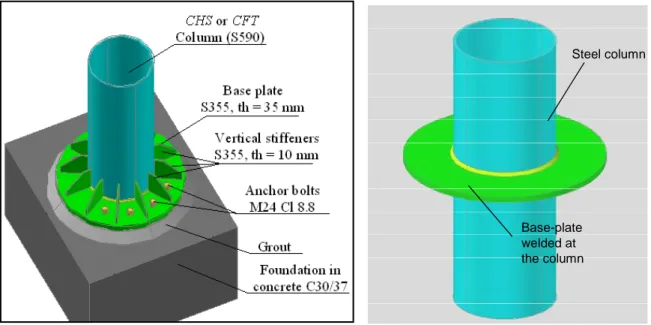
The idea is to satisfy the capacity design criteria by embedding the column inside the foundation. This solution is surely more performing for CFT columns. In other European projects (O. S. Bursi, S. Caramelli, G. Fabbrocino, J. Molina, W. Salvatore, F. Taucer and R. Zandonini “3D Full‐Scale Seismic Testing of a Steel‐ConcreteComposite Building at ELSA”, EUR 21299 EN, 2004), it was noted that the first joint can result semi‐rigid under cyclic loads. The reason of this behaviour is the elongation of the anchor bolts in tension when the grout will be damaged owing to the cyclic action of the earthquake. For this reason this second solution is proposed because it should perform better as rigid and full‐strength base‐joint.
Figure 12. Base joint: Solution 1 and Solution 2
The proposed innovative base‐joint with embedded column is designed according to the Strut&Tie mechanism for prefabricated concrete construction (pt. 10.9.6 EN 1992‐1‐1:2005) considering that the forces coming from the column in term of axial load, shear load and moment action are carried out by three forces forming in the foundation, according to the equilibrium system reported below. Steel column Base-plate welded at the column
According to this hypothesis, some formulas are then proposed for the characterisation of the resistance of the concrete strut and the design of the rebars that we need to add in the foundations.
Figure 14. Strut&Tie transfer mechanism in the foundation
For the fire situation, the over‐design criteria is to exploit the over‐resistance offered by the HSS to reach, under fire loads, better performance without protection or increased size, in other words without changing the sectional factor of the structural element.
The four types of columns previously designed under static loads are subjected to fire action with the help of the finite element program for non‐linear analysis, SAFIR, developed by University of Liège (J‐ M. Franssen, “SAFIR: A thermal/structural program for modelling structures under fire”, Engineering Journal 2005, 143‐158). According to the design procedure contained in EC1‐1‐2, 2D numerical model was performed considering different fire scenario (fire in the small compartment, fire in the open‐ space, fire in the full ground floor) and the implementing of the ISO curve (perspective approach) and natural fire curve (performance‐based approach) depending on: the design fire load; the presence of active prevention system; the dimension of the compartment; the dimension and location of the safety exit doors; the components of the partitions. Through the performed investigations, it was demonstrated that it is possible to reach the fire resistance requirements imposed by Eurocodes and National Standards (R60) by the use of HSS CHS columns without protection. Moreover, it is possible to reach exposure time greater than R60 with CFT columns and with or without HSS sections. The
4 Sdv barra b sd F n f φ π ⋅ = ⋅ ⋅ 4 Sdv barra b sd F n f φ π ⋅ = ⋅ ⋅ 4 Sdv barra b sd F n f φ π ⋅ = ⋅ ⋅ 4 Sdv barra b sd F n f φ π ⋅ = ⋅ ⋅
Table 2: Fire resistance for the different structural solutions
IV Design of Building Type 3
On the basis of the results obtained from the previous study case it evidenced that, for tall moment resisting frames (with four or five stories) under high seismic actions, the design is governed by the satisfaction of the damage limit states instead of the ultimate limit states. This means that for this type of structures, in very high seismic regions, the use of the HSS in not useful being important the dimension of the columns in order to satisfy the limitation of the interstorey drift for the DLS and the interstorey drift sensitivity coefficient in order to consider the second order effects. For this reason, in order to better identify a possible structural solution for the high seismic region, a five storey‐composite building with braced and moment resisting framing system was proposed to be designed with high‐strength steel CHS tubular columns and regular‐strength steel I‐beams with composite structural behaviour. This configuration corresponds to a typical office building, used in
(*) HSS with reduction factor proposed in the literature
59 53 59 63 53 Fire in lateral t t 65 55 65 65 55 Fire in Open Space
43 38
31 34
28 Fire in all ground floor
S 590 Q S 355 S 590 Q(*) S 590 Q S 355 Steel Grade Performance-based app R [min] Prescriptive Approach R [min]
Prototype structure with CHS columns 406 x 16 – 406 x 12
(*) HSS with reduction factor proposed in the literature
90 92 90 91 91 Fire in lateral t t 100 100 100 100 100 Fire in Open Space
91 91
80 79
79 Fire in all ground floor
S 590 Q S 355 S 590 Q(*) S 590 Q S 355 Steel Grade Performance-based app R [min] Prescriptive Approach R [min]
Prototype structure with CFT columns 355 x 12 – 355 x 10 - C30/37 - 8 φ 18
Following standard design practice in Greece, fire loading will be consider through appropriate paint or fiber‐coating protection of the steel elements.
A preliminary analysis and design has been already conducted, accounting for the EN 1993 and EN 1998 provisions for strength and serviceability. For this preliminary design, CHS columns were considered with HSS (590 MPa) and I‐beams from regular steel (355 MPa). The plan views and the description of the reference structure are illustrated in the following paragraphs.
Figure 15. Plan view of the office building considered for design and analysis.
IV.1.1.1 Moment resisting frame building
The selected steel moment resisting frame (Figure 16) is a structural system in which beam‐column connections are realized as full strength rigid joints. As a result, the frame members resist lateral loads through their flexural stiffness and strength. This structural system provides ductility to the structure and high energy absorption, making it ideal for seismic prone areas where the design is oriented towards this target. The drawback of this approach is the increased lateral deformation of the structure which has to be within the serviceability limits imposed by the Eurocode. Moment resisting frames are able to provide an advanced energy dissipation mechanism, thanks to their large number of dissipative zones. Through this mechanism, the structure is expected to satisfy all the code imposed requirements. On the other hand, fulfilment of the requirements necessary to guarantee the serviceability limit state check becomes more and more difficult as the height of the building increases. This is due to the decreased lateral stiffness the framed structures posses, which
Figure 16. 3D elevation view of the moment resisting building.
IV.1.1.2 Braced frame building “Type 1”
Steel moment‐resisting frames are susceptible to large lateral displacements during severe earthquake ground motions. Therefore, special attention is required in order to limit the damage to non‐structural elements as well as to avoid problems associated with P‐Δ effects and brittle or ductile fracture of beam to column connections [FEMA, 2000]. As a consequence, engineers in the US have increasingly turned to concentrically braced steel frames as an economical way to resist earthquake loads.
Concentrically braced frames can be designed to carry the total value of the seismic horizontal forces. According to Eurocode 8 and ECCS recommendations, the design value of the q‐factor of X‐ braced frames is assumed equal to 4au/ay.
The X‐bracing system consists of two diagonal braces pin‐connected to a surrounding frame. The diagonal elements are subjected to compression and tension forces respectively, which cause increased axial load to the supporting columns. This has to be taken in to account for the column design.
The “Type 1” office building with concentric braces selected for design by UNITH is shown in the next figures.
Figure 17. 3D view of the “Type 1” braced frame building Figure 18. View of the “Type 1” typical braced frame, y‐direction Figure 19. View of the “Type 1” typical braced frame, x‐direction
IV.1.1.3 Braced frame building “Type 2”
Figure 20. 3D view of the “Type 2” braced frame building Figure 21. View of the “Type 2” typical braced frame, y‐direction Figure 22. View of the “Type 2” typical braced frame, x‐direction Preliminary 3‐dimensional drawings for the moment resisting frame and braced frame connections are proposed as illustrated bellow. Moment resisting type of joint is decided to be rigid full strength connections in order to activate the formation of plastic hinges at the beams’ ends as the beam‐to‐ column joint should possess enough overstrength with respect to adjacent beams. The type of joint referring to the braced system is considered to be a simple transverse loading transfer connection.
V Fa
From th extracte • T • T Figure 2abricatio
he previousl d: Two differen Two differen 23. View of th Figure 24on of th
y designed nt tubular HS nt types of be he beam‐to‐co . View of thehe spec
structures, SS columns (S eam‐to‐colu olumn momen beam‐to‐coluimens
the followi S590 CHS 35 mn joints (se nt resisting, rig umn braced‐fr ng structura 55x12 and S5 ee Figure 5 a gid full‐streng rame joint. al elements 590 CHS 324x and Figure 11 gth joint.to be test
x10); 1);
For each specimen, all the pieces for the fabrication are reproduced in singular drawings and then checked by each partner according to the requirements of the test set‐up. Some examples of these drawings are reported here below; all the drawings are reported in Appendix 4. All the specimens are produced with S275 and S355 steel grades for the beams and the plates and HSS 590 steel grade for the circular columns. For all the specimens, weld material undermatching the mechanical properties of HSS (S590) and overmatching the mechanical characteristic of the mild steel (S275 or S355) was selected. In detail a weld metal G 46 4 M G4Si1 is used. Here below, some photos of the already produced specimens are reported. All the specimens should be delivered before the end of April.
Appendix 1: Economical study
UNIVERSITY OF LIEGE
Department ArGEnCO
MS
2F Division
Field of application of high strength steel circular tubes for
steel and composite columns from an economic point of
view
ATTEL Project, Internal report
Hoang Van Long Ly Dong Phuong Lam Jean‐François Demonceau Barbara Rossi Jean‐Pierre Jaspart
1. Introduction
High strength steel is the term generally employed for steel presenting a proof strength higher than 450MPa. The use of high strength steel (HSS) in load‐bearing structures has fairly during the last decades thanks to its advantages as underlined by authors in [1, 6, 7, 9]. The reason lays not only but mainly in its economic interest compared to steel, whose cost increases slower than its strength. However, as the stiffness of HSS structures is smaller than the one of normal steel (NS) structures, the second‐order effects and the serviceability requirements considerably limit the use of HSS in load‐bearing structures.
But this question has been sporadically considered in the researches concerning the behaviour of structures made of HSS. Therefore, the economic profit of using HSS in constructions needs to be more adequately studied in order to highlight the advantages of HSS in each type of structures. The present work aims at investigating steel and composite construction using circular steel tubes for the columns. The objective is to define the two respective domains where HSS and NS respectively are of economic interest. Two points will be simultaneously reported: (1) provide a general view of the economic benefit of the use of HSS; (2) establish the basis for choosing the material (HSS or NS) for framed structures before designing it.
The present research compares the costs of two columns made of HSS and NS. Steel with yield strengths varying from 500 N/mm2 to 700 N/mm2 will be considered as HSS [4] while S355 steel is considered as NS. The strength, stability and stiffness conditions according to Part 1‐1 of Eurocode 3 [3] and Part 1‐1 of Eurocode 4 [5] will be taken into account in the optimum cost design for steel and composite columns. Concerning the analysis of structures made of HSS, the rules of Part 1‐12 of Eurocode 3 will be used [4]. Simple columns, columns in braced/un‐braced frames and general frames will be investigated. In each case, the algorithms are implemented and the resulting automatic calculation allows examining almost practical possibilities.
2. Investigation for simple columns
Let us consider a simple column as the one depicted in Fig.1. The cost of two solutions with the same length and under the same loading but using two different steel grades, NS and HSS, is evaluated. In order to be comparable, the optimum cost design for each column is needed (Section 2.1). Afterwards, a global comparison is made in order to evaluate which grade is of economic interest (Section 2.2). An adequate number of case studies to be carried out is then chosen in order that the global study provides general results (Section 2.3). The conclusions for simple columns are provided in Section 2.4.
Fig.1. Single column 2.1. Optimum cost design for single columns
The optimum cost design provides the cheapest structure among the admissible solutions respecting the necessary safety conditions. Generally, an optimum cost design consists of three main steps: (1) the application of the rules controlling the safety of the structure that will be the constraints of the optimal problem (Sections 2.1.1 and 2.1.2); (2) the establishment of the cost function representing the objective to be minimized (Section 2.1.3); (3) the arrangement of the problem under mathematical optimal procedure, and the choice of a suitable algorithm to solve the problem (Section 2.1.3). 2.1.1. Safety condition for steel columns The very widespread safety rules of Eurocode‐3 [3] are used in the present work. Only a few recalls necessary for the good comprehension of the reader are provided below. ‐ The input quantities are: ‐ fy is the characteristic (k)/design (d) value of the yield strength;
‐ E is the modulus of elasticity of the steel; kN/m2 is taken in the present work; ‐ D is the outside diameter of the tube; ‐ t is the tube thickness;
‐
is
the length of the column, it is also the buckling length in this case.
‐
,
are the respective design values of the compression and the bending moment. If the bending moment is not uniform, the equivalent moment is used. 9 2,1 10 E= x
l
Ed N MEd‐The intermediate quantities: ‐ is the cross‐section area; ‐ is the elastic section modulus; ‐ is the plastic section modulus; ‐ is the second moment of inertia of the cross‐section; ‐ is the design plastic compression resistance; ‐ is the design elastic bending resistance; ‐ is the design plastic bending resistance; ‐ is the radius of gyration of the cross‐section; ‐ is the non‐dimensional slenderness of the column where the elastic buckling force is provided in Eq. (2); (2)
‐ is used to determine the reduction factor , with:
for S355 and for HSS, the tubes are supposed to be hot finished. The reduction factor is calculated using Eq. (3);
(3)
‐ is the factor taking into account the reduction of the design plastic resistance due to axial force: for section of Class 3; 2 ( ) A=
π
t +dt 4 4[
(
2 ) ]
32
elW
d
d
t
d
π
=
−
−
3 31
[
(
2 ) ]
6
plW
=
d
−
d
−
t
4 4[
(
2 ) ]
64
I
=
π
d
−
d
−
t
p yN
=
f A
el y elM
=
f W
pl y plM
=
f W
I
i
A
=
pl y crN
l
f
N
i
E
λ
π
=
=
2 2 crEI
N
l
π
=
2 0, 5[1α λ
( 0, 2)λ
] Φ = + − +χ
0, 21
α
=
α
=
0,13
2 2 1χ
λ
= Φ + Φ − yyC
1
yyC
=
‐ Member verification: (4) 2.1.2. Safety condition for composite columns The rules of Eurocode‐4 [5] for composite columns are summarized in this Section. ‐The input quantities: ‐ is the characteristic (k)/design (d) value of the yield strength of the steel tube; ‐ , are the characteristic value and the design value of the strength of the concrete; ‐ , are the characteristic value and the design value of the strength of the rebar;
‐ , , are the modulus of elasticity of the steel, the concrete and the rebar. The values of kN/m2 and kN/m2 are used in the present work. ‐ D is the outside diameter of steel tube; ‐ t is the tube thickness ; ‐ b is the distance from the centre of the rebar to the inside face of the tube (Fig.1);
‐
is
the length of the column, it is also the effective length in this case.
‐
,
are the design values of the axial load and of the bending moment. ‐ Strength of the cross‐section (Interaction curve)Due to the non‐symmetry of the stress‐strain response of concrete under tension and compression, the shape of the interaction curve for composite sections is similar to the curve shown in Fig.2, with the particular points: A, B, C and D. With circular sections, the volume of computation to determine this curve by hand is quite large. Thus, in order to be able to implement the equations for automatic calculations, the following assumption is made (Figs. 3a and 3b): the area of reinforcements is supposed to be a continuous ring instead of distinct rebars. The ensuing error decreases when the number of rebars increases.
1
1
1
Ed Ed Ed p yy Rk crN
M
N
N
C M
N
χ
χ
+
−
≤
yf
ck f fcd sk f fsd a E Ec Es 83, 2 10
cE
=
x
E
s=
2,1 10
x
9l
Ed N MEdUsing the symbols reported in Fig.3, all the following quantities can be expressed using the location of the neutral axis that only depends on the angle (Figs.3c and 3d): 3 2 2 ( ) 4 ( ) s A r r b r b
π
= − + − ; 4 2 2(
)
4 (
)
sA
r
r
b
r
b
π
=
− −
−
; 2 2 1 1 1 1 2 2 1 1 2 2 1 1 sin arctan if ( sin ) 0 ( sin ) / 2 if ( sin ) 0 i i i i r r r r r r rθ
θ
θ
θ
π
θ
− > = − − ≤ ; 2( / 2
sin
cos )
i i i i iA
=
r
π
− −
θ
θ
θ
; 3 32
cos
3
i i iW
=
r
θ
; 1(
a2
22
1)
yd(
c 3 2 4)
cd(
s2
42
3)
sdN
θ=
A
+
A
−
A f
+
A
+
A
−
A
−
A f
+
A
+
A
−
A f
; (5) 1(
1 2)
yd(
2 3 4)
cd(
3 4)
sdM
θ=
S
−
S
f
+
S
−
S
+
S
f
+
S
−
S
f
. (6) 1θ
Let vary from to , using Eqs. (5) and (6), it is possible to depict the interaction curve (from A’ to A of Fig.3.f) containing the particular points A, B, C, D (Figs. 3e and 3f): ‐ Point A corresponds to ; ‐ Point B corresponds to ; is determined by Eq.(5), but ; ‐ Point D corresponds to ; ‐ Point C is deduced by points B and D. In the case of no reinforcements, leading to . ‐ Member verification: The simplified method allowed by Eurocode‐4 is summarized as follows: Two values for the effective flexural stiffness are distinguished: ; ;
where is the concrete modulus of elasticity taking into account the influence of long‐term effects, it depends on the values of long and short term loading and the creep coefficient (for reason of simplification, in the present work); are the respective second moment of inertia of the steel, the rebar and the concrete. is used to calculate the elastic critical axial compression force and, subsequently, the relative slenderness whereas is used to determine the second‐order effect of the member. (1) The resistance of the member under axial compression is verified using: ,
1
Ed pl RdN
N
χ
≤
, (7) where is the plastic compression resistance, calculated with Eq.(5) in which ; is the characteristic value of ; is calculated with Eq.(2) using ; is calculated1
θ
−
π
/ 2
π
/ 2
1 / 2θ
=π
* 1θ θ
=
θ
* *0
N
θ=
1 0θ
= 0 s A = r3 =r4(
EI
)
eff=
E I
a a+
E I
s s+
0, 6
E I
cm c ,(
EI
)
eff II=
0,9(
E I
a a+
E I
s s+
0,5
E I
cm c)
cm E /1, 6 cm c E =E I I Ia, s, c(
EI
)
eff ,(
EI
)
eff II , pl RdN
θ
1=π
/ 2N
pl Rk, , pl RdN
Ncr(
EI
)
effλ
, ,
1
300 1
/
Ed II Ed Ed Ed cr IIL
M
M
N
N
N
⎛
⎞
=
⎜
+
⎟ −
⎝
⎠
, where is calculated using Eq.(2) together with . Fig.4: Member verification for composite columns ‐ Conditions of use of the simplified method: To apply the simplified method for circular hollow sections, the following conditions should be satisfied: ‐ The member is not too slender:λ
≤
2, 0
; ‐ The area of rebar shouldn’t exceed 6% of the one of concrete core. ‐ The section belongs to Class 3 at the minimum, in order to avoid the local buckling of the steel tube. 2.1.3. Establishment of optimum problem After having the safety condition of columns, we can build up the optimal problem that may be described as the following. ‐ Cost function and unknowns: The following parameters may be considered as the variables of the optimal problem: ‐ The diameter D and thickness t for steel columns; ‐ The diameter D, thickness t, distance b (Fig.1), area of rebar, class of concrete and grade of rebar for composite columns. However, the class of concrete and the grade of rebar are discontinuous quantities with very few practicable values. And thus they are not considered as regular variables of the problem. , cr IIN
(
EI
)
eff II,conclusions useful for any time and place, a large field of the mentioned costs should be investigated, obviously leading to the complexity of the problem. To avoid this, the following problem for composite columns is considered: two solutions of columns are compared with the same length, the same class of concrete, the same density (%) of rebar, under the same load, but using two different values of strengths of steel tubes. The variations of length, loads, concrete class, and rebar density will be considered as the parameters (input variable) of the optimum research problem. Therefore, the following cost function is adopted: , (9)
where Acs is the area of concrete and rebar; , are, respectively, the cost per volume of steel
and of reinforcement concrete (euros/m3).
Meaning that, when calculating the cost, the concrete and rebars are considered as one single material (reinforced concrete). The parameter ccs obviously depends on the class of concrete
and the density of rebar.
Finally, two variables have to be examined: the diameter D and the thickness t. In reality, market catalogues for steel tubes provide discontinuous quantities for the couple D and t. But, in the present research, in order to generalize the results and simplify the mathematical problem, the diameter D and the thickness t are considered as continuous quantities.
‐ Constraints:
Using the safety analyses of columns presented in Sections 1 and 2, the constraints for the optimum research problem are summarized as follows:
‐ Requirement of section classification: Eq.(1);
‐ Requirement for member buckling resistance: Eq.(4) for steel columns, Eqs.(7) or (8) for composite columns; ‐ Constitutive condition: . ‐ Geometric interpretation of the optimum research problem: The optimum research problem can be qualitatively interpreted as it is depicted in Fig.5. ( a a cs cs) C=l A c +A c a c ccs
/ 2
t
≤
D
, (10)
where C(x) is the cost function (Eq.(9)); are the constraints.
The method of feasible direction is chosen to solve the problem. The explanation of this method is abundantly reviewed in the literature (e.g. [7]). Herein, the main ideas are briefly recalled: (1) an initial point SP is found inside the feasible zoon (Fig.6); (2) a feasible direction S is established, with which a new point considered as better than the last point (the cost function decreases with the constraints still respected) is found; (3) the allowed distance in the direction S is limited by a scalar . The procedure is repeated until an acceptable convergence (optimum) is reached, it is the case when no feasible direction is found. The qth iteration of the process can be written as: Fig.6: Illustration of the optimum research problem procedure In the procedure, it is necessary to calculate the gradient of C and g although it is sometimes difficult to compute the derivative of these functions such that the gradient is often replaced by the sensitivity: 2.2. Definition of the index of interest At the present time, it seems that the grade of steel S355 is the most popular in construction, it is thus chosen as the reference material. Eq.(9) (with the sub‐scripts “355” and “HSS” to distinguish
Find
x
=
[ , ] such that
D t
C
( )
x
→
min
but
g
j( )
x
≤
0,
j
= ÷
1
n
( )
jg x
*α
1 * q=
q−+
α
qX
X
S
( )i ( i i) ( )i i i x x x g x x x ∂ ≈ + Δ − ∂ Δ g g, , 355 , 355 355 ,355 ,355 355
(
/
/
)
/
(
/
)
a HSS a HSS cs HSS cs HSS a cs csA
c
c
A
c
c
C
C
A
A
c
c
+
=
+
. (11)It is clear that if , then HSS is of interest; on the contrary, if then NS is of interest; the neutral case occurs if .
2.3. Field of investigation for simple columns
In order to draw conclusions that might be true for a lot of practical cases, the following fields are investigated.
‐ the columns length l varies from 3 to 8 m;
‐ the compression force varies from 500 to 6000 kN;
‐ the maximum bending moment to compression force ratio varies from 0 to 0.75 m;
‐ according to [4], S500, S550, S620 and S690 steels have be considered as HSS (with fy = 500,
550, 620 and 690 (N/mm2) respectively). In the present work, various steel grades within 500 and 700 are considered. However, in Appendix, in order to limit the number of charts, three supposed HSS steels are examined: S500, S600 and S700; the results concerning an intermediate steel grade could be interpolated using the results of the other steel grades.
‐ the characteristic value of the compressive concrete cylinder strength varies between
(N/mm2); the density of rebar varies from 0% to 6%;
‐ the cost of HSS to cost of S355 ratio . According to [1], these values
(interpolated using Fig.1 in [1]) are: ; ; ;
.
‐the cost of reinforced concrete to the cost of S355 ratio . At the moment, this value in Belgium is around 0,03. 2.4. Numerical results and comments for simple columns In order to illustrate the procedure presented in the above sections, an example is provided here below for a 5m length column, submitted to a compression load of 5000 kN and a uniform bending moment of 100 kNm. The costs of two columns are compared: / 1 HSS NS C C < CHSS/CNS >1 / 1 HSS NS C C = Ed N ,max Ed
M
NEd 25 40 ck f = ÷ 355 / 1,1 1, 6 HSS c c = ÷ 500/ 355 1,138 c c = c550/c355=1, 260 c620/c355 =1, 340 690/ 355 1, 382 c c = 355 / 0, 02 0, 05 cs c c = ÷‐ Optimal solution for column using S690: D=33,73 cm; t=1,10 cm. ‐ Comparison of costs:
The ratio
=1,46 , meaning that the use of HSS can provide an economic interest. Let’s consider [7], in this case, the economic interest of using S690 compared to S355 would be 5,6%. (2) For the composite column: ‐ Optimal solution for column using S355: steel tube D=40,02 cm, t = 0,67 cm; = 45,17cm2 (= 4% of the concrete area). ‐ Optimal solution for column using S690: steel tube D=31,61 cm, t = 1,03 cm; = 26,38cm2 (= 4% of the concrete area). ‐ Comparison of costs: Using Eq.(11), one has:
If is adopted again, the use of S690 is of interest if the unrealistic condition is respected. In this case, HSS does not provide any economic interest.
After all calculations achieved in the chosen filed of applications, it is possible to draw several conclusions:
‐ In many case, for steel columns, the use of HSS leads to considerable economic profit in comparison with S355 steel. In fact, the use of HSS in case of stocky columns provides the greatest advantage while NS is more economic in case of slender columns. Moreover, the interest of using HSS decreases when the eccentricity increases.
‐ Depending on the column length and the loading condition (M/N), the charts A1 to A12 in the Appendix show the ratio between the area of HSS columns and the area of NS columns (for simple columns). With these charts, the user can obtain the economic benefit of the use of HSS if the material costs are known. For reason of simplification, only a few charts are presented. ‐ Even if the relative cost is varying a lot, very few of cases where the use of HSS in composite columns gives economic profit. By way of conclusion, it is not economic to use HSS tubes for composite columns under static loading.
3. Investigation for columns in frames
355 355/ 690 690 c A c A c355/c690 690/ 355 1, 382 c c = s A s A 690 355 355 355 98, 95 / 685,8 /cost of column using 690
cost of column using 355 81, 42 1175,1 /
cs cs c c c c S S c c + = + 690/ 355 1, 382 c c = 355 / 1/ 8,8 cs c c ≥ 355 / cs c c
Similarly to simple columns, the above described procedure is carried out to compare two solutions of column using NS and HSS. a) column in braced frames b) column in un‐braced frames Fig.7. Column in frames 3.1. Analysis of columns in frames 3.1.1. Effective length
Traditionally, the concept of effective length has been used to evaluate the stability of columns in frames, using the analogy of the simple column of same length. Wood’s research [11] on the effective length is adopted in the present work. According to this, the effective length depends on the stiffness coefficients at column crossings: c s s c s bs R R k R R R + = + + ; (12) c i i c i bi R R k R R R + = + + ; (13)
where is the stiffness of the considered column;
and are the stiffness of the upper and lower columns respectively; and are respectively the sum of the stiffness of all beams connected at the superior node S and the inferior node I of the considered column (Fig.7).
With
k
sand , we can obtain the effective length of the column using the charts that were developed by Wood [11]. However, applying the charts is not very suitable to the automaticc R Rs Ri bs R Rbi i k
As soon as the effective length is known, the stability analysis of columns in frames is similar to the one of single columns. 3.1.2. Horizontal displacement of column in un‐braced frames The stiffness of columns made of HSS is smaller than the one of columns made of NS, such that the horizontal displacement might become important. Taking into account the displacement in the optimal problem for columns in un‐braced frames is necessary in order to have realistic results. The horizontal displacement of the column in un‐braced frames due to the horizontal load (Fig.7) is calculated using the following formula [8] 3
3(
)
1
12
4 3
3
2
k i s i s c i s i sP l
k
k
k k
EI
k
k
k k
⎛
+ −
⎞
Δ =
⎜
+
⎟
−
−
+
⎝
⎠
, where E is the modulus of plasticity for steel/composite column;P
k is the characteristic value of the horizontal load (Fig.8). If the second‐order effects are taken into account, the displacement becomes 33(
)
1
1
12
4 3
3
2
1
/
k i s i s c i s i s Ek crP l
k
k
k k
EI
k
k
k k
N
N
⎛
+ −
⎞⎛
⎞
Δ =
⎜
+
⎟⎜
⎟
−
−
+
−
⎝
⎠⎝
⎠
, with is the characteristic value of the vertical load (Fig.8). 3.2. Optimum problem for columns in frames If columns in braced frames, the optimum problem is similar to the one if simple columns. A procedure for calculating the effective length using Eqs.(14) and (15) is simply added. The load combination shown on Fig.8a is used for the stability study, achieved using Eqs.(4), (7) and (8).If columns in un‐braced frames, besides this new procedure, another limitation has to be taken into account: the horizontal displacement of the columns must remain under l/250, where l is the column length. For that case, the load combination reported on Fig.8b is adopted and must respect the displacement condition written as 3
3(
)
1
1
/ 250
12
4 3
3
2
1
/
k i s i s c i s i s Ek crP l
k
k
k k
l
EI
k
k
k k
N
N
⎛
+ −
⎞⎛
⎞
Δ =
⎜
+
⎟⎜
⎟
≤
−
−
+
−
⎝
⎠⎝
⎠
. k Na) Ultimate state b) Serviceability limit state
Fig.8. Two states to be verified for column in un‐braced frames
For the columns in un‐braced frames, the equivalent uniform moment factor =1 should be adopted since the extremities of the column are the critical parts to be considered in the stability problem (Fig.9). In this case, it is not necessary to verify the cross‐sections strength condition.
Moreover, it is worth noting that, if the effective length is calculated using the mentioned equations (14) and (15), the P‐ effect is taken into account. And therefore, the bending moment (Fig.8a) should be calculated using the first order theory. Fig.9. Critical sections for columns in un‐braced frames 3.3. Field of investigation for columns in frames For the two types of column shown in Fig.7, the field of investigation of the simple column (Section 2.3) is reused. Additionally, the variation of the coefficients and and of the horizontal load have to be taken into account. Besides, the characteristic value of the axial load has to be considered (Fig.8b). In order to be able to compare two solutions of columns (using HSS and NS) and decrease the complexity of the problem, the following assumptions are made: ‐ The stiffness at the bottom and top ends of the column are the same
R
s=
R
i=
R
c; ‐ The same configuration of beams is used in every case: . m CΔ
,max EdM
i k ks bs bi b R =R =R‐ The ratio varies from 1/250 to 1/2. This can be explained by the fact that if one considers a frame of stories and bays as the one shown in Fig.10. Prior to any calculation, the approximately estimations of the vertical load and the horizontal load acting on the considered column are: Fig.10. Evaluation of the loads acting on columns 1 1 2 2
2
2
A B A B sB
B
B
B
N
=
n p
+
+
; . Consequently, one has: 2 2 / 2 A B b w h P N B B p n = + ⎛ ⎞ ⎜ ⎟ ⎝ ⎠ . (17) In traditional buildings, the following limitations are used (units are kN and m): ;50
≤ ≤
p
120
; ; ; . These limitations introduced in Eq.(17) provide us with the suggested upper and lower bounds. 3.4. Comparison procedure for columns in frames The same system of beams is supposed to be used for the two cases of column, meaning that we consider a given set of beams and want to compare the optimal NS and HSS columns in this building. / k Ek P N s n nb 1 1 1 2 A B s b B B P w n h n + =10
≤ ≤
w
20
2≤nb ≤83
≤ ≤
h
5
6≤B2A+B2B ≤16Step 2: Achieve the optimum research problem (Section 3.2) for the column made of steel
S355.
Step 3: Calculate for this optimal column section.
Step 4: Determine the value of using Eq.(16) and the previously calculated k and .
Step 5: This value of is considered as an input of the optimum research problem for HSS column. It is worth pointing that and k are, of course, updated during the procedure such that Eq.(16) is satisfied.
Step 6: The comparison of the two types of column can be made (Section 2.2).
3.5. Numerical results and comments for columns in frames
In order to clarify the comparison procedure, an example is presented in details: Let’s consider a column in an un‐braced frame with a length of l = 4m, submitted to = 2000 kN and
= 33 kN (see Fig.8). One compares the price of two columns made of S355 and S690 grades.
Step 1: Let consider k=0.2 for instance, the effective length is calculated using Eq.(15):
cm.
Step 2: The optimum research problem is solved for a column made of S355:
cm; cm; cm2; the elastic buckling load kN; the stiffness kNm; (sway column) and the relative horizontal displacement .
Step 3: With the optimal section: kNm.
Step 4: The stiffness of the contiguous beams is calculated using Eq.(16): kNm.
Step 5: Then, the optimum research problem is solved for a column made of S690 and
characterized by the same configuration of beams ( kNm): cm; cm; cm2; the elastic buckling load KN; the stiffness
kNm; the coefficient ; the effective length cm;
(sway column) and the relative displacement . c R b R Rc b R c R Ed N k P
450,5
fl
=
,35536,14
opD
=
,3550, 78
opt
=
A355 =86, 65N
cr,355=
13480
,3558108
cR
=
N
Ed/
N
cr,355=
6,92
/
l
1/ 418
Δ =
7113,15 c R = 56918 b R = 64862 b R =D
op,690=
28, 60
,6900,93
opt
=
A690 =81,10N
cr,690=
8725
,6904077
cR
=
k690 =0,125l
f,690=
430
,690/
4,36
Ed crN
N
=
Δ =
/
l
1/ 250
=‐ If braced frames and steel columns, the domain of interest of HSS (positive economic profit) is greater than the one for simple columns. This can be explained by the fact that the simple column effective lengths (being the column length) are the same for NS and HSS columns. On the contrary, the effective length of the column in braced frames (with the same beam system) is smaller if HSS is used instead of NS. Even if the bending moments in braced frame are not significant in practice but different values of the eccentricity are considered in the present work. ‐ The economic benefit of the use of HSS in un‐braced frames is smaller than the one in the case of braced frames. The displacement condition is responsible of this, emphasizing the disadvantage of the use of HSS. The volume reductions are also shown in the Appendix.
‐ Generally, the terms sway (if the vertical to elastic critical load ratio ) and
non‐sway frames are used for frames.
It is not convenient to use this kind of classification for a comparison of the economic interest, but because these terms are widely used, the following comment has been drawn looking at the numerical results: there is no benefit in using HSS in sway frames with for a comparison made on the basis of frames using S355 steel.
‐ As it is the case for single columns, there are very few possibilities of composite columns for which the use HSS tubes provide an economic profit.
4. Investigation for frames
To design a frame, the following quantities are necessary: vertical loads, horizontal loads, frame configuration (number of stories, number of span, height of stories…) and technology conditions, etc. It seems unfeasible to consider a certain amount of frames by varying the mentioned quantities and cover almost all practical possibilities. Therefore, even if the optimum design problem could be defined (taking into account the strength, stability and stiffness conditions) and solved using appropriate computational software, the resulting charts wouldn’t be similar to the ones obtained in the case of isolated columns. Nonetheless, the comments of Section 3.4 are also useful for frames. It is the reason why two simplified procedures are proposed here below to help decision‐making regarding the steel grade, before any detailed design of the frame be carried out.
The first one: This method consists of the following steps: Firstly, prior to any computation,
the engineer’s expertise leads him to first choose the member sizes of the frame. Afterwards, a global analysis of the frame is introduced in two cases: (1) the first case aim to find the critical internal forces in the columns (design values); (2) in second case we apply only horizontal load with characteristic value to obtain this kind of load distributing in each column. Finally, with the mentioned internal forces and horizontal loads, using the charts provided in the Appendix we could assess the economic interest of the use of HSS. / <10 Ed cr N N / <10 Ed cr N N