ScienceDirect
Available online at www.sciencedirect.com
Procedia Manufacturing 47 (2020) 686–692
2351-9789 © 2020 The Authors. Published by Elsevier Ltd.
This is an open access article under the CC BY-NC-ND license (https://creativecommons.org/licenses/by-nc-nd/4.0/) Peer-review under responsibility of the scientific committee of the 23rd International Conference on Material Forming. 10.1016/j.promfg.2020.04.210
10.1016/j.promfg.2020.04.210 2351-9789
© 2020 The Authors. Published by Elsevier Ltd.
This is an open access article under the CC BY-NC-ND license (https://creativecommons.org/licenses/by-nc-nd/4.0/) Peer-review under responsibility of the scientific committee of the 23rd International Conference on Material Forming.
ScienceDirect
Procedia Manufacturing 00 (2019) 000–000
www.elsevier.com/locate/procedia
2351-9789 © 2020 The Authors. Published by Elsevier Ltd.
This is an open access article under the CC BY-NC-ND license https://creativecommons.org/licenses/by-nc-nd/4.0/) Peer-review under responsibility of the scientific committee of the 23rd International Conference on Material Forming.
23rd International Conference on Material Forming (ESAFORM 2020)
Thermal Analysis of Solidifying Steel Shell in Continuous Casting Process
Hoang Son Tran
a, Etienne Castiaux
b, Anne-Marie Habraken
a,c,*
aUniversity of Liege (ULiege), ArGEnCo Dpt, Materials and Solid Mechanics Unit, Allée de la Découverte, 9 B52/3, B 4000 Liège, Belgium bEBDS Engineering S.p.r.l. 39 Avenue du Progrès,B-4100 Seraing
cF.R.S.-FNRS, Fonds de la Recherche Scientifique, Rue d'Egmont 5, B 1000 Bruxelles, Belgium
* Corresponding author. Tel.: +32 4 3669430. E-mail address: [email protected]
Abstract
A finite element simulation of the steel shell formation in continuous casting has been developed. The current research is focused on the solidification of molten steel during the initial stages of the mould cooling. The model allows predicting the temperature field throughout the process: temperature gradient, solidification front, cooling rates. In stationary state, the prediction of shell thickness reasonably agrees with analytical models and experimental observations. The simulation tool is used to study the alteration of the mould thermal field in case of sticking defects encountered in industrial practice. A numerical analysis increases the understanding of the phenomena.
© 2020 The Authors. Published by Elsevier Ltd.
This is an open access article under the CC BY-NC-ND license https://creativecommons.org/licenses/by-nc-nd/4.0/) Peer-review under responsibility of the scientific committee of the 23rd International Conference on Material Forming.
Keywords: Continuous casting; Sticking breakout; Thermal analysis; Lagamine; Finite element
1. Introduction
In recent years, the production of steel by the continuous casting process keeps increasing, the reasons for this growth are the product quality and the cost-effectiveness. This process is described as follows: liquid steel is poured into a copper mould which is kept at a medium temperature thanks to a cooling system. The molten steel in contact with the mould quickly starts to solidify (primary cooling). Extracting rolls under the mould pull the strand and keep it moving forward in the caster while water continues cooling it (secondary cooling). The strand can be cut when all of the section is solidified. Many process parameters influent the quality of the product such as: casting speed, mould level, mould oscillation, composition of the steel, superheat temperature, secondary cooling conditions... A large number of mathematical models of the whole process are reported in the literature. Some analytical solutions for the development of the stress field in the strand in the course of solidification were developed by Weiner and Boley [1], as well as by Tien and Kaump [2]. Although these analytical solutions provide global reference results for
industrials and for the verification of other numerical models, they are often unable to provide accurate local information in real applications presenting defects. Their assumptions are too simple for the numerous complex physical phenomena associated with the solidification. Therefore, the requirement to provide more flexible, accurate and refined descriptions makes others types of numerical analyses crucial tools.
Various numerical methods have been used to solve the equations governing the thermo-mechanical behaviour in the continuous casting process. Hattel et al. [3] used the finite volume difference methods to simulate three-dimensional thermo-elastic stresses. Jung-Eui Lee and his collaborators [4] proposed a finite volume method for the coupled fluids flow problem. Heinlen and Mukherjee [5] used the boundary element method analysis to predict the mechanical behaviour in one-dimensional solidification of an aluminum bar.
The finite element method (FE) is an approach specially adapted to the management of a wide variety of non-linearities and geometric shapes. For that reason, many of the numerical researches on continuous casting process use this method. In 2D cases, it has been applied to simulate shell thinning
breakouts [6], ideal taper optimization [7], stresses during solidification process [8-12]. A 3D thermo mechanical model has been developed by Koric and Thomas [13]. Recently, Zhang et al. developed an algorithm of concurrent simulation of fluid flow and stress-strain analysis for continuous casting [14]. However to the authors’ knowledge, no FE simulation specifically simulates the sticking breakout problem.
This paper presents an application of a 2D thermal finite element model to predict temperature field throughout the process as well as the shell thickness. The first results of a sticker breakout model are presented hereafter. This study is based on the Lagamine code which has been previously applied on the modelling of the continuous casting process [15-16]. This code is developed by MSM group of the University of Liege.
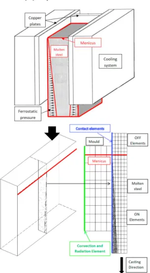
2. Model Description 2.1. Geometry of the problem
Fig. 1. Illustration of the 2D plan studied by finite element strategy of continuous casting.
To simulate the crack propagation due to the sticking phenomenon, a 2D vertical model is a first approach. The finite element model is developed in two stages: a first thermal model
to reach the stationary state and then a second model to take into account the sticking allowing the analysis of the crack propagation. The vertical section studied corresponds to a middle section of the ingot mould. By symmetry, the mesh of the slab concerns its half thickness, the mesh height is the height of the mould (see Fig. 1). The application case is recovered from [15]. The meshed mould consists of a 40mm thick copper bloc cooled by its outer face. In reality, the mould is cooled by a circulation of water, here the radiation convection exchanges are adjusted to reproduce a realistic thermal field in the mould.
2.2. Heat transfer finite element analysis
Two types of laws are required in the thermal modeling approach:(i) bulk heat transfer by conduction, including the heat accumulation in the solid and (ii) surface heat transfer by convection and radiation. The classical non-linear equation of conduction is: int p
T
T
T
k
k
Q
c
x
x
y
y
t
(1) with the temperatureT x y t K
( , , ) [ ]
, the thermal conductivity,
( ) [ .
1.
1]
p
c T J Kg K
the apparent heatcapacity, the density, the power
generated per volume in the work-piece, and t the time. Heat exchange by convection and radiation is defined by:
4 4
0 0
( . )
(
)
(
)
k T n
h T T
T
T
(2)where h is the convection coefficient [W.m-2.K-1], σ is the
Stefan-Boltzman constant (5.67×10⁻⁸W.m-2.K-4), ε is the
emissivity coefficient, T0 is the initial temperature
The latent heat of solidification is integrated in the definition of cp. All the data related to the thermo-physical properties of
the slab are recovered from [15] however due to confidentiality reasons steel composition is not provided.
2.3. Finite element model
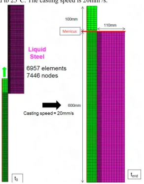
Fig. 2 shows the mesh of the finite element model used with its dimensions. The copper mould and the steel are modelled using quadrilateral elements with 4 nodes and 1 integration point. The element size is refined in the area near the contact between the mould and the steel. This mesh contains 6957 solid elements and 7446 nodes, the size of the slab refined elements is 2mmx2mm and that of the mould is 3mmx3mm. The contact between the mould and the slab is simulated by an interface element [17]. The thermal parameters of the slab are presented in Fig. 3. The conductivity and thermal capacity of the copper are 401 mW/ mm and 2776 mJ / mm³ respectively. They are assumed to be constant with temperature. The convection coefficient h is 4 W.m-2.K-1, the radiation coefficient is 10-8
W.m-2.K-4 on the external face of the mould. They are adjusted
to recover the temperature measured in [15]. The cooling water
1 1 ( ) [ . . ] k T W m K 3 ( ) [ .T kg m ]
3 int [ . ] Q W m temperature is 25 ° C and by extension ambient temperature is fixed to 25°C. The casting speed is 20mm /s.
Fig. 2. Mesh used to calculate the thickness of the solidified strand.
Fig. 3. Thermal properties of of carbon steel (0.18<wt%C<0.51). [15] 2.4. Heat exchange between the strand and the mould
The heat exchange depends on the contact conditions between the strand and the mould. In thermo-mechanical analysis, contact can be lost in some places due to the thermal shrinkage and the thermal exchange will be decreased.
However, in the thermal model, the contact between the mould and the strand is assumed always established, the heat transfer is given by
qcontact = R . (Tstrand - Tmould) (3)
with R the contact thermal resistance (mW/mm²K), Tstrand and
Tmould the absolute temperatures (K) of the strand and the mould
respectively
3. Results
Fig. 4. Effect of the thermal resistance R (mW/mm²K) of the contact on the thickness of the solidified shell (dark red liquid, dark blue solid).
Some results obtained with the thermal model in order to predict the thickness of solidified shell and later the crack propagation due to sticking breakout phenomenon are discussed hereafter. 0 10 20 30 40 50 60 70 80 90 0 1000 2000 The rm al c on du ct iv ity (m W /m m. K) Temperature (K) 0 2000 4000 6000 8000 10000 12000 14000 0 1000 2000 Vol um e ent hal py (m J/ m m ³) Temperature (K)
3.1. Prediction of shell thickness
Fig. 4 shows the temperature fields as a function of the thermal resistance R. For the studied casting material, the solidus temperature is 1743 K and the liquidus temperature is 1793K. One can see an increase of the solidified layer thickness as a function of the depth under the meniscus. The solid zone begins to develop under the meniscus, at a distance depending on R. It is also noted that the thickness at the end of the mould decreases as a function of the thermal resistance. The shell thicknesses (dshell) of the solidified steel varied from 16mm to
38mm. As the industrial cases show shell thicknesses varying between 20 mm to 30 mm, the value R = 5 mW/mm²K which reproduces dshell = 28mm is selected for the rest of this study.
3.2. Sticker breakout simulation
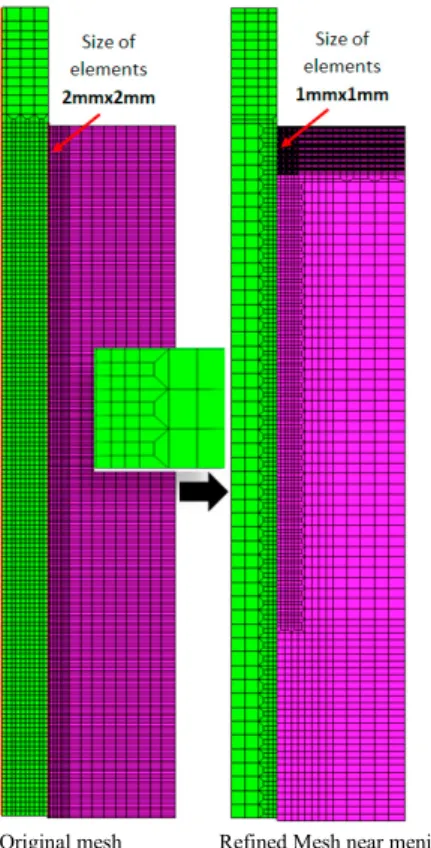
The main aim of the study is to simulate the propagation of the crack within the solidified shell due to the sticking phenomenon near the meniscus. In a first step, a single manual remeshing procedure (see Fig. 5 and Fig. 6) is performed to reduce the computation time in the next steps. Indeed, only the area near the meniscus needs to be refined to model the sticking and the addition of new liquid elements (see Fig. 5) so the mesh far from the meniscus can be coarsened. The number of degrees of freedom of the mesh presented in Figure 2 is reduced by a factor of 3. The temperature field of the old mesh on the new mesh is projected by a Matlab script (see Fig. 6).
Once a fracture happens, the finite element simulation requires the addition of new elements to model the liquid steel filling the gap between both sides of the cracked shell.
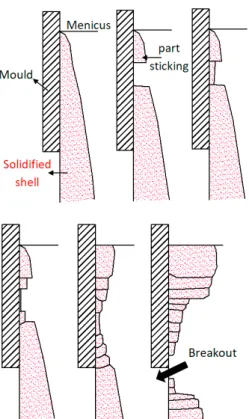
The propagation of crack due to the sticking of solid shell near meniscus is a cyclic event staggered in space and in time, it consists of 2 main steps:
1) A crack due to sticking of solid shell is formed. The gap is filled by liquid steel which is solidified and increases the area already stuck on the mold.
2) The thin, hot and weak layer just formed at the crack location will be teared again in shifted a location toward the casting direction due to the relative movements of the mould and the strand (Fig. 7).
Original mesh Refined Mesh near meniscus Fig. 5. Remeshing process with transition element (green elements for the mould, pink ones for the slab).
Fig. 6. The thermal fields in the old mesh and in the new mesh (dark red liquid, dark blue solid, color scale of Figure 3 is used).
q
Fig. 7. The propagation of a crack due to the sticking breakout phenomenon
In reality, to infiltrate the liquid slag between the copper mould and the slab, the mould is oscillating. Fig. 8 reminds the notion of oscillation. The time when the mould descends faster than the casting speed is called “negative time strip” (hatched area).
Fig.8. Description of the mould oscillation, velocity versus time curve.
The current study has developed a new remeshing procedure which specifically takes into account this phenomenon. At this stage of the research, as the stress field effect is not yet modeled, the rupture criteria is defined by the user. A crack happens when the velocity difference between the mould and the slab is maximum and generates high tension. The amplitude of the tear is constraint by the difference in relative displacement. A 2D automatic remeshing procedure is applied after each period of oscillation T (see Fig. 8) according to a methodology explained in Fig. 9.
When the mould goes up, the whole strand continues to go down. However at the meniscus level, the sticking part of the strand accompanies the mould, which explains why the solidified shell will be teared at its weakest point below the sticking part. In the developed finite element model, the initial size of the sticking part is imposed as input data, a rigid body displacement d is imposed on this part to follow mould displacement. For the 2D simulation, with an oscillation period of T (in Fig. 8, 1 second), one approaches the size of the crack for each period by:
d = Vcasting × T (4)
The new layers of elements are introduced between the sticking part and the bottom part below the crack section. The liquid steel (new elements) in direct contact with the mould solidifies quickly. The solidification time is estimated to be greater than the "Negative strip time" and lower than the period T. The effect of the duration choice can be numerically studied. In fact, the new solidified shell is mechanically weak and the next rupture location will be detected by a thermal analysis telling where the solidified shell thickness is the smallest for the next period of the simulation. Finally, the sticking piece goes up with the mould and re-tears the strand again below the old crack. Then, the liquid steel fills the crack and solidifies. The phenomenon is repeated and enables the crack to propagate.
The procedure of adding new elements has been implemented in the Lagamine code. For each new mesh, several information needs to be updated: temperature of new nodes, contact elements, boundary conditions (see Fig. 10).
Fig.9. Description of the methodology to add elements at the crack event and to follow the crack propagation
Fig. 10. New mesh following a crack event.
Currenly, the 2D thermal model is tested in order to validate the method. The continuous casting process data are as follows: temperature of the incoming steel in the mould TL=1793K;
casting speed Vcasting =1mm/s; oscillation period T=1s;
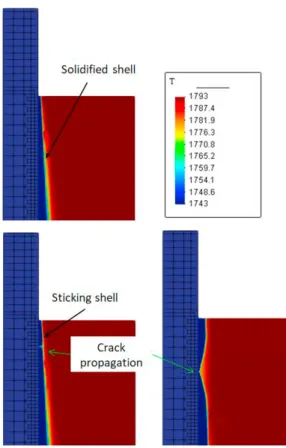
“Negative time strip” = 0,25s. Fig. 11 shows the propagation of crack due to a sticking shell. The crack propagates at half speed of the casting speed. This model helps to understand and optimize the repair procedure of the sticking breakout problem.
Fig. 11. Model finite element of sticking break out phenomenon (Temperature field K).
4. Conclusion
In the present paper, a 2D thermal finite element approach models the primary cooling of a continuous casting process. It predicts the thermal field of the strand within the mould and the thickness of the solidified steel shell.
A second thermal model is established in order to simulate the propagation of crack due to the sticking break out phenomenon. A specific remeshing procedure has been developed. The model can be used to optimize the detection procedure of mould cracks due to sticking phenomena. In future works, parametric studies of crack events will be performed to better understand this phenomenon.
Acknowledgements
As Research Director of FRS-FNRS, AM Habraken acknowledges the support of this institution. The Walloon Region, specifically the Pole Mechatech program and EBDS Engineering S.p.r.l. are thanked for their financial support of the project: ECA - Convention n° 7901.
References
[1] Weiner JH, Boley BA. Elasto-plastic thermal stresses in a solidifying body. Journal of the Mechanics and Physics of Solids 1963;11(3):145-54. [2] Tien RH, Koump V. Thermal Stresses During Solidification on Basis of
Elastic Model. Journal of Applied Mechanics 1969 Dec 1;36(4):763-7. [3] Hattel J, Hansen PN, Hansen LF. Analysis of thermal induced stresses
in die casting using a novel control volume FDM technique. 1993;585-92. [4] Lee JE, Yeo TJ, Hwan OH K, Yoon JK, Yoon US. Prediction of cracks in continuously cast steel beam blank through fully coupled analysis of fluid flow, heat transfer, and deformation behavior of a solidifying shell. Metallurgical and Materials Transactions A 2000;31(1):225-37. [5] Heinlein M, Mukherjee S, Richmond O. A boundary element method
analysis of temperature fields and stresses during solidification. Acta Mechanica 1986;59(1):59-81.
[6] Moitra A. Thermo-mechanical model of steel shell behavior in continuous slab casting University of Illinois at Urbana-Champaign; 1993. [7] Thomas B, Moitra A, Mcdavid R. Simulation of longitudinal Off-corner
depressions in continuously cast steel slabs. 23 ed; 1996.
[8] Park JK, Thomas BG, Samarasekera IV. Analysis of thermomechanical behaviour in billet casting with different mould corner radii. Ironmaking & Steelmaking 2002 Oct 1;29(5):359-75.
[9] Park J-K, Li C, Thomas BG, Samarasekera IV. Analysis of Thermo-Mechanical Behavior in Billet Casting. 60th Electric Furnace Conference, San Antonio, TX, Nov. 10-12, ISS-AIME, Warrendale, PA, 669-685, 2002. [10] Tszeng TC, Kobayashi S. Stress analysis in solidification processes: Application to continuous casting. International Journal of Machine Tools and Manufacture 1989;29(1):121-40.
[11] Boehmer JR, Funk G, Jordan M, Fett FN. Strategies for coupled analysis of thermal strain history during continuous solidification processes. Advances in Engineering Software 1998;29(7):679-97.
[12] Boehmer JR, Fett FN, Funk G. Analysis of high-temperature behaviour of solidified material within a continuous casting machine. 1993;47(4-5):683-98.
[13] Koric S, Thomas BG. Efficient thermo-mechanical model for solidification processes. Int J Numer Meth Engng 2006 Jun 18;66(12):1955-89.
[14] Zhang S, Guillemot G, Gandin CA, Bellet M. A partitioned solution algorithm for fluid flow and stress-strain computations applied to continuous casting. 2019;529:012082.
[15] Pascon F, Habraken AM . Finite element study of the effect of some local defects on the risk of transverse cracking in continuous casting of steel slabs. Computer Methods in Applied Mechanics & Engineering, 2007; 196, 2285-5599.
[16] Pascon F, Pecquet E, Zhang L, Habraken AM. Modelling of semi-continuous casting of cupro-nickel alloys. Papadrakakis, M., Onate, E., and Schrefler, B. Proceedings of the International Conference on Computational Methods for Coupled Problems in Science and Engineering; 2005.
[17] Habraken AM, Cescotto S. Contact between deformable solids, the fully coupled approach. Mathematical and Computer Modelling. 1998; 28(4-8), 153-169.