HAL Id: hal-03012785
https://hal-mines-albi.archives-ouvertes.fr/hal-03012785
Submitted on 5 Jan 2021HAL is a multi-disciplinary open access archive for the deposit and dissemination of sci-entific research documents, whether they are pub-lished or not. The documents may come from teaching and research institutions in France or abroad, or from public or private research centers.
L’archive ouverte pluridisciplinaire HAL, est destinée au dépôt et à la diffusion de documents scientifiques de niveau recherche, publiés ou non, émanant des établissements d’enseignement et de recherche français ou étrangers, des laboratoires publics ou privés.
Grain size and misorientation evolution in linear friction
welding of additively manufactured IN718 to forged
superalloy AD730™
Seyedmohammad Tabaie, Farhad Rezai-Aria, Bertrand Flipo, Mohammad
Jahazi
To cite this version:
Seyedmohammad Tabaie, Farhad Rezai-Aria, Bertrand Flipo, Mohammad Jahazi. Grain size and misorientation evolution in linear friction welding of additively manufactured IN718 to forged superalloy AD730™. Materials Characterization, Elsevier, 2021, 171, pp.1-13/110766. �10.1016/j.matchar.2020.110766�. �hal-03012785�
Grain Size and Misorientation Evolution in Linear Friction
Welding of Additively Manufactured IN718 to Forged
Superalloy AD730
TMSeyedmohammad Tabaie1a, Farhad Rézaï-Aria b, Bertrand C.D. Flipo c, Mohammad Jahazi a a Department of Mechanical Engineering, École de Technologie Supérieure (ÉTS), H3S1M7 Montreal, QC, Canada
b Institut Clément Ader (ICA), Université de Toulouse, CNRS, IMT Mines Albi, INSA, UPS, ISAE, Campus Jarlard, 81013 Albi, France
c TWI Ltd., Granta Park, Great Abington, Cambridge CB21 6AL, United Kingdom
Abstract
Selective Laser Melted (SLM) Inconel718 (IN718) superalloy was linear friction welded (LFWed) to forged AD730TM Nickel-based superalloy. Successful joints free of micro-porosity, micro-cracking, and oxides were obtained. Microstructure variations across the weld line developed during LFW were examined using different techniques, including laser confocal microscopy, scanning electron microscopy, energy dispersive spectroscopy (EDS) and electron backscatter diffraction (EBSD). The microstructure was also evaluated, particularly in terms of Grain size and misorientation changes were determined and correlated with microhardness evolution in different regions of the weld joint. The characteristics of the microstructure on both sides of the weld joint was analyzed and related to the deformation and temperature paths imposed during the LFW process. Dynamic recrystallization (DRX) occurred on both sides of the dissimilar weld line and it was found that Discontinuous DRX (DDRX) and Continuous DRX (CDRX) took place in the WZ and in the TMAZ, respectively. In order to study the influence of the starting microstructure in the LFW experiments, LFW of a homogenized SLM IN718 sample was analyzed and compared with the non-homogenized sample. A clear change in the size and grain misorientation levels of the heat and thermomechanical affected zones were observed between the two conditions. The differences were related to a greater degree of strain induced in homogenized sample and the increasing effect of the solid solution strengthening mechanism caused by a partial dissolution of the second-phase strengthening particles in the matrix.
Keywords: Additive manufacturing; Dissimilar linear friction welding; Ni-based superalloys;
Dynamic recrystallization; Misorientation; Microhardness.
1Corresponding author.
1. Introduction
LFW is a modern solid-state welding technique initially introduced for manufacturing and repairing blade integrated disks (blisks) in the compressor section of gas turbines made of titanium alloys [1]. In recent years, LFW has also been applied to the assembly of components made of Nickel (Ni)-based superalloys, as well as in many other engineering applications, ranging from automotive to agriculture, and allowing for new designs and applications [1, 2]. In addition to overcoming the disadvantages associated with mechanical assembly techniques, such as fretting fatigue and thermomechanical fatigue [3-5] observed in conventional blade-disk setups, or cracking and distortions in fusion-based welding assemblies, LFW joints are characterized by higher mechanical properties and extended component life in service [6, 7]. During the LFW process, a reciprocating movement, along with a normal pressure, is imposed on the two surfaces to be joined. The frictional force increases the temperature in a limited zone and removes surface imperfections and impurities such as oxides from the interface and allows a fresh contact between the two surfaces, which are joined in the last step by the application of a forge pressure. Therefore, the technique is ideally suited for assembling dissimilar materials tailored for specific designs and applications [1]. The thermomechanical cycle imposed during the LFW process produces three distinct zones, namely, the Weld Zone (WZ), where the highest temperatures and deformations are imposed; the thermomechanical affected zone (TMAZ), characterized by deformed grains; and the heat affected zone (HAZ), where only the heat of the welding has affected the material [1].
Additive manufacturing is of great interest for the fabrication of components and structures with complex geometries for the aerospace and power generation industries, as well as an advanced technique for component repair [8]. Selective laser melting (SLM) as a laser powder bed fusion method is a widely applied powder bed additive manufacturing process being developed as an economically viable solution for processing of Ni-based superalloy [9]. In SLM, a laser beam is directed at deposited fine layers of metal powder, which are locally and rapidly heated up to fusion, together with part of the already deposited layers, and cooled down. The process is repeated layer by layer until the desired component, for example a blade, is fabricated (called
printing) [10-12]. Gas turbine blades are known for their complex geometries and high time to
market. SLM is therefore an excellent alternative to conventional fabrication techniques as it allows achieving new designs and significantly reducing the time to market constraints [13]. Therefore, the combination of LFW and SLM as two advanced techniques could open new possibilities for both the gas turbine industry and other high value-added industries.
Very limited information is available on the dissimilar solid-state welding of superalloys and for LFW of a forged microstructure to an additively manufactured superalloy, it is actually non-existent. Even that limited information covers only forged to forged superalloys joined by Inertia Friction Welding (IFW), where a rotational movement is imposed at the interface, different from
the linear sliding movement in LFW. Huang et al. [14] welded IN718 to U720Li alloy by IFW and reported substantial microhardness differences in the HAZ and the WZ. They interpreted their results in terms of variations in grain size, diffusion of alloying elements, and different volume fractions of strengthening phases on both sides of the weld line. Muralimohan et al. [15] investigated the intermixing of the ferrite and Ni phases in the weld interface during friction welding of IN718 with SM45C steel. Senkov et al. [16] used IFW to join Mar-M247 and LSHR Ni-based superalloys. They found that Mar-M247 alloy, which has a higher strength at high temperatures, presented a larger grain size at the WZ, but the thickness of this zone was narrower as compared to that of the softer alloy LSHR [16, 17]. In addition to grain size, they reported that the level of stored energy induced by the grain rotation/misorientation compatibilities and changes in dislocations density, were significant parameters that could influence the mechanical properties of joints; the fraction of secondary phases were similarly significant parameters [18, 19].
In the present study, the LFW and SLM techniques were used to study the dissimilar welding of two superalloys with the ultimate goal of evaluating the possibility of manufacturing new generation of blisks. Specifically, the LFW of additively manufactured Inconel 718 (IN718) to forged AD730TM Ni-based superalloy is investigated. IN718 is a high strength superalloy extensively used for blade applications in gas turbines due to its good weldability and excellent resistance to cracking [20-22]. AD730TM is a Ni-based alloy recently developed by Auber & Duval Company as a new forged Ni-based superalloy for turbine disk applications, and its mechanical properties are comparable to those of other Ni-based superalloys such as Waspaloy, Udimet720 and IN718Plus [13, 14, 23-25].
2. Experimental Procedures
The as-received forged AD730TM alloy was provided by Aubert & Duval. The alloy was produced by vacuum induction melting, followed by vacuum arc remelting (VAR), and was then radially forged to produce a bar-round billet. The bar was solutionized at 1080 °C for 4 hours, followed by air cooling. Rectangular samples [37 (L: length) × 26 (W: width) × 13 (H: height) mm3] were wire-electro discharge machined (EDM) from the as-received material for LFW. The average grain size of the alloy microstructure was 41.36 ± 9.14 µm, with a γ' volume fraction of 40%. The chemical composition of the alloys is provided in Table 1.
Very similar rectangular samples [40 (L: length) × 26 (W: width) × 13 (H: height) mm3] of IN718 superalloy, were fabricated by an SLM-125HL machine at IMT-Mines Albi, France, for LFW in as-fabricated conditions. Spherical-shape alloy powders with a particle size distribution between 15 and 50 μm were used for SLM processing. The laser beam scanning orientation and the building direction were collinear with the Z-direction displacement and perpendicular to the fabrication platform. The laser beam scanning was rotated successively for 67° in each layer to reduce microstructural anisotropy. The area fraction of the porosities was measured all over the
as-SLMed IN718 specimen after SLM and was determined about 0.4% in the bottom and about 0.28 % in the top of the part. Post-fabrication chemical analysis was carried out by Atomic Emission Spectroscopy (AES). The results are reported in Table 1 and are based on an average of five measurements.
Table 1. Chemical compositions of AD730TM and SLM IN718 alloys.
Alloy Element (Wt. %)
Ni Fe Cr Co Mo W Al Ti Nb B C Zr Si
AD730-Forged Bal. 4 15.7 8.5 3.1 2.7 2.25 3.4 1.1 0.01 0.015 0.03 -
IN718-SLM Bal. 15.7 20.54 0.1 3.13 - 0.34 1.17 5.1 0.002 0.04 0.018 0.01
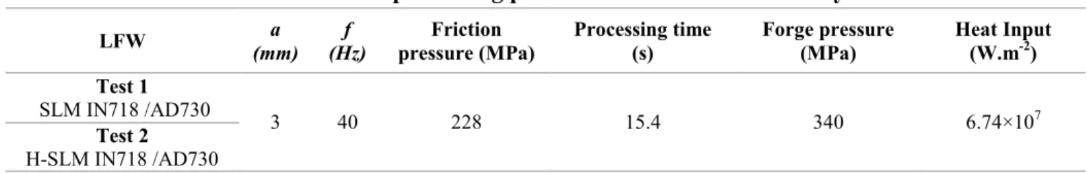
The LFW process was conducted using an FW34-E20 LFW machine at TWI, Cambridge, UK. Figure 1 shows a schematic of the LFW process, where it can be seen that the pressure was applied perpendicular to the cross-section defined by the length (L) and the width (W, i.e., area of L-W). The oscillations on the top of the SLM-IN718 samples were perpendicular to the SLM building direction and the surface in contact with the AD730TM was the surface on the top of the building direction. Table 2 and Figure 1 present the details of the LFW processing conditions. Before LFW, faying surfaces were grinded by SiC paper up to 800 grades and cleaned out by acetone to remove any oxidation and contamination. The height reduction after LFW (called axial shortening) is used as a reliable indication of the combined effects of frequency (f), oscillation amplitude (a), friction and forge pressures, and the welding time on the quality of a LFW joint [26, 27]. LFW process was carried out based on an estimation of high temperature mechanical properties of IN718 alloy and optimum welding parameters for defect free joints in AD730TM [23] were determined to be a friction pressure of 228 MPa, an oscillation frequency of 40 Hz, and an amplitude of 3 mm for the friction phase and a forge pressure of 340 MPa is applied in the last stage.
SLM-IN718 samples were used in two conditions: as-fabricated SLM condition (as-SLM IN718) and after homogenization treatment at 0011 °C for 1 hour (H-SLM IN718).
Table 2. LFW processing parameters in the current study.
LFW (mm) a (Hz) f pressure (MPa) Friction Processing time (s) Forge pressure (MPa) Heat Input (W.m-2)
Test 1
SLM IN718 /AD730 3 40 228 15.4 340 6.74×10⁷
Test 2
Figure 1. Schematic presentation of process for LFW of dissimilar welding of forged Ni-based superalloy AD730TM to as-SLM IN718 and H-SLM IN718 superalloys.
Figure 2. Linear friction welded samples: (a) SLM IN718 to AD730TM, (b) Homogenized
SLMed IN 718 (H-SLM IN718) to AD730TM alloy. The building direction (BD) in the SLM
samples is shown with a black arrow. The dashed rectangular area applies to the microstructural analysis.
After welding, to detect possible presence of porosity formed around the weld zones, X-ray Computed Tomography (XCT) by XCT Scan and an XTH-225 Nikon machine were employed. XCT scans were carried out along weld lines (Figure 2) with high resolution scanning (9 to 25 μm) from the sample edges toward the center of the joint. By changing the XCT resolutions, the full-size range of pore sizes could be seen in different positions. Data analysis was conducted using a dedicated image analysis software.
For metallographic and microstructural analyses, the welded samples were EDM-cross-sectioned perpendicular to the welding direction from the center of the sample along the longitudinal axis (the rectangular area as shown in Figure 2 (a)). The cross-sectioned samples were prepared by standard metallographic techniques for microstructure investigation, and using waterless Kalling and Marble solutions for etching. A LEXT OLS4100 laser confocal microscope was used for light microscopy (OM) and scanning electron microscopy (SEM) examinations were carried out using a Hitachi TM3000 tabletop SEM, as well as a Hitachi SU-8230 Field Emission-SEM equipped with a Bruker Electron Backscatter Diffraction (EBSD) and Quad EDS detectors. Specimens for EBSD examinations were prepared on a Buehler VibroMet™ polisher using a 0.05 μm colloidal silica suspension. Then, the specimens were ion-milled by an Ion Beam Milling System (IM 400Plus, Hitachi). To illustrate grain size variations in the weld regions, a 0.41 μm step size was selected for EBSD mapping. Because grain size variations or recrystallizations are expected to take place during LFW, a quantitative measurement of the grain size on the IN718 side was carried out using step sizes ranging between 90 nm and 0.47 μm. The finer step size of 90 nm was used for the dynamic recrystallized region close to the weld lines or WZ, and the coarser step size of 0.47 μm was used for the non-recrystallized regions (TMAZ, HAZ, and BM). In order to evaluate the grain size at each location, an average of at least 300 grains was characterized for each microstructure. The EBSD data were analyzed using Esprit software developed by Bruker, to obtain grain size and misorientation distributions, as well as for EDS analysis.
The microhardness (HV) profiles were measured on cross-sectioned LFWed samples using a Future-Tech Vickers device to evaluate the weld strength. The measurements were carried out under a load of 200 g and a dwell time of 15 s, and over a distance of approximately 3 mm from the weld interface to the base materials, to identify variations in strengths across the weld regions in both superalloys. The measurements were repeated at least five times for different distances and the average values are reported.
3. Results and Discussion
3.1. Microstructural evolutions across the weld Line
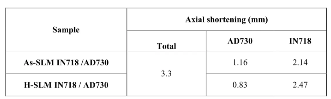
Figure 3 (a) shows the XCT-Scan of the as-SLM IN718/AD730TM LFWed joint. A defect-free joint is clearly visible, showing no presence of oxides or cavities. Figure 3(a & b) show a macroscopic view of the weld joint, with no oxides or gap visible at the interface. It is also important to note that the flash shape and amount are not symmetrical and identical for the two materials, which indicates that the material response to the imposed LFW thermomechanical cycle had been different on each side of the joint. For instance, as reported in Table 3, the axial shortening from the IN718 side was thicker than that from the AD730TM side for both starting IN718 microstructures (i.e., as-SLM or H-SLM). It should be also noted that the axial shortening (3.3 mm) was identical for both starting microstructures. The higher axial shortening on the
IN718 alloy side can be explained by the difference in high-temperature mechanical properties of the two alloys as the strength of as-printed IN718 dropped more rapidly than that of AD730TM alloy in the high-temperature process when compression force was applied. This behavior could be attributable to the difference in some of the strengthening phases between the two alloys. Indeed, the matrix of AD730TM is solid solution-hardened by W and Co (elements absent in IN718), which may contribute to the maintenance of a higher resistances and therefore to a resistance loss for IN718 at these temperatures. Another possible source could be the difference in thermal capacity between the two alloys resulting in higher heat conduction in IN718 as compared to AD730TM. Furthermore, the distance from the weld line affected by the heat seems to be greater, as will be discussed in sections 3.2 and 3.4, which cover respectively grain size evolution and hardness.
In Figure 3b, the magnified view of the weld interface (as indicated by dashed lines in Figure 3a) is reported, with the geometry of the weld line and of the different zones on both sides of the joint identified. As illustrated, the microstructure of the WZ on the AD730TM side is very smooth, with only a few large particles still visible in the WZ. The very smooth nature of the interface indicates a significant dissolution of second-phase particles, which are probably γ'. It must be noted that, the melt pool boundaries as well as the columnar grains in the TMAZ and the WZ of SLM IN718 were eliminated due to the thermomechanical cycle applied during the LFW process.
Figure 3. (a) XCT-Scan image from weld area, and (b) OM image of the weld interface rotated counterclockwise relative to (a) shows a crack free weld area. The black particles in
the WZ are MC-type carbides.
The temperature on the weld line reported for these two alloys could be in the range of 1200-1250 °C [13, 17, 18, 23]. At these temperatures, the main strengthening precipitates γ״, γ׳ and/or δ phases in as-SLM IN718 as well as γ׳ particles in the AD730TM superalloy are expected to be completely dissolved. Since the strengthening precipitates have been dissolved, it is reasonable to assume that each part will exhibit very low flow stress and that the material will be ejected into the flash. As a result, different macro- and microstructural characteristics are to be expected near the weld line region, on either side of the weld. Considering that the dissolution temperature of the strengthening phases in IN718 (γ״=930°C, γ׳ =970°C, and δ=1020°C) [28, 29] are lower than in AD730TM (γ׳=1200°C) [25, 30], more material will be ejected from the weld region of as-SLM-IN718 (and H-SLM) into the flash at a lower temperature than for AD730TM.
Table 3. Axial shortening of samples after forging stage in LFW.
Sample Axial shortening (mm)
Total AD730 IN718
As-SLM IN718 /AD730
3.3 1.16 2.14
H-SLM IN718 / AD730 0.83 2.47
3.2.Grain size evolution
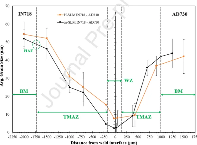
Grain size variations across the weld interface were investigated by electron backscatter diffraction (EBSD) and FE-SEM. Figure 4 shows the grain size distribution in different regions of the weld area. The average grain size evolution from the weld interface to the base metal was measured according to the ASTM: E11 2-12 standard.
EBSD mapping (Figure 5) shows dynamic recrystallization (DRX) on both sides of the weld, including fully (at the WZ) and partially (at the TMAZ) recrystallized zones. For the as-SLM IN718 material, grains were refined from 51.8 µm in the base metal (BM) to 2.25 µm in the WZ. A similar trend was observed for the H-SLM IN718 samples, where it was found that the grain size decreased from 67 µm to 7.54 µm from the BM to the weld line. On the AD730TM side, the 45 µm grain size in the BM was reduced to 2.5 µm in the WZ of the joint with the as-SLM IN718 (7.9 µm in the joint with H-SLM sample), further confirming the significant grain size reduction on both sides of the dissimilar weld joint.
In the TMAZ, which is the zone adjacent to the WZ, the grain size became progressively larger over a distance of about 1500 µm on the IN718 side and 1000 µm on the AD730TM side,
indicating that the kinetics of recrystallization on the AD730TM side were significantly slower. This grain size evolution indicates that applying an linear oscillation movement and a friction force along with compression stress (forging stage) can modify significantly the size and crystallographic orientations of the original grains in the initial microstructure in the WZ and the TMAZ by recrystallization mechanisms, thanks to severe plastic deformation at high temperature within the weld interface regions [31].
In the as-SLM IN718 part between the TMAZ and the BM, the HAZ with a thickness ranging from 20-60 µm was observed (cannot be seen in Figure 3b), and contained some blocky zones in the middle of columnar grains as reported also by [32]. According to the latter’s report, this zone was only affected by a high heating and cooling rate during the LFW process. In the HAZ, not only was there a partial dissolution of Laves particles, but delta and γʺ phases were also able to remain in the blocky zones. However, the HAZ was not observed in the AD730TM alloy, just as was the case in a similar investigation for the LFW of this alloy by Masoumi et al. [23].
Figure 4. Grain size at various locations from the weld interface in the LFW of SLM and H-SLM IN718 to AD730TM.
Figure 5. (a), (b) EBSD grain map and inverse pole figure (IPF) map from the weld line for LFW of SLM IN718 and H-SLM IN718 to AD730TM alloy, respectively. (c) and (d) SEM
micrographs from the weld line for LFW of SLM IN718 and H-SLM IN718 to AD730TM
alloy, respectively. Laves particles on IN718 side and the GBB on AD730TM side are
illustrated by yellow circles.
The heat input (HI) in the friction phase could be estimated for the selected LFW process parameters by the following equation, as also reported by others [23, 33, 34]:
Eq. (1)
where μ is the friction coefficient, and PFr are the rubbing velocity (plastic deformation due to
the fraction) and friction pressure (220 MPa), respectively. A fixed rubbing velocity of 480 mm·s-1 was considered and the friction coefficient was taken equal to 0.6, as reported in the literature [23, 29, 33]. On the basis of the above values, a heat input of 6.74 × 10⁷ W.m-2 was calculated for the present study. Furthermore, using an analytical procedure reported by Masoumi et al. [23], and considering the effect of adiabatic heating by mechanical deformation (
∫ [35], the maximum temperatures at the interface of similar friction welding were estimated to be about 1220°C for the SLM IN718 and 1250°C for the AD730TM alloy during the LFW process. Therefore, the temperature at the interface of the dissimilar weld (SLM IN718 to AD730TM) is expected to fall within this interval (1220-1250°C).
Since exposure to such high temperatures, severe plastic deformation, and rapid cooling induces significant changes in the microstructure across the weld, the occurrence of dynamic recrystallization (DRX) is noticeable, as shown in Figure 5. DRX has been frequently observed during hot deformation processes in low stacking fault energy materials such as Ni-based superalloys (e.g., AD730TM and IN718), where the recovery or dynamic recovery (DRV) process is slow and the material retains large amounts of thermomechanically induced stored energy [31, 36-39] (1100 °C for IN 718 [36]). During the DRV process, thanks to the combination of generated stress and high temperature, the dislocations are sufficiently activated, leading to a rearrangement of the edge dislocations of the same symbol in a small angle of the boundary along the direction perpendicular to the sliding surface, resulting in the formation of subgrains [40]. These subgrains become the nuclei of recrystallization and the newly formed grains grow under the high temperature. However, in the present case, as the heating and cooling rates of the LFW process were very fast, the growth of the recrystallized grains was restricted, leading to the formation of fine grains in the weld zone, as shown in Figure 5 (a & b).
Regarding the characteristics of recrystallized grains in the WZ, the DRX that occurred in this zone could be categorized as DDRX. Lin et al. [41, 42] reported that dominant recrystallization mechanism was DDRX for the GH4169 superalloy (as same as IN718), and CDRX had a minor contribution to the overall recrystallization process. The DDRX process is based on the nucleation of new grains through a mechanism called grain boundary bulging (GBB). The presence of wavy grain boundaries and grains with serrated edges in the microstructure indicates that GBB has taken place. GBB occurs on the initial high angle grain boundaries (HAGBs) which are characterized with high dislocation density [36, 39]. Illustrative examples are marked by arrows in Figure 5 (c & d). When the accumulated difference in strain energy in the HAGB reaches a critical value, the DRX nucleus (marked by circles in Figures 5 c & d) can grow and result in the migration of the grain boundary.
As the grain boundary moves (driven by the difference in the dislocation density of the recrystallized and non-recrystallized grains), the dislocation density behind the boundary is reduced to near-zero values (as a result of the recrystallization process). However, with
continued straining, the dislocation density behind the moving boundary increases, approaching that of the non-recrystallized material, and thus, the driving force for continued grain growth decreases. In addition, the bulges along the original grain boundaries can be the actual nucleation sites for DRX as reported in [33]. Finally, the nucleation of the DRX can also occur at a triple grain boundaries junction because the high strain concentrations at these junctions stimulate DRX nucleation [33, 43].
As mentioned above, LFW thermomechanical parameters (i.e., temperature, strain, and strain rate) were lower in the TMAZ than in the WZ. They were therefore less effective in promoting the recrystallization. Fully recrystallized grains were formed in the WZ, while only partial recrystallization was observed in the TMAZ. Furthermore, the grains in the TMAZ were highly deformed along the linear oscillation direction, while their average grain size in this area was similar to that of the BM. However, the TMAZ grains did not show the very intense deformed morphology as reported in TMAZ of LFWed Titanium alloys [44]. This could be related to the high plastic flow stresses of superalloys at high temperatures.
The EBSD map of low angle grain boundary misorientation (LAGBs, 2°-15°) and high angle grain boundaries (HAGBs, >15°) of different weld regions is shown in Figure 6. The figure also provides an insight into the evolution of the microstructure at different locations from the weld line by presenting the evolution of the LAGBs, HAGBs, and Ʃ3 twin boundaries on both sides of the joint. The fine grains in the WZ are characterized by a very low scattering in misorientation. The WZ is dominated by HAGBs with a percentage of 96.5 and 95.8% on both sides of as-SLM-IN718 and AD730TM; respectively, which indicates that extensive recrystallization occurred in this zone. This result is consistent with the SEM analysis, as mentioned above. The proportion of the LAGBs in the TMAZ increases as compared to the WZ, which is more obvious on the IN718 side (both as-SLM and H-SLM). The higher proportion of LAGBs in the TMAZ of IN718 alloy is indicative of possibly different recrystallization mechanisms as compared to AD730TM.
In AD730TM alloy, at approximately 1 mm from the weld line, LAGBs start to develop within the parent grains or near the parent grain boundaries. Therefore, this zone could be considered as the outer edge of the TMAZ. The LAGBs have very low misorientations, and the HAGB fraction in this region is close to that of BM. Closer to the weld zone, LAGBs are observed within the most of the original grains, and are frequently concentrated close to the original grain boundaries. Furthermore, according to the coincident site lattice (CSL) model, the Σ3 boundaries, as a type of HAGBs (primary twins are a subset of this boundary [45]), appear to have been transformed into random boundaries as evidenced by an increase in their fraction from 48.7% to 86.4% (from the WZ to the BM). This increase in the fraction of twin boundaries has been attributed not only to the strain-induced crystallographic rotations forming the mechanical twins in the surrounding matrix, but also to the generated annealing twins. These twins are deviated from the ideal Σ3 misorientation because of cyclic thermo-mechanical loading applied during LFW [24].
Figure 7 shows the EBSD map of the welded joint. The microstructure of as-SLM IN718 was mainly composed of coarse columnar grains elongated in the building direction in the BM zone (Figure 7a). The grains contained certain number of dendrites having the same growth direction. These dendrites were separated by LAGBs, while adjacent grains were separated by HAGBs. In addition, the columnar grains had higher amounts of LAGBs than the TMAZ and the WZ. In the TMAZ, the microstructure was composed of both columnar and fine grains (Figure 7b & c). Moreover, both fine and elongated grains were observed in the TMAZ making HAGB with the adjacent grains. In the BM, HAZ and in some grains at the end of the TMAZ, coarse columnar grains were observed. The above findings are in agreement with those reported by Tucho et al. [46] and Huang et al. [47].
However, in the WZ and the TMAZ, the columnar grains were recrystallized due to the high temperature (1050-1250°C) and high strain rate (3.5-1000 s-1). As can be observed in Figures 6 and 7, the microstructure in the TMAZ transformed progressively from the LAGBs into high HAGBs during hot deformation. This evolution, which was manifested by the formation of finer grains without the nucleation of fine grains at the interfaces, is characteristic of the occurrence of continuous dynamic recrystallization (CDRX) [48, 49]. CDRX by lattice rotation near grain boundaries (LRGB), as well as sheared micro-bands (elongated grains induced by shearing force during the friction movements) could be the governing mechanisms responsible for CDRX in this zone.
A large number of new Σ3 boundaries were obtained in the newly formed DRX grains, whose fraction increases with the increasing strain. In other words, as the cumulative cyclic strain increases, there is a decrease in the total LAGBs fraction, and a simultaneous increase in the fraction of HAGBs, many of which have a Σ3 twin relationship. However, in the WZ, the Σ3 twin relationship is lower than in the TMAZ, probably due to the higher deformation temperature and removal of the twins in the WZ. It was reported by Zhang et al. [45, 50] that a concomitant rotation of grains during high-temperature deformation of Ni-based superalloys continuously changed the orientation of original twin boundaries, and that most of the original Σ3 boundaries lost their Σ3 relationships at relatively low strain, leading to a reduction of Σ3 boundary fractions. A similar trend is observed in the present work, where as reported in Figure 6, the fraction of Σ3 boundaries was reduced from 63 to 30.5% near to the BM zone (1500 µm from weld line) of as-SLM and H-SLM IN718 after the LFW process.
The proportion of the LAGBs in different regions could be an indication of the difference in deformation conditions between BM and other regions. However, as reported in Figure 6, the LAGB fraction in the TMAZ of the SLM parts was higher than in the WZ. This could be due to the lower deformation temperature and lower plastic strain rate that the material experiences in the TMAZ than in the WZ, which leads to incomplete DRX in the TMAZ. Hence, the percentage of HAGBs in the TMAZ tends to decrease.
Figure 6. Variation of HAGB, LAGB, and Ʃ3 twin boundaries from the weld interface to the BM on both sides in LFWed samples: (a) as-SLM IN718-AD730TM and (b) H-SLM
IN718-AD730TM.
In the WZ, where the strain is the highest, the growth of DRX grains is promoted, and there is a significant decrease in the dislocation substructure arrangements, while the fraction of HAGBs increases. At small strain levels, in the TMAZ, the stored deformation energy is relatively low, and insufficient for the annihilation and rearrangement of most of the dislocation substructures. So, the fraction of HAGBs in the TMAZ is less than in the WZ (Figure 6). With increasing strain, the high dislocation network is gradually converted to substructures, and then transformed into DRX grains [41, 51]. The EBSD results reported in Figures 5 and 7 appear to confirm the above analysis in both as-SLM and H-SLM IN718.
The plastic deformation induced by the LFW process results in the introduction and movement of dislocations [41, 52]. Huang and Loge [49] studied the generation and reorganization of dislocation networks during dynamic recrystallization. They reported that dislocations are rapidly generated during the early stages of hot deformation, resulting in the formation of a high dislocation density network. Comparing changes in the TMAZ of as-SLM IN718 with AD730TM, in Figure 5, it can be seen that microstructure of the as-SLM IN718 has a higher sensitivity to process parameters (e.g., strain and strain rate) than that of AD730TM.
Figure 7. EBSD grain map in the as-SLM IN718 after the LFW to AD730TM alloy: (a) in the BM zone, (b) in the BM+TMAZ, (c) in the TMAZ, and (d) in the TMAZ+WZ. IPF map
The third factor that could influence the grain size evolution on each side of the dissimilar joint is the strain rate during the LFW process, which reaches its highest value during the forge phase. The strain rate can be estimated using an average velocity (a × f) over the total length (l) (as reported in Table 2) [8, 53]:
̇
Eq. (2)
Turner et al. [54] estimated the strain rates for different amplitudes of oscillations using finite element modeling (FEM) for LFW of Ti-6Al-4V alloy. According to their estimation, the strain rate could be in the range of 1000-1500 s-1 in the weld area. Chamanfar et al. [53] modeled the grain size evolution during LFW of Waspaloy and reported that the strain rate in the weld area was in the range of 1520 s-1. However, the model provided by Masoumi et al. [23], mostly based on equation (2), predicts a strain rate in the 3.85-10 s-1 range for LFW of AD730TM alloy. The grain refinement could be associated with the occurrence of DRX, according to Zener-Hollomon equations ̇ ( ) , where Z is the Zener-Hollomon parameter, Q is the activation energy for dynamic recrystallization, ̇ is strain rate, T is the temperature (in Kelvin) and A and β are material constants. These equations show that recrystallization is accelerated at higher temperatures [23, 55]. Mostafa et al. [56] reported that, in SLM IN718, the high strain rate (0.1 and 1 s-1) observed is associated with the occurrence of very localized DRX, followed by hardening and short-range ordering of solute atoms (Nb, Al, and Ti). Moreover, they noted that the effect of the strain rate was greater than that of the temperature. However, in the present study, the higher strain rate (e.g., LFW conditions), in addition to a very short process time (15 s) and high temperature (higher than the dissolution temperature of strengthening phases), did not lead to a significant change in the grain size (grain coarsening) probably due to the occurrence of meta-dynamic recrystallization (MDRX), static recrystallization (SRX), and grain growth. In the present case it appears that the SLM-IN718 is more influenced by the strain rate applied in the process and showed more recrystallization as compared with AD730TM.
3.3.Misorientation
The misorientation angles were defined as <15°C for LAGBs and above 15° for HAGBs. Figure 8 provides the average of misorientation angles value (based on the color bar) between all pairs of neighbouring points in the grains. The color-coded map is shown at the bottom, with the blue and red colors representing the minimum and maximum misorientation levels, respectively. The grain reference misorientation deviation (GROD) was used to analyze the misorientation induced by the dislocation arrangements in the deformed and non-deformed grains after the LFW. This map is a parameter that was calculated from the EBSD data to assess misorientation distribution (according to the strain distribution), as well as the dislocation density. The GROD shows the orientation deviation between a reference point in a grain and all other points within the grain, which can reflect and quantify the dislocation density in the deformed part in each zone. The
evolution of the misorientation angle or GROD is closely associated with the evolution of DRX, and ultimately, with the volume fraction of DRX grains. It must be noted that, recrystallized and non-recrystallized grains have different dislocation densities, which induce different intragranular misorientation levels and can also be analyzed by Kernel Average Misorientation (KAM) [57].
Figure 8a represents the misorientation map of the BM region of the as-SLM samples. The misorientation in the BM regions after LFW represents the misorientation in the initial microstructure of as-SLM and H-SLM IN718. It should be noted that this region is considered as not having been affected by the thermomechanical cycle of the LFW process. The results show that higher strains or dislocation densities were concentrated near the grain boundaries (GBs) in the as-built IN718 (Figure 8a), the BM of AD730TM (Figure 8e) and the TMAZs (Figure 8 b, c, & d) in weldment. Figure 8 (a & e) show many grains with significant levels of intragranular misorientation, indicating that high geometrically necessary dislocation constitutes the main fraction of LAGBs and twin boundaries. In Figure 8c, most grains are blue in color, and are likely recrystallized. There are isolated grains with less intragranular misorientation than the others. These observations are in agreement with those of Li et al. [58], who associated the isolated grains to the presence of Laves phases in GBs providing heterogeneous local misorientation distributions.
As reported in Figure 8, the misorientation decreased from the BM (Figure 8 (a and e)) to the WZ (Figure 8 (c)) indicating the decrease of subgrains sizes and the increased extent of dynamic recrystallization. The Figure also shows that the distribution of misorientation angles on both sides was affected by both temperature and strain rate. These findings are in agreement with those reported by Salishchev et al. [59] who found that the misorientation angle increased with an increase of the strain rate. Figures 8 b, c, & d, show that the misorientation angle in as-SLM IN718 is more sensitive to deformation conditions (e.g., temperature, strain, and strain rate) than AD730TM alloy.
Figure 8. Local misorientation (LM) or average misorientation maps of the analyzed areas from the BM region in the as-SLM IN718 toward the BM region in AD730TM after LFW.
(a) and (b) are the BM and the TMAZ on the side of as-SLM IN718, respectively. (c) is the weld line and the WZ on both sides. (d) and (e) are the TMAZ and the BM on the side of
AD730TM.
3.3.1. Effect of recrystallization on misorientation
The evolution of substructures during hot deformation under LFW can be evaluated by the changes in the to-point (short-range local) misorientations inside the grains and the point-to-origin misorientations between the non-deformed and deformed grains generated by cumulative plastic shear straining (long-range change in shape or morphology of grains). The cumulative misorientations both along the original grain boundaries and within the grains increase when the deformation temperature decreases. This process took place from the WZ toward the BM (from Figure 8c to 8a and 8e). This evolution of the substructure could be related to the dislocation motion and the rotation of subgrains, which intensifies when the temperature increases. Lin et al. [51] reported that the local misorientation hardly exceeds 5°, and the variations of local misorientation with deformation temperature are limited. This indicates that the misorientation gradient is relatively steady within grains and slightly sensitive to deformation and temperature. However, the above EBSD analysis revealed that the AD730TM superalloy was free of subgrain micro-structuring, while the as-SLM IN718 superalloy was composed of HAGBs and a larger fraction of subgrain boundaries. The large fraction of HAGB results in higher instability of the microstructure, as also reported in [60].
In the WZ, of both AD730TM and SLM IN718 sides, grains have lower intragranular misorientations and dislocation densities, illustrating that the occurrence of DRX rapidly diminished dislocation entanglements and reduced the dislocation density, as also reported in [61, 62]. Conversely, the old grains (in the BM) and the growing nuclei which may readily increase in misorientation to become a new DRX grain (in the TMAZ) have higher GROD values and dislocation accumulation. Under these conditions, the DRX would be initiated once the critical dislocation density is attained in the higher GROD regions [45]. Meanwhile, the higher dislocation density manifested by higher misorientation near the deformed grains, as shown in Figure 8 (b, c, & d) indicates that new DDRX grains have been formed, mainly along the deformed grain boundaries. By easy cyclic slipping or climbing, dislocations can move towards the newly formed grain boundaries which act as sinks. The DRX would be triggered, once the critical dislocation density is attained in the higher GROD regions [45].
Meanwhile, as shown in Figure 8, a higher dislocation density, manifested by higher misorientations, can be observed near the grain boundaries of the deformed grains. This indicates that new DDRX is mainly an intergranular driven phenomena and mechanisms. Huang et al. [14] measured the level of plastic deformation stored in a dissimilar weld of two superalloys by
analyzing the stored energy across the weld line. They found that the stored energy is proportional to the boundary misorientation and the HAGB energy while it has an inverse relationship with the level of misorientation at which a boundary is considered to be an HAGB. In the present work, it was found that the WZ region which contained refined grains by recrystallization, had the lowest level of the stored energy indicating that the material was sufficiently hot enough to be readily plastically deformed during LFW and to recrystallize. In the TMAZ , both AD730TM and SLM IN718, were exposed to lower deformation rates compared to the WZ, which delays the accumulation of the plastic strain for triggering the DRX [63]. In addition, as reported by Huang et al. [14] and [39, 64] the presence of secondary-phase particles (Laves phase in SLM IN718 and γ׳ phase in AD730TM) in the TMAZ could hinder boundary migration, due to the Smith-Zener pinning effect. As a result of the above processes the dislocation density increases in the TMAZ and produces high degree of misorientation within the grains in this region as reported in Figure 8.
3.4. Microhardness
Figure 9 shows microhardness variations across the weld line as a function of the axial position. The BMs in AD730TM, as-SLM IN718, and H-SLM IN718 superalloys have average microhardness values of 393, 340, and 275 Vickers, respectively. The hardness values on the as-SLM IN718 side exhibited a decreasing trend, changing from 281 ± 9 HV at the -500 μm location to 236 ± 4 HV at the weld interface, and the lowest hardness value (236 HV) was observed at ~115 μm from the weld interface.
In the H-SLM IN718 specimen, the lowest hardness value, 234 HV, was measured at 300 μm from the weld interface. The measured hardness on the side of AD730TM increased from 364 ± 11 HV at the +1000 μm location to 443 ± 7 HV at the weld interface. The highest hardness value of 443 HV was found at 85 μm from the weld interface while in the case of LFWed joint with H-SLM IN718, the highest hardness of AD730TM was 428 ± 5.7 HV at ~ 60 μm from the WZ. Figure 9 also shows that AD730TM displays a strain hardening behavior while IN718 alloy (as-SLM or H-(as-SLM) strain softening. These findings are in agreement with those reported by other authors on dissimilar solid-state welding of IN718 to an alloy with higher strength [7, 17, 18]. It must also be noted that in all welded joints, the strengthening phases were found to be completely dissolved in the WZ. This means that no precipitation hardening is expected in this region and therefore, the observed hardness variation in the WZ can be attributed to grain size changes.
On the AD730TM side, the hardness decreased from the WZ toward the TMAZ (until ~ 1000 μm) and then increased towards the BM up to 393 ± 4.5 HV. Though this trend was similar whether as-SLM or H-SLM IN718 was used for welding; however, the hardness drop in the TMAZ was
lower (362 ± 8 HV) in the joint with as-SLM than in the joint with H-SLM IN718 (390 ± 13 HV).
On the IN718 side, interestingly, after the TMAZ, two different behaviors were observed: In the as-SLM condition, the hardness continuously increased from the WZ (236 ± 4 HV) to the TMAZ (281 ± 9 HV), and then up to the BM to reach 341 ± 8 HV. In the case of H-SLM material, after an initial increase of 234 HV over a 300 μm distance from the weld line, the hardness remained nearly stable through the TMAZ and into the BM. As shown in Figure 9, close to the BM in the as-SLM IN718, the hardness increases in the HAZ in a thin layer (20-60 μm), and then decreases again toward the BM.
The decrease in hardness in the BM of the H-SLM sample is probably due to the dissolution of secondary phases such as Laves, γʹ, γʺ, and δ during the homogenization before welding [65, 66]. This decline could also be attributed to the columnar grains that tend to grow and change in orientation to form an equiaxed texture [67] as also reported by Gargani et al. [66]. They reported that grain coarsening during homogenization had a detrimental effect on the strength and hardness of AMed IN718. In this study, both factors seem to have contributed to the evolution of the hardness.
Figures 4 and 9 show that the γ grain size and hardness were decreased ~ 79% and ~20%; respectively, over a distance between ~ 250 µm and ~ 350 µm from the weld interface on the IN718 sides of the weld joint (either as-SLM or H-SLM). In contrast, in the case of AD730TM, and for both welds, the yield strength and hardness increased with decreasing the grain size, in accordance with the well-known Hall-Petch relationship. These results indicate that other microstructural features such as the grain size, solid solution strengthening in matrix, misorientation or pile-up dislocations, and precipitates, are contributing to the hardness evolution as will be discussed below.
The grain size evolution in the weld area is a function of the temperature and strain rate experienced by the material during LFW. Therefore, the initial grain size and mechanical properties of the alloy during the LFW process will influence the analysis of the progressive grain refinement by increasing axial shortening, which affect the final hardness. As shown in Figure 9, the highest hardness is in the WZ of AD730TM. Considering that the main strengthening phase γʹ was dissolved in this zone during LFW [13, 23], the increase in strength could only come from grain refinement. Nevertheless, in the TMAZ, the hardness in the AD730TM/H-SLM joint is higher than that in the AD730TM/as-SLM IN718 joint. This could be related to the smaller axial shortening (Table 3) obtained in AD730TM when H-SLM material is used, as less deformation and heat are needed to dissolve the secondary phases (e.g., primary γʹ particles) [13, 23, 53, 68]. It must be emphasized that, although the grain size increased after the TMAZ and towards the BM (Figure 4), the hardness is higher in the BM than in the TMAZ. This finding indicates that the hardness is less affected by the temperature and deformation (strain and strain rate) where secondary phases (primary, secondary, and tertiary γʹ) could remain undissolved during the LFW process.
In contrast to the AD730TM, as illustrated in Figure 9, the lowest hardness was measured in the WZ of as-SLM and H-SLM IN718 samples. This observation could be explained in terms of the selected LFW parameters for dissimilar welding. Indeed, due to the high temperature (1200-1250°C) generated in the WZ during the LFW, the microstructure could be homogenized. As a result, the dendritic microstructure in the as-SLM IN718 and all the secondary and precipitation hardening phases (in as-SLM and H-SLM conditions) are expected to be dissolved completely. This behavior shows that the mechanical properties, specifically hardness, were significantly affected by precipitation hardening phases. The obtained results are in agreement with those reported by Ye et al. [18], who, in a recent publication, studied the LFW of IN718 to IN713LC and observed a similar trend for the hardness evolution.
In the TMAZ, the hardness in the as-SLM and H-SLM IN718 are very similar, despite the fact that all secondary and precipitation hardening phases were dissolved during the homogenization process in the H-SLM. As a result of this dissolution, it is expected that the constitutional elements of the secondary phases (e.g., Ni, Mo, Al, and Ti) that diffused to the matrix, slightly increased the hardness by the solid solution strengthening [69, 70]. Furthermore, as noted in
section 3.3, the fraction and severity of misorientation in H-SLM were higher than in the as-SLM condition, thus indicating that the differences observed in the misorientations between the two initials conditions of the IN718 material did not affect the hardness level in the TMAZ. Based on the above analysis, it could be said that the secondary phases, the solid solution, strain, and grain size affect the hardness in the TMAZ.
In the as-SLM IN718, in the narrow HAZ, between the TMAZ and the BM, the hardness increased as compared to the BM. This is due to the partial dissolution of Laves phase, the diffusion of Nb and Mo to the matrix (solid solution), and the remaining strengthening phases (γʺ and δ) in the blocky zones as also reported by [32].
In the BM zone, secondary precipitates such as Laves phase plus γʹ, γʺ, and δ phases are present in the microstructure [28]. Therefore, on the as-SLM IN718 side as the distance is increased from the weld line the hardness increases continuously until reaching that of the base metal. In the case of the H-SLM IN718 samples, all these phases were dissolved during homogenization, which in addition to producing larger grains, reduced the hardness.
4. Conclusions
In the present study, the linear friction welding method was applied to weld as-SLM and homogenized SLM IN718 (H-SLM) samples to foraged and treated AD730TM Ni-based superalloy. The evolution of the microstructure and microhardness were analyzed and discussed before and after the welding process in all regions. The main findings are:
1- Compared to AD730TM superalloy, larger TMAZ is observed on both as-SLM and H-SLM IN718 sides, which is due to the lower strength of as-H-SLM and H-H-SLM IN718 at high temperatures.
2- DDRX occurred as a dominant grain refinement mechanism in the WZ while CDRX was the dominant recrystallization mechanism in the TMAZ in the as-SLM or H-SLM IN718 superalloy. In contrast, for the AD730TM superalloy, DDRX was the only grain refinement mechanism for both the WZ and the TMAZ.
3- Grain refinement was the main mechanism in increasing the hardness of AD730TM alloy in the WZ despite the dissolution of the secondary phases.
4- Hardness decreased in the WZ of both as-SLM and H-SLM IN718. This behavior was related to the lower misorientation and the dissolution of secondary phases that neutralize the effect of grain refinement.
5- Although the hardness of the as-SLM IN718 part is generally higher than that of the H-SLM part, it was approximately the same in the TMAZ. This is due to the higher effect of solid solution strengthening in the H-SLM material and the resulting higher strains (e.g., more misorientation) induced during welding.
The authors are grateful for the support from the Natural Sciences and Engineering Research Council of Canada (NSERC) 2018-03889 through a Discovery Grant. Thanks to Mr. Adrien Lieurey (IMT-Mines Albi ICA - site Albi) for his involvement and fabrication of SLM parts. Thanks also go to Aubert & Duval Co. for providing forged AD730TM superalloy, and to TWI Ltd., for carrying out the LFW of the samples. Technical support provided by Dr. Mohammad Saadati for microscopic experiments is gratefully acknowledged.
References:
[1] A. Chamanfar, M. Jahazi, J. Cormier, A Review on Inertia and Linear Friction Welding of Ni-Based Superalloys, Metallurgical and Materials Transactions A, 46, (4), (2015), 1639-1669. 10.1007/s11661-015-2752-4.
[2] T.J. Ma, L.F. Tang, W.Y. Li, Y. Zhang, Y. Xiao, A. Vairis, Linear friction welding of a solid-solution strengthened Ni-based superalloy: Microstructure evolution and mechanical properties studies, Journal of Manufacturing Processes, 34, (2018), 442-450. 10.1016/j.jmapro.2018.06.011.
[3] N.K. Arakere, G. Swanson, Fretting Stresses in Single Crystal Superalloy Turbine Blade Attachments, Journal of Tribology, 123, (2), (2001), 413-423. 10.1115/1.1308032.
[4] L. Li, K. He, S. Sun, W. Yang, Z. Yue, H. Wan, High-Temperature Friction and Wear Features of Nickel-Based Single Crystal Superalloy, Tribology Letters, 68, (1), (2020), 10.1007/s11249-020-1266-4.
[5] R. Cortés, N.K. Rodríguez, R.R. Ambriz, V.H. López, A. Ruiz, D. Jaramillo, Fatigue and crack growth behavior of Inconel 718–AL6XN dissimilar welds, Materials Science and Engineering: A, 745, (2019), 20-30. 10.1016/j.msea.2018.12.087.
[6] T. Homma, H. Takano, T. Ozaki, Nanostructural analysis of welded Ti–6Al–4V by linear friction welding applied for blisk assemblies, Materialia, 5, (2019), 10.1016/j.mtla.2018.11.023. [7] B. Gan, H. Murakami, R. Maass, L. Meza, J.R. Greer, T. Ohmura, S. Tin, Nanoindentation and nano-compression testing of Ni3Al precipitates, Superalloys 2012, (2012), 83-91. 10.1002/9781118516430.ch9.
[8] A. Vairis, M. Frost, High frequency linear friction welding of a titanium alloy, Wear, 217, (1), (1998), 117-131. 10.1016/s0043-1648(98)00145-8.
[9] M.M. Attallah, R. Jennings, X. Wang, L.N. Carter, Additive manufacturing of Ni-based superalloys: The outstanding issues, MRS Bulletin, 41, (10), (2016), 758-764. 10.1557/mrs.2016.211.
[10] Q. Jia, D. Gu, Selective laser melting additive manufacturing of Inconel 718 superalloy parts: Densification, microstructure and properties, Journal of Alloys and Compounds, 585, (2014), 713-721. 10.1016/j.jallcom.2013.09.171.
[11] A. Hariharan, L. Lu, J. Risse, A. Kostka, B. Gault, E.A. Jägle, D. Raabe, Misorientation-dependent solute enrichment at interfaces and its contribution to defect formation mechanisms during laser additive manufacturing of superalloys, Physical Review Materials, 3, (12), (2019), 10.1103/PhysRevMaterials.3.123602.
[12] M. Balbaa, S. Mekhiel, M. Elbestawi, J. McIsaac, On selective laser melting of Inconel 718: Densification, surface roughness, and residual stresses, Materials & Design, 193, (2020), 10.1016/j.matdes.2020.108818.
[13] F. Masoumi, D. Shahriari, M. Jahazi, J. Cormier, B.C.D. Flipo, On the Occurrence of Liquation During Linear Friction Welding of Ni-Based Superalloys, Metallurgical and Materials Transactions A, 48, (6), (2017), 2886-2899. 10.1007/s11661-017-4067-0.
[14] Z.W. Huang, H.Y. Li, M. Preuss, M. Karadge, P. Bowen, S. Bray, G. Baxter, Inertia Friction Welding Dissimilar Nickel-Based Superalloys Alloy 720Li to IN718, Metallurgical and Materials Transactions A, 38, (7), (2007), 1608-1620. 10.1007/s11661-007-9194-6.
[15] M. Cheepu, W.S. Che, Characterization of Interfacial Microstructure in Friction Welds Between Inconel 718 and SM45C Steel, Transactions of the Indian Institute of Metals, (2020), 10.1007/s12666-020-01921-z.
[16] O.N. Senkov, D.W. Mahaffey, S.L. Semiatin, C. Woodward, Inertia Friction Welding of Dissimilar Superalloys Mar-M247 and LSHR, Metallurgical and Materials Transactions A, 45, (12), (2014), 5545-5561. 10.1007/s11661-014-2512-x.
[17] T.J. Ma, X. Chen, W.Y. Li, X.W. Yang, Y. Zhang, S.Q. Yang, Microstructure and mechanical property of linear friction welded nickel-based superalloy joint, Materials & Design, 89, (2016), 85-93. 10.1016/j.matdes.2015.09.143.
[18] R.R. Ye, H.Y. Li, R.G. Ding, T.J.A. Doel, S. Bray, A. Walpole, P. Bowen, Microstructure and microhardness of dissimilar weldment of Ni-based superalloys IN718-IN713LC, Materials Science and Engineering: A, 774, (2020), 10.1016/j.msea.2019.138894.
[19] M. Karadge, M. Preuss, P.J. Withers, S. Bray, Importance of crystal orientation in linear friction joining of single crystal to polycrystalline nickel-based superalloys, Materials Science and Engineering: A, 491, (1-2), (2008), 446-453. 10.1016/j.msea.2008.04.064.
[20] X. Cao, B. Rivaux, M. Jahazi, J. Cuddy, A. Birur, Effect of pre- and post-weld heat treatment on metallurgical and tensile properties of Inconel 718 alloy butt joints welded using 4 kW Nd:YAG laser, Journal of Materials Science, 44, (17), (2009), 4557-4571. 10.1007/s10853-009-3691-5.
[21] R. Damodaram, S. Ganesh Sundara Raman, K. Prasad Rao, Effect of post-weld heat treatments on microstructure and mechanical properties of friction welded alloy 718 joints, Materials & Design, 53, (2014), 954-961. 10.1016/j.matdes.2013.07.091.
[22] B. Radhakrishnan, R.G. Thompson, The effect of weld Heat-Affected zone (HAZ) liquation kinetics on the hot cracking susceptibility of alloy 718, Metallurgical and Materials Transactions A, 24, (6), (1993), 1409-1422. 10.1007/bf02668209.
[23] F. Masoumi, D. Shahriari, H. Monajati, J. Cormier, B.C.D. Flipo, A. Devaux, M. Jahazi, Linear friction welding of AD730™ Ni-base superalloy: Process-microstructure-property interactions, Materials & Design, 183, (2019), 108117. https://doi.org/10.1016/j.matdes.2019.108117.
[24] F. Masoumi, L. Thébaud, D. Shahriari, M. Jahazi, J. Cormier, A. Devaux, B.C.D. Flipo, High temperature creep properties of a linear friction welded newly developed wrought Ni-based superalloy, Materials Science and Engineering: A, 710, (2018), 214-226. https://doi.org/10.1016/j.msea.2017.10.091.
[25] S. Tabaie, D. Shahriari, C. Plouze, A. Devaux, J. Cormier, M. Jahazi, Hot ductility behavior of AD730™ nickel-base superalloy, Materials Science and Engineering: A, 766, (2019), 138391. https://doi.org/10.1016/j.msea.2019.138391.
[26] A. Chamanfar, M. Jahazi, J. Gholipour, P. Wanjara, S. Yue, Maximizing the integrity of linear friction welded Waspaloy, Materials Science and Engineering: A, 555, (2012), 117-130. https://doi.org/10.1016/j.msea.2012.06.041.
[27] M. Smith, L. Bichler, D. Sediako, Measurement of Residual Stresses in Linear Friction Welded In-Service Inconel 718 Superalloy, Materials Science Forum, 879, (2016), 1800-1806. 10.4028/www.scientific.net/MSF.879.1800.
[28] Q. Li, X. Lin, X. Wang, H. Yang, M. Song, W. Huang, Research on the Grain Boundary Liquation Mechanism in Heat Affected Zones of Laser Forming Repaired K465 Nickel-Based Superalloy, Metals, 6, (3), (2016), 10.3390/met6030064.
[29] M. Smith, L. Bichler, J. Gholipour, P. Wanjara, Mechanical properties and microstructural evolution of in-service Inconel 718 superalloy repaired by linear friction welding, The International Journal of Advanced Manufacturing Technology, 90, (5-8), (2017), 1931-1946. 10.1007/s00170-016-9515-2.
[30] F. Masoumi, D. Shahriari, M. Jahazi, J. Cormier, A. Devaux, Kinetics and Mechanisms of γ′ Reprecipitation in a Ni-based Superalloy, Scientific reports, 6, (2016), 28650.
[31] M.M. Smith, Characterization of linear friction welded in-service Inconel 718 superalloy, MECHANICAL ENGINEERING, The University of British Columbia (Okanagan), 2017. [32] S. Tabaie, F. Rézaï-Aria, M. Jahazi, Microstructure Evolution of Selective Laser Melted Inconel 718: Influence of High Heating Rates, Metals, 10, (5), (2020), 587. 10.3390/met10050587.
[33] P. Geng, G. Qin, T. Li, J. Zhou, Z. Zou, F. Yang, Microstructural characterization and mechanical property of GH4169 superalloy joints obtained by linear friction welding, Journal of Manufacturing Processes, 45, (2019), 100-114. 10.1016/j.jmapro.2019.06.032.
[34] L. Fratini, G. Buffa, D. Campanella, D. La Spisa, Investigations on the linear friction welding process through numerical simulations and experiments, Materials & Design, 40, (2012), 285-291. 10.1016/j.matdes.2012.03.058.
[35] K. Chadha, P.P. Bhattacharjee, M. Jahazi, The Effect of Strain Reversal during High Pressure Torsion on the Microstructure Evolution and Texture of Aluminum Alloys, Characterization of Minerals, Metals, and Materials 2015, Springer International Publishing2016, pp. 107-114.
[36] Y. Wang, W.Z. Shao, L. Zhen, X.M. Zhang, Microstructure evolution during dynamic recrystallization of hot deformed superalloy 718, Materials Science and Engineering: A, 486, (1-2), (2008), 321-332. 10.1016/j.msea.2007.09.008.
[37] M. Azarbarmas, M. Aghaie-Khafri, J.M. Cabrera, J. Calvo, Dynamic recrystallization mechanisms and twining evolution during hot deformation of Inconel 718, Materials Science and Engineering: A, 678, (2016), 137-152. 10.1016/j.msea.2016.09.100.
[38] W. Li, A. Vairis, M. Preuss, T. Ma, Linear and rotary friction welding review, International Materials Reviews, 61, (2), (2016), 71-100. 10.1080/09506608.2015.1109214.
[39] F.H.a.M. Hatherly, Recrystallization and related annealing phenomena, 2 ed., Elsevier2004. [40] T.J. Ma, Y.G. Li, W.Y. Li, Y. Zhang, D.G. Shi, A. Vairis, Studies of the interfacial structure of a linear friction welded Fe/Ni joint: First principles calculation and TEM validation, Materials Characterization, 129, (2017), 60-66. 10.1016/j.matchar.2017.04.008.
[41] Y.C. Lin, X.-Y. Wu, X.-M. Chen, J. Chen, D.-X. Wen, J.-L. Zhang, L.-T. Li, EBSD study of a hot deformed nickel-based superalloy, Journal of Alloys and Compounds, 640, (2015), 101-113. 10.1016/j.jallcom.2015.04.008.
[42] X.-M. Chen, Y.C. Lin, D.-X. Wen, J.-L. Zhang, M. He, Dynamic recrystallization behavior of a typical nickel-based superalloy during hot deformation, Materials & Design, 57, (2014), 568-577. 10.1016/j.matdes.2013.12.072.
[43] Y.C. Lin, D.-X. Wen, J. Deng, G. Liu, J. Chen, Constitutive models for high-temperature flow behaviors of a Ni-based superalloy, Materials & Design, 59, (2014), 115-123. 10.1016/j.matdes.2014.02.041.
[44] M. Karadge, M. Preuss, C. Lovell, P.J. Withers, S. Bray, Texture development in Ti–6Al– 4V linear friction welds, Materials Science and Engineering: A, 459, (1-2), (2007), 182-191. 10.1016/j.msea.2006.12.095.
[45] H. Zhang, S. Qin, H. Li, J. Liu, Y. Lv, Y. Wang, P. Zhang, H. Zhou, T. Wu, EBSD study of strain dependent microstructure evolution during hot deformation of a typical nickel-based superalloy, Journal of Materials Research, 34, (2), (2018), 321-334. 10.1557/jmr.2018.393. [46] W.M. Tucho, P. Cuvillier, A. Sjolyst-Kverneland, V. Hansen, Microstructure and hardness studies of Inconel 718 manufactured by selective laser melting before and after solution heat
treatment, Materials Science and Engineering: A, 689, (2017), 220-232. 10.1016/j.msea.2017.02.062.
[47] W. Huang, J. Yang, H. Yang, G. Jing, Z. Wang, X. Zeng, Heat treatment of Inconel 718 produced by selective laser melting: Microstructure and mechanical properties, Materials Science and Engineering: A, 750, (2019), 98-107. 10.1016/j.msea.2019.02.046.
[48] H.K. Zhang, H. Xiao, X.W. Fang, Q. Zhang, R.E. Logé, K. Huang, A critical assessment of experimental investigation of dynamic recrystallization of metallic materials, Materials & Design, 193, (2020), 10.1016/j.matdes.2020.108873.
[49] K. Huang, R.E. Logé, A review of dynamic recrystallization phenomena in metallic materials, Materials & Design, 111, (2016), 548-574. 10.1016/j.matdes.2016.09.012.
[50] H. Zhang, K. Zhang, S. Jiang, H. Zhou, C. Zhao, X. Yang, Dynamic recrystallization behavior of a γ′-hardened nickel-based superalloy during hot deformation, Journal of Alloys and Compounds, 623, (2015), 374-385. 10.1016/j.jallcom.2014.11.056.
[51] Y.C. Lin, D.-G. He, M.-S. Chen, X.-M. Chen, C.-Y. Zhao, X. Ma, Z.-L. Long, EBSD analysis of evolution of dynamic recrystallization grains and δ phase in a nickel-based superalloy during hot compressive deformation, Materials & Design, 97, (2016), 13-24. 10.1016/j.matdes.2016.02.052.
[52] C. Zhang, M. Jahazi, R. Tremblay, Simulation and experimental validation of the effect of superheat on macrosegregation in large-size steel ingots, The International Journal of Advanced Manufacturing Technology, (2020), 10.1007/s00170-020-05044-z.
[53] A. Chamanfar, M. Jahazi, J. Gholipour, P. Wanjara, S. Yue, Modeling Grain Size and Strain Rate in Linear Friction Welded Waspaloy, Metallurgical and Materials Transactions A, 44, (9), (2013), 4230-4238. 10.1007/s11661-013-1767-y.
[54] R. Turner, J.C. Gebelin, R.M. Ward, R.C. Reed, Linear friction welding of Ti–6Al–4V: Modelling and validation, Acta Materialia, 59, (10), (2011), 3792-3803. 10.1016/j.actamat.2011.02.028.
[55] S.C. Medeiros, Y.V.R.K. Prasad, W.G. Frazier, R. Srinivasan, Microstructural modeling of metadynamic recrystallization in hot working of IN 718 superalloy, Materials Science and Engineering: A, 293, (1-2), (2000), 198-207. 10.1016/s0921-5093(00)01053-4.
[56] A. Mostafa, D. Shahriari, I.P. Rubio, V. Brailovski, M. Jahazi, M. Medraj, Hot compression behavior and microstructure of selectively laser-melted IN718 alloy, The International Journal of Advanced Manufacturing Technology, (2018), 1-15.
[57] A. Nicolay, J.M. Franchet, J. Cormier, H. Mansour, D.E.G. M, A. Seret, N. Bozzolo, Discrimination of dynamically and post-dynamically recrystallized grains based on EBSD data: application to Inconel 718, J Microsc, 273, (2), (2019), 135-147. 10.1111/jmi.12769.