HAL Id: hal-01084148
https://hal.archives-ouvertes.fr/hal-01084148
Submitted on 19 Nov 2014
HAL is a multi-disciplinary open access archive for the deposit and dissemination of sci-entific research documents, whether they are pub-lished or not. The documents may come from teaching and research institutions in France or abroad, or from public or private research centers.
L’archive ouverte pluridisciplinaire HAL, est destinée au dépôt et à la diffusion de documents scientifiques de niveau recherche, publiés ou non, émanant des établissements d’enseignement et de recherche français ou étrangers, des laboratoires publics ou privés.
Report on the selection of the reference XT-ADS target
design and specifications
P. Schuurmans, K. van Tichelen, Arnaud Guertin, D. de Bryun
To cite this version:
P. Schuurmans, K. van Tichelen, Arnaud Guertin, D. de Bryun. Report on the selection of the reference XT-ADS target design and specifications. [Contract] D1.19, EURATOM. 2008, pp.15. �hal-01084148�
Table of contents
Report on the selection of the reference target design and specifications...3
1. Introduction...4
2. Spallation target specifications and boundary conditions...4
3. Reference spallation target design...5
Summary...14
1. Introduction
The technology of accelerator driven systems is an important track to be investigated with regard to transmutation of high level nuclear waste. An ADS basically consists of a sub-critical core to which neutrons from a accelerator driven spallation neutron source are fed. Because the operation of the "reactor" system is no longer based on reaching criticality in the core but rather on the intensity of the neutron source, operation with any kind of fissile material is in principle possible. This feature makes an ADS particularly suited for waste transmutation.
The European project EUROTRANS is dedicated to the advancement of nuclear transmutation techniques [1]. The project aims to reach two main goals. On the one hand, EUROTRANS will launch the conceptual design of the lead alloy European Transmutation Demonstrator (ETD) loaded with fuel especially dedicated for transmutation. The aim of the ETD that would represent a modular unit of a large power system able to handle the European high level nuclear waste is to demonstrate the feasibility of transmutation at an industrial scale. The second major goal of the EUROTRANS project is the detailed design of the small scale experimental XT-ADS aiming at the short term realisation of the system.
The XT-ADS will serve a twofold function. Firstly, the XT-ADS will be an ADS concept demonstrator and component test bench for the industrial level nuclear waste transmuter ETD. Secondly, the XT-ADS will be designed as a flexible experimental irradiation device for fuel, materials and radioactive isotopes studies for present and future nuclear energy concepts. Because of its function as an experimental irradiation device, the XT-ADS sub-critical core will need to be designed in a very compact geometry. This is required to achieve high flux levels (φTot ≈3.1015 n/cm².s) [2] within a reasonable small core. In addition, flexibility in core and fuel management is equally important. In its turn, the spallation target design must match the requirements determined by the general concept of the XT-ADS.
2. Spallation target specifications and boundary
conditions
The first major requirement of the spallation target of the XT-ADS is that it should produce a sufficient amount of neutrons to feed the sub-critical core at its specific keff value. The precise number of neutrons that is required both depends on the required flux levels in the core and design details of the core where the envisaged value of keff in particular plays an important role. With the desired flux levels mentioned above and a reference keff value in the core of 0.95, the spallation target will need to produce about 1017 neutrons/s.
The second major requirement is that the neutron source provided by the spallation target must be placed in the centre of the sub-critical core. Because of the compact design, the space available into which the target must fit is limited. Furthermore, for simplicity of design of the core, the room for the spallation target must be created by leaving an integer number of fuel assembly positions in the centre of the core empty. In the reference design, the target space is created by removing three of the hexagonal fuel assemblies. With a fuel assembly pitch of 96.2 mm, the maximum circular space vacant for the target is 109.5 mm. However, additional space for supporting features of the
target loop (e.g. target material feeder lines) is available in three lobes surrounding the central circle (see Figure 4).
The production of neutrons in the spallation target is done by impinging a high power proton beam on a target material with a sufficiently high neutron number. In order to reach the required neutron yield in the target, a proton beam power of about 1.8 MW is needed depending on the choice of beam energy and current.
For this purpose, the spallation target must accept the appropriate high power proton beam that is currently set at a maximum value of 3 mA at an energy of 600 MeV. Because the thermal energy of about 1.24 MW that is deposited by the proton beam requires forced convection cooling, liquid lead-bismuth eutectic (LBE) is chosen as target material. LBE is likewise the coolant of the main vessel although both circuits are separated.
Furthermore, the design of the target should not hamper the fundamental role of XT-ADS as a flexible high intensity experimental irradiation device. Consequently, the spallation target loop should inhibit the free access to the core as little as possible.
Finally, although a replacement of the spallation target within the envisaged lifetime of the XT-ADS is unavoidable, this operation should not be required too often. Thus, the spallation target unit should be able to survive operation within the ADS system for a reasonable amount of time.
3. Reference spallation target design
3.1. Spallation target design concepts
Due to the functional similarity between the XT-ADS and the MYRRHA concept that was developed earlier at SCK•CEN, the design of the latter spallation target was chosen as a starting point for the development of the XT-ADS target loop. An overview of MYRRHA project is given in the Draft-2 Pre-Design File [3]. As was the case with MYRRHA, the functional and spatial constraints mentioned above compel the selection of some fundamental design concepts. Firstly, the limited space available in the core and the high proton current lead to very high proton beam densities of about 150 µA/cm2. No structural material is expected to withstand these conditions at elevated temperatures during a reasonable lifetime of the spallation target (≥ 1 year). Thus, the spallation target is being designed without a hot window between the target area and the vacuum of the beam line albeit that a cold window further upstream is envisaged. It may be noted here that the focus of the EUROTRANS project on a windowless design is complementary to the work that was carried out in the FP5 programme PDS-XADS and the MEGAPIE initiative in which a window concept for a high power spallation target was studied.
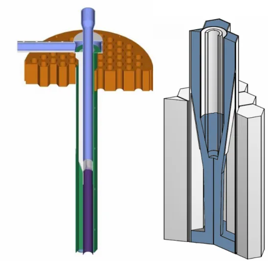
A result of the windowless target option is that at the interaction point, the spallation target is formed by a free liquid surface that must be properly shaped by careful design of the LBE flow. As before, the limited space is responsible for the choice of a vertical confluent flow as formation mechanism for the target free surface (Figure 1). The liquid LBE is fed to the target nozzle via a vertical three-lobed annular pipe to optimise the use of the available space in the core. The target nozzle itself is designed to ensure a stable free surface flow. In addition, monitoring of the free surface
level is mandatory. The design and R&D efforts on this topic will be discussed below. The compact core of the XT-ADS only allows a passage of the LBE target material in one direction from top to bottom. The feeder line passes above the core and the return line underneath it thus interlinking the core. In this configuration, the spallation target loop has an off-axis housing for all active components. A split core base plate is necessary to allow removal of the spallation loop from the main vessel. The off-axis design of the spallation loop leaves the top and bottom of the sub-critical core accessible for fuel manipulations and the installation of irradiation experiments. In addition, the main part of the spallation loop is moved away from the high radiation zone which is beneficial for its lifetime.
Figure 1. Schematic drawing of the vertical confluent flow concept
The common vacuum of the target zone and the proton beam line puts requirements on the vacuum system. Firstly, the pressure directly above the spallation target should be below the 10-5-10-6 Pa range to guarantee compatibility with the vacuum of the proton beam line and to avoid plasma formation caused by the interaction between the rest gas above the target and the proton beam. The pressure condition implies that the outgassing of the spallation target material must be limited and that care should be taken in the design of the vacuum system to ensure sufficient vacuum conductance and pumping capacity. The second essential function of the vacuum system is the confinement of volatile radioactive spallation products. Due to the spallation interaction of the proton beam with the target material, radioactive elements with a high vapour
pressure (e.g. Hg isotopes) are produced. These products could possibly emanate from the free surface of the target and should be confined, either within the spallation loop or in the vacuum system. For this purpose, the latter is equipped with a closed back end composed of sorption and getter pumps. In order to minimise emanation of spallation products into the proton beam line, a large second free LBE surface is foreseen in the servicing vessel, directly underneath the main vacuum pumps.
The spallation target is designed to be capable of handling the heat deposited in the spallation target by a 3 mA, 600 MeV proton beam that amounts to about 1242 kW [4]. Forced convection by circulating liquid target material is used to evacuate the heat trough the spallation target heat exchanger situated at the bottom of the off-axis part of the loop. The secondary side of the heat exchanger is cooled by the main vessel coolant. The flow rate of the LBE is about 10 l/s. The lower limit of this value is determined by the maximum temperature allowed in the target. In order to limit LBE evaporation and corrosion of structural materials in the target loop, this temperature is set at about 430°C. Because the spallation target material is cooled against the main vessel coolant, the lowest achievable temperature during normal operation of 330°C is mainly determined by the inlet temperature of the core (300°C).
The XT-ADS spallation target system has been designed to be compatible with the remote handling scheme envisaged for the entire XT-ADS. The full loop can be removed from the main vessel after unloading of the core. The prior unloading of the core is to avoid criticality issues, for general safety and to allow in situ commissioning of the target unit. In addition, all active elements are placed in a separate sub-unit which allows servicing of these parts without removal of full the spallation loop. The closed outer housing allows regular (yearly) replacement of the spallation target zone that will be required because of radiation induced embrittlement and possible replacement of the heat exchanger. Maintenance, inspection and repair of the spallation unit are foreseen to be performed in the XT-ADS hall, outside the main vessel pool under cover of a protective inert atmosphere. This includes disconnection and reengagement of all service jumpers, replacement of the embrittled loop parts close to the target zone and removal and re-installation of the interior column with all active parts. Also the replacement of the heat exchanger fits into the scheme. Before and after maintenance, the LBE loop is drained and later refilled into and from a special container. This allows save storage of the LBE during maintenance and simultaneously permits conditioning of the material in a dedicated off-line system.
3.2. Spallation loop layout & operation
Figure 2 shows the sub-unit and outside housing of the spallation loop. In Figure 3,
a cut of the interior of the spallation loop together with a schematic layout is shown. All components are indicated and their layout reflects the design status as described in the Draft-2 file. The target LBE is fed from the off-centre spallation unit and traverses to the central axis of sub-critical core. It comes down through the three feeders (forming what is called the downcomer) surrounding the beam transport line. The target free surface is formed at the confluence point of the target nozzle in the centre of the sub-critical core. Here the proton beam impinges from the top. The LBE subsequently flows away from the beam impact zone through the central tube, the lower U-bend and the heat exchanger to the pumping unit in the spallation housing.
For proper operation of the liquid target, the formation of the target free surface and a firm control over the size of the recirculation zone that is formed in the centre of the target free surface is essential. When the recirculation zone is too small, LBE droplets are ejected from the LBE confluent zone that may cause metal evaporation when hit by the beam. If the recirculation zone is too large, it will be directly heated by the proton beam causing the temperatures to increase very rapidly which would also lead to excessive evaporation of LBE and other volatiles.
The size of the recirculation zone can be determined indirectly by its height. In the Draft-2 design, the target free surface height is given by the balance between the nozzle in- and outflow. The height of the recirculation zone is measured by a laser based level measurement device (LIDAR) positioned in line with the beam. This level measurement is used to control the pumping power of the magneto-hydrodynamic (MHD) pump in order to keep the height of the recirculation zone at a fixed level.
The free surface level is particularly difficult to maintain under the dynamics changes caused by beam trips and during the start-up / shut-down procedures. In order to cope with these dynamics, a second free surface in the spallation loop main unit is maintained at about 2.5 m above the target free surface. The mechanical pump lifts the LBE that has passed the heat exchanger to the level of the second free surface. From here, the LBE flows through the feeder-line to the target nozzle by gravity. The MHD pump in the feeder-line provides the fine-tuning of the gravity-fed inflow in 2-quadrant acceleration/deceleration operation. Normal operation of the pump, however, is slightly biased towards an accelerating action to avoid frequent reversal of the travelling wave. The three feeders are drag limited, exceeding the minimum drag of 1 bar/m necessary to compensate for the hydrostatic pressure, to prevent the spallation LBE to tear off and reach the target nozzle in free fall.
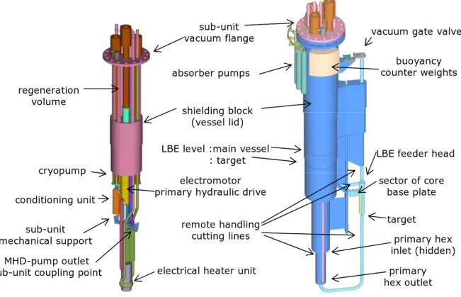
Figure 2. Spallation sub-unit and outside housing of the spallation loop (Draft-2)
sub-unit vacuum flange
shielding block (vessel lid)
vacuum gate valve buoyancy counter weights cryopump conditioning unit regeneration volume sub-unit mechanical support MHD-pump outlet sub-unit coupling point
electromotor primary hydraulic drive
electrical heater unit
target sector of core base plate primary hex outlet absorber pumps
LBE feeder head
remote handling
cutting lines primary hex
inlet (hidden) LBE level :main vessel
In the Draft-2 design, the target nozzle was designed to have a straight LBE flow without detachment of the LBE from the nozzle walls. However, real size water and LBE flow experiments performed respectively at the Université Catholique de Louvain (UCL) [5] and at the KALLA laboratory of the Forschungszentrum Karsruhe (FZK) have shown that a more stable flow is achieved if some detachment of the LBE flow is allowed. Therefore, it is envisaged to incorporate detachment by design in the current version of the target. As is shown in Figure 1, a third free surface is introduced and a free-falling jet is formed at the nozzle outlet. In this way, the nozzle inflow is fully decoupled from the nozzle outflow. The target free surface height is now determined only by the nozzle geometry and the flow rate.
The third free surface acts as a buffer for accommodating transients and eliminates the necessity of active control of in- and outflow by feedback loop consisting of the LIDAR, MHD and mechanical pump. This has serious implications on the layout and function of different components in the loop:
The LIDAR now only fulfils a safety function and its requirements are largely relaxed.
The MHD pump in the inflow section which was needed for fast flow regulation loses this function and only acts as a long term regulator. In principle, it could be eliminated completely leaving only the main pump. In this case, the inflow flow rate is fully determined by the height difference between the second free surface and the target nozzle and the drag in the inlet section. Since it is however possible that the latter changes during the lifetime of the target loop, it is envisaged to keep a flow regulating device in the inflow section.
Different configurations are possible for the main pumping system: its function can be fulfilled by one large mechanical pump in the outflow section or e.g. can be shared between two smaller mechanical or MHD pumps, one in the inflow and one in the outflow section. In the latter case, the height of the second free surface can be reduced and the pressure specifications of the pumps are less demanding.
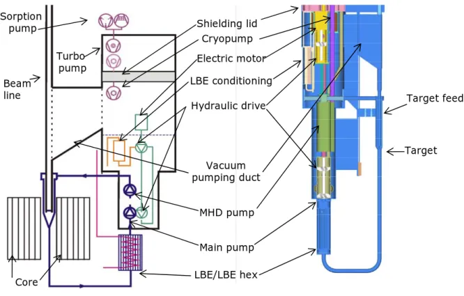
Figure 3. Schematic layout of the spallation loop and its interiors (Draft-2)
A consequence of the interlinking of the spallation target loop with the reactor core is that a change in core dimensions implies a possible change in the length of the downcomer and the position and length of the horizontal feeder and return line. In this respect, it is important to notice that the length of the fuel pins has been increased by 200 mm as compared to Draft-2. In addition, an increased diameter of the sub-critical core must be taken into account.
LBE/LBE hex Cryopump Shielding lid Electric motor LBE conditioning Hydraulic drive MHD pump Main pump Target Vacuum pumping duct Turbo pump Sorption pump Target feed Core Beam line
3.3. Spallation target components
3.3.1. Spallation target nozzle
Within the XT-ADS spallation target design work of the EUROTRANS project, a specific effort is put on the development of the target nozzle. As stated above, in the MYRRHA Draft 2 design file that serves as the input for the XT-ADS, the target nozzle was designed to have a straight LBE flow, without detachment of the LBE from the nozzle walls. However, experiments at UCL and FZK have shown that a more stable flow is achieved if detachment of the LBE flow is allowed. Also, introducing a mild swirl has a stabilising effect. These results are now used as input for further development of the target nozzle. In this respect, three tracks are investigated.
Firstly, the feasibility of a target nozzle that explicitly forces flow detachment is studied. In order to achieve detachment at the right position and nowhere else, a rig in the nozzle wall is created. In addition, the nozzle shape and the in- and outflow cross-sections must be optimised. For this purpose, several nozzle proposals are looked into with CFD calculations , followed by experimental tests using water and LBE flow experiments at UCL and FZK respectively (see Figure 4).
Figure 4. Illustration of different design options for target nozzle shapes with flow detachment in a coaxial and 3-feeder configuration
A similar strategy is being followed for the investigation of the influence of swirl on the target flow. Here, numerical and experimental results show that in the current geometry, the application of a mild swirl of 5%, corresponding to a 1/20 ratio of the tangential relative to the axial LBE velocities, has a small but stabilizing effect on the target free surface. Application of a swirl strength of 10% or higher leads to undesirable free surface behaviour, ultimately leading to an unacceptable strong vortex in the central tube.
The third modification in the target nozzle that is being studied in more detail is the 3-feeder option for the LBE downcomer which has the advantage that optimal use is made of the available space in the ADS core (see Figure 4). Next to the three main design modifications, design activities are performed addressing the flow distribution into the downcomer and drag enhancement in the downcomer itself. The strategy of the project is to investigate the three design modifications separately before they are integrated in one nozzle. The combined nozzle will be further studied using the water flow experiments and fine-tuned in LBE flow experiments at KALLA.
3.3.2. LBE pumping system
In the Draft-2 design the mechanical pump is powered by an indirect hydraulic drive that avoids the use of a long shaft. A canned electric motor drives a pump that transmits its power to the hydraulic drive / hydraulic pump in the lower part of the column. The hydraulic transmission fluid is taken to be the same as the LBE that it is circulating in the spallation loop (although at higher pressure).
One option for the design of the pump-drive tandem is based on common impeller technology. The impeller direction of drive and pump are opposite in order to ease the axial bearing requirements. This design is shown in all pictures of the spallation loop. Another option is to design the pump/drive tandem based on a screw spindle technology. In this option the fluid smoothly follows the spindle motion without being subject to the accelerating or decelerating phases of impeller pumps. Such a smooth flow is assumed to be less bothered by corrosion and cavitation problems. Although the hydraulic drive pump is the reference design in Draft-2, the long shaft option has not been ruled out. Here however, the proper design and testing of the shaft bearings is the most crucial point. The basic concept for the annular linear induction pump or MHD pump is similar to the one used for the MEGAPIE Project at PSI (CH). The MEGAPIE pump is constructed at IPUL (University of Latvia). The MHD pump envisaged in Draft-2 differs from this pump in certain respects in order to obtain the pressure gain of 1.2 bars as required by the spallation loop dynamics. The pump efficiency is almost doubled by better matching the LBE velocity to the mean magnetic field velocity thus decreasing the slip ratio. Furthermore, the pump length is increased to 1.2 m, including an integrated annular magnetic flow meter and the number of poles is increased accordingly. Taking into account the MEGAPIE model findings, the efficiency could be increased even more by grading the magnetic core flux over its length.
In the present design with flow detachment, the MHD pump for fast flow regulation in Draft-2 is obsolete. As described above, different configurations are now possible for the main pumping system consisting of one or two mechanical or MHD pumps. The decision on which configuration to use has not yet been taken.
3.3.3. Heat exchanger
In the heat exchanger (HEX), the LBE from the spallation loop exchanges heat with the LBE from the primary system. The basic option for this component is a counter-current shell and tube heat exchanger with the LBE spallation loop passing through the tubes. The LBE from the primary system is taken from the lower plenum in the reactor vessel and is released above the vessel diaphragm. In this way, it is driven through the HEX by the pressure difference between the lower and upper core plenum (i.e. the pressure drop across the sub-critical core). The HEX is designed in such a way as to minimise pressure losses at the spallation side in order to keep sufficient suction head for the pump downstream.
3.3.4. LIDAR
In the Draft-2 configuration with an active control of the target height using a feedback loop with the LIDAR and MHD pump, LIDAR update rates of several kHz and accuracies in the mm order were necessary. Such systems are not available on the market today and require significant R&D effort.
In the new flow configuration, the LIDAR system has not completely disappeared but the timing and accuracy requirements have changed by several orders of magnitude and have come into reach of commercially available devices. Update rates of 2 Hz and accuracies of 10 cm (with a resolution of 1 cm) are now relevant [6].
3.3.5. Vacuum system
The absence of the window implies that the target needs to be under vacuum to accommodate the vacuum of the accelerator. Thus, a vacuum system must be provided that maintains sufficiently low pressures to avoid plasma formation. In addition, it must ensure sufficient confinement of volatile radioactive spallation products that may emanate from the target. In the Draft-2 design, the spallation unit is connected to the central beam line via a duct and is being pumped as an integrated vacuum system to a pressure of less than 10-5 Pa.. At the back-end of the system, all radioactive volatile emanations are collected in absorption pumps from where they can be batch-wise removed. Because of the target vacuum, the LBE flow is optimised to keep the temperature of the free surface low in order to prevent excessive LBE evaporation into the beam line.
During target nozzle experiments it was observed that the fast flowing LBE in the spallation target zone has a significant vacuum pumping effect since the pressure in the target module was reduced to two orders of magnitude below the minimum pressure reachable by the vacuum pump installed at that time. Although the effect has not been duly quantified in the present target geometry, it does open possibilities for a modification of the vacuum system design. Indeed, the vacuum pumping effect of the LBE may be sufficient to reduce the vacuum pressure in the target zone during normal operation to below the level required. In that scenario, the confinement of the spallation products can be improved by abandoning the vacuum duct between the beam line tube and the servicing vessel. In this way, the vacuum chamber above the free surface in the main vessel has no contact with the beam line and thus migration of volatile radioactive spallation products that were emanated from this free surface to the beam line is prevented. Separation also allows to operate the vacuum vessel at higher pressures of the order of 1-100 Pa which would simplify the vacuum system without changing the
LBE flow behaviour significantly. In addition, the higher operating pressure allows to envisage a room temperature vapour trap in the vessel that would immobilise the bulk of the volatile spallation products, so that the load on the absorption pumps is reduced.
3.3.6. LBE conditioning
Conditioning of the LBE eutectic in the spallation loop is required for two main reasons: corrosion inhibition and the need to prevent conglomeration of insoluble impurities that may lead to a blocking of the flow. In the design of the MYRRHA ADS, the main corrosion inhibition strategy followed is by controlling the oxygen content in the LBE target material to the level of 1.10-6 wght%. For this, a hydrogen and water vapour gas treatment system is foreseen to reduce the amount of oxygen in the LBE when required. However, since the spallation unit is a vacuum system the treatment is only possible during maintenance times. Because of the generally reducing nature of the spallation products and the hydrogen from the proton beam, the opposite reaction for adding oxygen is also included. For this purpose a dedicated conditioning unit is foreseen. Its active component is a heated basket with PbO pebbles housed in an insulated vessel. The exchange rate between the pebbles and the bypass LBE flow is governed by controlling the temperature of the basket. In addition, magnetic filtering is foreseen at the entrance of the MHD pump to extract magnetic corrosion products (mainly Fe and Ni compounds) that could otherwise block the MHD pump. Finally, at the top of the second free surface filtering/skimming is envisaged to remove floating debris.
Summary
The design of the XT-ADS spallation target is performed within the European integrated project EUROTRANS that has started in April 2005. At the current status of the spallation target design process, the boundary conditions for the spallation target loop with respect to the XT-ADS performance requirements and the design of the sub-critical core and primary system have been established. The next steps will concentrate on further development of the spallation target nozzle, the vacuum and spallation product confinement system and the pumping, LIDAR and cooling system.
References
[1] J. Knebel et al., "Integrated project EUROpean research programme for the TRANSmutation of high level nuclear waste in an accelerator driven system, EUROTRANS", EC project No. FI6W-CT-2004-516520, 2005.
[2] G. Van den Eynde et al., "Neutronic design of the XT-ADS core with in-pile-sections", Proc. Conf. HPPA5, Mol, Belgium, 2007.
[3] H. Aït Abderrahim et al., "MYRRHA Pre-Design File - Draft-2", SCK•CEN Report R-4234, Mol, Belgium, 2005.
[4] E. Malambu, Th. Aoust, "Compared design parameters of a 50 MWth MYRRHA core: 350 MeV versus 600 MeV proton beam", SCK•CEN Report, RF&M/EM/em.34.B043200/85/MYRRHA-Design/05-39, Mol, Belgium, 2005.
[5] J.-M. Seynhaeve, "MYRRHA project, Phase 4, Closed loop visualization experiments on four different configurations of the nozzle DG16.5", UCL Report, Louvain-la-Neuve, Belgium, 2002.
[6] M. Dierckx, J. Heyse, "XT-ADS LIDAR Specifications", SCK•CEN Report R-4561, Mol, Belgium, 2007.