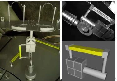
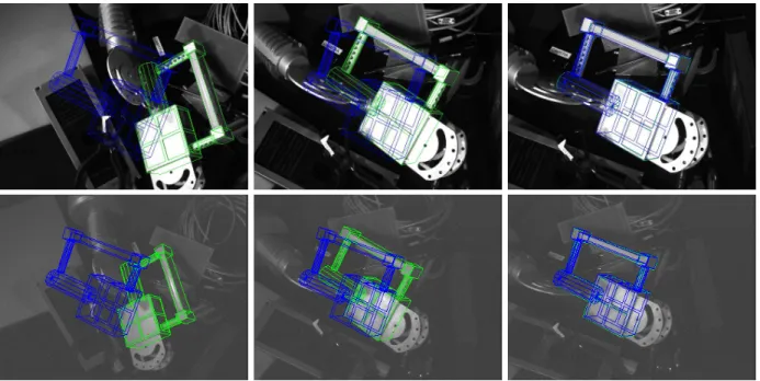
Robust stereo tracking for space applications.
Texte intégral
Figure

Documents relatifs
L’archive ouverte pluridisciplinaire HAL, est destinée au dépôt et à la diffusion de documents scientifiques de niveau recherche, publiés ou non, émanant des
Active vision for pose estimation applied to singularity avoidance in visual servoing.. Don Agravante,
Visual servoing based on the tracking of points of interest: (a) initial image, (b) final image, (c-d) classical visual servoing control law (difference image and point trajectory
Yang, “Real-time part-based visual tracking via adaptive correlation filters,” in Proceedings of the IEEE Conference on Computer Vision and Pattern Recognition, 2015, pp. Hoi,
Despite their differences, all the studies that suggest a structural difference between the two types of DOs are built on the claim that in a neutral or unmarked word
On the right, the ambiguity in the inferred pose of the true camera is shown: its position can lie anywhere on the circle that is centered in the fixed-axis rotation axis,
S’il s’agit de passer de l’orbite ext´ erieure ` a l’orbite int´ erieure, il suffit d’appliquer un d´ ecr´ ement de vitesse ∆v B au point B (i.e. d’utiliser des
Based on previous research discussed above, we hypothesize that (1) piglets would be spontaneously able to find a hidden reward in an object-choice task after the use of visual
