HAL Id: hal-01890815
https://hal-mines-albi.archives-ouvertes.fr/hal-01890815
Submitted on 6 Nov 2018
HAL is a multi-disciplinary open access archive for the deposit and dissemination of sci-entific research documents, whether they are pub-lished or not. The documents may come from teaching and research institutions in France or abroad, or from public or private research centers.
L’archive ouverte pluridisciplinaire HAL, est destinée au dépôt et à la diffusion de documents scientifiques de niveau recherche, publiés ou non, émanant des établissements d’enseignement et de recherche français ou étrangers, des laboratoires publics ou privés.
thermocline storage tank
Muhammad Asaad Keilany, Mathieu Milhé, Jean-Jacques Bézian, Thomas
Fasquelle, Quentin Falcoz, Gilles Flamant
To cite this version:
Muhammad Asaad Keilany, Mathieu Milhé, Jean-Jacques Bézian, Thomas Fasquelle, Quentin Falcoz, et al.. Vitrified asbestos waste used as filler material in a thermocline storage tank. WASTEENG 18 - 7th International Conference on Engineering for Waste and Biomass Valorisation, Jul 2018, Prague, Czech Republic. p.244-253. �hal-01890815�
Page 1 sur 10
VITRIFIED ASBESTOS WASTE USED AS FILLER MATERIAL IN A THERMOCLINE
STORAGE TANK
M. A. KEILANY1,2, M. MILHÉ1, J-J. BÉZIAN1, T. FASQUELLE2, Q. FALCOZ2, G. FLAMANT2
1 Centre RAPSODEE, Universite de Toulouse; Ecole des Mines d’Albi, CNRS, Albi F-81013, France. 2 CNRS-PROMES, 7 Rue du Four Solaire, 66120 Font Romeu-Odeillo, France.
Abstract
Thermocline systems could be an economically viable solution for thermal energy storage (TES) in concentrated solar power (CSP) plants. In this work, the use of Cofalit® as solid filler material inside a thermocline TES in a CSP is studied experimentally with the MicroSol-R pilot-scale facility. Cofalit® is an inert and low cost post-industrial process rocks (recycled material from asbestos wastes), supplied by the French company Inertam [1]. The thermal performance of the thermocline filled with Cofalit® is compared to previous research [2] performed with alumina spheres as filler materials for typical charge and discharge process. Experimentally, it was first observed that the overall porosity of the solid bed increased with Cofalit® with respect to Alumina, due to random shapes and distributed size of the particles. This results in a decrease in volumetric heat capacity from 3.3 MJ/m3K with alumina
spheres to 2.7 MJ/m3K for Cofalit® between 200 and 300 °C. The temperature distribution in the tank
during both charging and discharging phases is also investigated and compared to the reference case. The development of the temperature gradient and its progression exhibit better performance than the reference Alumina case, thus showing a very good thermocline behavior. Thermocline thickness during charge was found 26% of the tank height in Cofalit® case, 7% lower than with Alumina. While charge efficiency was similar for both materials around 79%, Cofalit® has better discharge efficiency (8% better than alumina). The good thermal performance of Cofalit® as filler material is attributed mainly to a greater heat exchange area afforded by its irregular shape. Considering the cost saving of due to the use of Cofalit® and resulted thermal performance of the thermocline, Cofalit® appear as a very good candidate as filler material.
1- INTRODUCTION
Concentrated solar power (CSP) is entitled to supply about 10% of the global electricity demand in 2050 (about 620 GWe) according to IEA [3]. One of the main advantages of CSP is the ability to be integrate a massive and reliable thermal energy storage. The most commercially prevailing technology is the two tanks molten salt sensible heat TES. Andasol 50MWe is considered a typical trough CSP power plant with 7.5 h storage (28,000 ton nitrate molten salts) [4]. Thermocline TES systems could be an economically viable solution for TES in CSP plants because it replaces two-tank TES system with a single tank. Moreover, cheap solid filler materials are used inside the thermocline tank to increase the volumetric heat capacity of the TES and decrease the need for expensive heat transfer fluid (HTF). J.E. Pacheco et al [5] concluded that thermocline filled with cheap filler costs 64% of the two tanks molten salts total cost (36% cost reduction). However, during charge and discharge a thermal gradient layer is developed between hot and cold heat transfer fluid (HTF) which is called the thermocline region or thickness. This region is related to heat diffusion in HTF where the quality of stored energy is degraded inside it, consequently affecting the efficiency of the process, while this layer is expanding during the operation it could account up to 33% of total thermocline TES height [6]. A comparison of the influence of different thermocline design parameters on this thickness, included the thermo-physical properties of filler materials as well as the HTF, tank height and porosity indicated that the tank height and thermo-physical properties of the solid filler are the major parameters affecting the thickness [7].
When selecting a suitable solid filler materials for TES there are certain desired thermo-physical, chemical , mechanical , environmental and commercial properties to be considered [8].Py et al [9] evaluated the use of natural rocks as solid filler materials like granite, gravel and sand in TES. They found that the contaminations in that filler caused significant declination in the oil’s thermos-physical properties (HTF). Beside, upon thermal expansion to the tank wall, fin rocks have a potential to precipitate at the bottom of the tank due to its very small size, preventing the tank’s wall to go back to its original shape when cooled down, and this puts a serious strain on the mechanical integrity of the tank wall.
In this study an experimental evaluation of Cofalit®, a cheap filler material (asbestos containing treated waste) with good thermo-physical properties, is performed, and compared to the reference case of alumina spheres.
2- COFALIT® AS SOLID FILLER OF TES
Source of Cofalit®: Ceramic from asbestos containing waste (ACW)
Asbestos is a general terminology for naturally available fiber-like minerals: it is known for high tensile strength, flexibility, resistance to chemical and thermal degradation, electrical resistance and it can be woven [10]. The main composition of ACW are reported by Gutierrez et al. [11] as follows: O 32 wt%, Ca 31 wt%, Si 23 wt%, Fe–Mg–Al 13 wt%.
Asbestos was widely used during 20th century, it was found in nearly 4000 products[12]. However, in
1995 asbestos was restricted from use in most industrial countries, after confirming its responsibility to fatal pulmonary diseases [13], and all asbestos containing waste (ACW) ordered to special recycling procedures. Out of 250,000 tons per year of ACW produced in France alone, only 6000 tons re-used after treatment road construction[9] while the rest are placed in highly controlled waste land fill. The strict rules for treatment of ACW requires melting based operations at about 1400ºC , that allow complete elimination of the ACW toxicity [11], which implies significant GHG emission and high cost of energy, this increases the need to find ways to reuse these materials and valorize its use.
Cofalit® is a rocklike treated ACW manufactured by INERTAM [1]. It consists mainly of a calcium magnesium iron alumino-silicate with various secondary elements based on the waste source such as Cr, Cu, Zn, Mn, etc..[4]. The French company produces around 3000 tons yearly by subjecting ACW to plasma torch furnace at 1400ºC, then leaving the molten resultant to cool down to ambient temperature without specific operation to control the process [14]. The liquid nature of the primary products allows forming molten Cofalit® in the required shape as molded.
Properties evaluations
Thermo-physical properties:
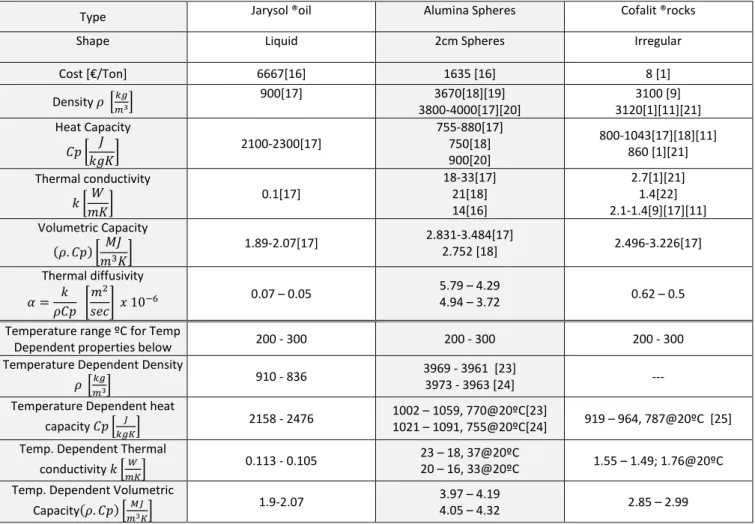
In order to compare the properties of the HTF with the nominated filler materials, Table 1 summarizes most cited values of thermo-physical properties for synthetic oil, Alumina spheres and Cofalit® for quick comparison, along with value obtained from temperature dependent properties in the temperature range (200 – 300) ºC. This will help assessing the reduction of cost and size of the tank taking into account important properties such as volumetric heat capacity, heat conductivity and diffusivity.
Chemical properties:
Chemical stability: Cofalit® had been evaluated as chemically inactive material [15], furthermore, it is thermally stable up to 1200ºC [1].
Page 3 sur 10
Calvet et al [4] examined the compatibility between Cofalit® and two common molten salts, binary salt 60% sodium 40% potassium nitrate, and the ternary salt 42% calcium, 15% sodium, 40% potassium nitrate.
Table 1 summarized Thermo-physical properties from literatures and temperature dependent formulas Type Jarysol ®oil Alumina Spheres Cofalit ®rocks
Shape Liquid 2cm Spheres Irregular
Cost [€/Ton] 6667[16] 1635 [16] 8 [1] Density 𝜌 [𝑘𝑔 𝑚3] 900[17] 3670[18][19] 3800-4000[17][20] 3100 [9] 3120[1][11][21] Heat Capacity 𝐶𝑝 [ 𝐽 𝑘𝑔𝐾] 2100-2300[17] 755-880[17] 750[18] 900[20] 800-1043[17][18][11] 860 [1][21] Thermal conductivity 𝑘 [𝑊 𝑚𝐾] 0.1[17] 18-33[17] 21[18] 14[16] 2.7[1][21] 1.4[22] 2.1-1.4[9][17][11] Volumetric Capacity (𝜌. 𝐶𝑝) [𝑀𝐽 𝑚3𝐾] 1.89-2.07[17] 2.831-3.484[17] 2.752 [18] 2.496-3.226[17] Thermal diffusivity 𝛼 = 𝑘 𝜌𝐶𝑝 [ 𝑚2 𝑠𝑒𝑐] 𝑥 10 −6 0.07 – 0.05 5.79 – 4.29 4.94 – 3.72 0.62 – 0.5 Temperature range ºC for Temp
Dependent properties below 200 - 300 200 - 300 200 - 300 Temperature Dependent Density
𝜌 [𝑘𝑔
𝑚3]
910 - 836 3969 - 3961 [23]
3973 - 3963 [24] --- Temperature Dependent heat
capacity 𝐶𝑝 [𝑘𝑔𝐾𝐽 ] 2158 - 2476
1002 – 1059, 770@20ºC[23]
1021 – 1091, 755@20ºC[24] 919 – 964, 787@20ºC [25] Temp. Dependent Thermal
conductivity 𝑘 [𝑚𝐾𝑊] 0.113 - 0.105
23 – 18, 37@20ºC
20 – 16, 33@20ºC 1.55 – 1.49; 1.76@20ºC Temp. Dependent Volumetric
Capacity(𝜌. 𝐶𝑝) [𝑀𝐽
𝑚3𝐾]
1.9-2.07 3.97 – 4.19
4.05 – 4.32 2.85 – 2.99
No corrosion after subjecting the ceramic to 500ºC for 500 h was observed, confirming the compatibility between Cofalit® and such a binary salt, while further study is recommended to validate the possibility of use with the ternary salt. Fasquelle et al [18] evaluated the compatibility of Cofalit® with synthetic oil at 300 ºC for 500 h, and found it stable, but further investigation was recommended to check how oil properties are actually influenced by cycling operation along with Cofalit®.
Mechanical properties:
Py et al [9] confirmed slightly lower thermal expansion of Cofalit® compared to known high temperature concrete and ceramic, with (α 8.8 10−6𝐾−1), as well as similar value of Young modulus
of 119 GPa. assessing a significant mechanical stability. Commercial Properties:
Abundant material and very competitive price of Cofalit® was confirmed in different studies, with cost as low as 8 euro/ton for the as-produced material [1],[9].
Environmental properties:
Various studies reported the low impact of Cofalit®, as it has no toxicity on the environment and (no is not subject to lixiviation [1][9][26]. Although Jeanjean et al [27] estimated a carbon footprint of 27.48 gCO2/kg for Cofalit® production, the cost of environmental impact is accounted for asbestos
treatment operation and not for the TES[14].
Based on these properties, Cofalit® is as interesting as known ceramic and rocklike materials for sensible heat, but it has significant advantages of low cost and valorization of waste materials.
3- EXPERIMENTAL SETUP
Comparison between Cofalit and alumina was carried out in the same experimental setup that was used by Fasquelle et al [2]. MicroSol-R is a pilot scale CSP plant consisting of 3 parabolic troughs (12m long, 5.76m aperture, focal length 1.7m 7cm receiver diameter each), with total nominal power 150kW(th). The main TES is a 4m³ thermocline tank with a capacity of 220 kWh, consisting of 4
vertically-arranged baskets, reducing the possibility of thermal ratcheting and allowing easy access to change the filler materials.
Thermocouples measuring HTF temperature are distributed in the axial and radial position as illustrated in
Figure 1.
The solid bed height is 2.64 m, and two buffer zones allow a good HTF distribution. In addition to the parabolic troughs, a 70 kW electrical heater is used to charge the thermocline. Two pumps manage HTF flow;, for charge and discharge process. In order to apply similar experimental conditions on different materials and to eliminate the intermittent nature of the solar power, a typical charge/discharge was selected.
Figure 1 Thermocline tank size and thermocouple positions [2] A typical charge/discharge consists in applying similar constant mass flow rate was applied at similar temperature range.
4- RESULTS AND DISCUSSION
Thermocline dynamic behavior was first compared based on non-dimensional temperature profile evolution during charge and discharge for both filler materials. , Additional performance parameters where evaluated to get more insight: thermocline thickness and storage efficiency.
Temperature profile
Taking into account that (Thigh) is the highest temperature during a process, and (Tlow) is the lowest
temperature during the same process. Non-dimensional HTF temperature is defined in Equation 1, non-dimensional axial coordinate is defined in Equation 2:
θ = Tz,t− Tlow Thigh− Tlow Equation 1 z∗= z Htank Equation 2 Temperature profile during charge
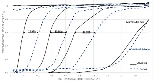
Figure 2 shows the non-dimensional temperature profile inside the thermocline during charge from 248 ºC up to 280 ºC at mass flow rate of 2600 [kg/h] ; where dashed lines represent Cofalit® and solid lines represent alumina.
Both materials start at constant temperature (horizontal profile), and the high temperature oil flowing downward results in the propagation of a steep temperature profile top-down (from the
Page 5 sur 10
right to the left of the figure). If the behavior is similar for both materials, Cofalit TES is fully charged (horizontal profile at 𝜃 ≈ 1) faster than alumina. This behavior can be explained by the higher volumetric heat capacity of alumina compared to Cofalit®, hence alumina needs more time to be charged. In this experimental setup, there is no limitation on the HTF temperature flowing out of the tank.
Figure 2 Alumina – Cofalit® non-dimensional temperature profile during charge, mass flow rate 2600 [kg/h] ΔT 32ºC (280 – 248)ºC However, in a real case a threshold temperature should be taken into account: it is defined as the highest temperatures that can be sent back to the solar field during charge process, referred as Tthr,c,k𝑐
in Equation 3. This threshold temperature limits the charge state of the TES in real operation. Tthr,c,k𝑐 = Tlow+ kc(Thigh− Tlow)
Equation 3 kc is an arbitrary charge factor related to the operational aspects of the solar field , 20% was considered in many previous studies [28].
Figure 3 Alumina – Cofalit® non-dimensional outlet temperature evolution during the charge time, mass flow rate 2600 [kg/h] ΔT 32ºC (280 – 248) ºC
By plotting the non-dimensional outlet temperature over time, (Tthr,c,20%→ θthr,c,20% = 20%), it is
observed from Figure 3, that Cofalit® needed around 78 min to reach its maximum charge, while alumina needed 96 min.
Temperature profile during discharge
Figure 4 reflects the results during discharge from 290 ºC to 218 ºC at mass flow rate of 2950 [kg/h]. It start from fully charged thermocline at the (θ1 horizontally). The discharge cycle finishes it duration when non-dimensional temperature reaches( θ = 0.8) at the non-dimensional spatial coordinates (z*=1), alumina discharged for 12 min more than Cofalit®, this can be attributed to its higher volumetric heat capacity compared to Cofalit®.
Figure 4 Alumina – Cofalit® non-dimensional temperature profile during discharge, mass flow rate 2950 [kg/h] ΔT 72ºC (290 – 218)ºC
Thermocline thickness
During the discharge process, the operation should stop when the outlet temperature reaches the discharge threshold temperature, which is lowest temperature that downstream thermal process can utilize, referred usually as discharge threshold temperature (Tthr,d,k𝑑) that calculated from Erreur !
Source du renvoi introuvable.
Tthr,d,k𝑑 = TH𝑖𝑔ℎ− kd(Thigh− Tlow)
Equation 4 kd: is arbitrary discharge factor related to the operation of the downstream process, most of previous
studies consider the value 20% [28], therefore discharge threshold temperatures is represented as (Tthr,d,20%). Thus, the non-dimensional discharge threshold temperature equals(Tthr,d,20% →
θthr,c,20% = 80%).
Thermocline thickness Equation 5 is the height of the zone contained between two threshold temperatures during charge and discharge [28]: it is actually the part of the storage that cannot be used during operation of the TES in a plant.
𝐻𝑇ℎ𝑖𝑐𝑘(𝑚) = ℎ(Tthr,d,20%) − ℎ(Tthr,c,20%)
Equation 5 Thermocline thickness during charge
Figure 5 illustrates the thermocline thickness during charge for both materials. Thermocline thickness tend to increase sharply at the beginning of charge process until it reaches it maximum value, then it remains at that high value for a until it start to decrease slowly until it has completely vanished when thermocline is fully charged.
It should be noted that in real operation scenario charge must be stopped prior to fully charged status, in order to avoid sending hot HTF back to the solar field. This limitation is set at a certain temperature explained earlier (charge threshold temperature) θthr,c,20% = 20%. So, thickness must be evaluated for a targeted non-dimensional threshold temperature, the thickness with Cofalit® was found 25.5%
Page 7 sur 10
compared to 33% in alumina. This could be attributed to the higher thermal diffusivity which found to lead to bigger thermocline thickness [29], where alumina has value around 5. 10−6 [m²/sec] while Cofalit® has 0,55. 10−6 [m²/sec] Table 1.
Figure 5 Alumina – Cofalit® normalized charge thermocline thickness against non-dimensional outlet temperature during charge, mass flow rate 2600 [kg/h] ΔT 32ºC (280 – 248)ºC
Thermocline thickness during discharge
Figure 6 plots the evolution of the thermocline thickness versus time. When the system reaches its 80% threshold temperature, thermocline thickness with alumina expands up to 23%, while with Cofalit® it increases up to 20% and stabilize until the end of the process. Alumina still has bigger thickness than Cofalit®, which is attributed to higher diffusivity in similar approach to the thickness during charge. On the other hand, both materials didn’t reach their maximum thickness value, that they have during charge process, this could be explained by the faster discharge compared to discharge, which does not allow the thickness to evolve fast enough.
Figure 6 Alumina – Cofalit® Thermocline Thickness evolution during time for discharge at mass flow rate 2950 [kg/h] ΔT 72ºC (290-218) ºC
Charge Efficiency
The efficiency of charge process Equation 6 [16] is identified by the ratio between the accumulated stored energy and the total energy that can be stored in the tank.
𝜂𝑐ℎ𝑎𝑟𝑔𝑒= 𝐸𝑎𝑐𝑐 𝐸𝑚𝑎𝑥 = ∫ (𝐴𝑇𝑎𝑛𝑘 𝑖𝑛𝑡(𝜌. 𝐶𝑝)𝑒𝑓𝑓+ 𝐴𝑤𝑎𝑙𝑙 𝑐𝑟𝑜𝑠𝑠 𝑠𝑒𝑐𝑡𝑖𝑜𝑛(𝜌. 𝐶𝑝)𝑤𝑎𝑙𝑙) . (𝑇𝑧,𝑡(𝐾𝑐)− 𝑇𝑙𝑜𝑤)𝑑𝑧 𝐻 0 [V𝑡𝑎𝑛𝑘(𝜌. 𝐶𝑝)𝑒𝑓𝑓+ 𝑉𝑤(𝜌. 𝐶𝑝)𝑤𝑎𝑙𝑙](𝑇ℎ𝑖𝑔ℎ− 𝑇𝑙𝑜𝑤) Equation 6 Where: (𝜌. 𝐶𝑝)𝑒𝑓𝑓 = 𝜀(𝜌. 𝐶𝑝)𝑓+ (1 − 𝜀)(𝜌. 𝐶𝑝)𝑝. 250
Due the significant contribution of the steel in the stored energy in this pilot storage capacity, the volumetric heat capacity of the wall and the basket was taken into account. Figure 7 illustrates the charge efficiency plotted against non-dimensional outlet temperature. Both materials show very similar efficiency behavior during charge Although, in theory it is possible 100% efficiency based on above definition, in real case charge scenario the charge should stop atTthr,c,20%.
Figure 7 Alumina – Cofalit® charge efficiency versus non-dimensional charge outlet temperature , mass flow rate 2600 [kg/h] ΔT 32ºC (280 – 248)ºC
Thus, the charge process should end and the efficiency of charge has to be considered at that non-dimensional value of outlet temperature 20%.
Hence, charge efficiency in Alumina found a bit lower than Cofalit® by 2%; but this difference cannot be considered as significant with respect to experimental uncertainty, and both material has around 80% charge efficiency.
Discharge Efficiency
During discharge process, the efficiency can be calculated from Equation 7 as the ratio of discharged energy to the initial maximum energy stored in the system (HTF, solid filler and tank walls).
𝜂𝐷𝑖𝑠𝑐ℎ𝑎𝑟𝑔𝑒 =𝐸𝑑𝑖𝑠𝑐ℎ𝑎𝑟𝑔𝑒 𝐸𝑖𝑛𝑖𝑡𝑖𝑎𝑙 =
∫0𝑡(𝐾𝑑)𝑚𝑓𝐶𝑝𝑓. (𝑇𝑜𝑢𝑡− 𝑇𝑖𝑛)𝑑𝑡
[(𝑉𝑓+ 𝑉𝑝)(𝜌. 𝐶𝑝)𝑒𝑓𝑓+ 𝑉𝑤(𝜌. 𝐶𝑝)𝑤𝑎𝑙𝑙](𝑇ℎ𝑖𝑔ℎ− 𝑇𝑙𝑜𝑤)
Equation 7 Therefore, by plotting the efficiency of the discharge against the non-dimensional outlet temperature, discharge has to stop when the out let temperature reaches the threshold discharge temperatureFigure 8, it can be noted that Cofalit® has a better discharge efficiency than alumina, 80% and 70% respectively.
Then overall efficiency of alumina can be obtained by multiplying charge by discharge efficiency, which is about 56% compared to 64% for Cofalit®.
The discharge experiment started from completely charged thermocline which is not possible during real case scenario, so taking into account a larger thermocline thickness in alumina this is expected to lower the efficiency for discharge with respect to the calculated one, which will weigh more for Cofalit® overall efficiency.
Although, thermal conductivity in Cofalit® is lower than alumina, it was found that Cofalit® is performing better because of its lower diffusivity, which governs the thermocline thickness mainly, according to Mira-Hernández et.al [29]: higher diffusivity leads to wider thermocline thickness. Moreover, Cofalit® irregular shape and distributed particle sizes result in greater surface area for heat exchange and thus a more efficient charge or discharge process.
Page 9 sur 10
Figure 8 Alumina – Cofalit® Discharge efficiency evolution in time for mass flow rate 2950 [kg/h] ΔT 72ºC (290-218) ºC
5- CONCLUSIONS
Two materials were experimentally evaluated as solid filler in thermocline thermal energy storage for concentrated solar power plant. The performance of asbestos contained waste material Cofalit® compared to alumina as reference ceramic material with spherical shape. Although Cofalit® has lower volumetric heat capacity of 2.7 [MJ/m³.K] compared to 3.3 [MJ/m³.K] for alumina, Cofalit® has fraction of the cost with estimated price of 8 [€/ton] when alumina cost around 6670 [€/ton]. The charge efficiency was very similar for both materials at 80%, thermocline thickness was thinner in Cofalit® than alumina with 26%, 33%, respectively, while it took almost 20% more time to charge alumina than Cofalit due to its bigger volumetric heat capacity.
During discharge, both solid filler have relatively similar thermocline thickness of 20%, unlike discharge efficiency that reached 80% in Cofalit® and 70% in alumina, with overall estimated efficiency 64%, 56%. These results suggest that Cofalit® outperforms alumina ceramic at the temperature level of this work 300 ºC, while small drawback of volumetric heat capacity can be compensated with the competitive cost of supply for Cofalit®.
Thermal energy storage for concentrated power plant provides big opportunity to valorize asbestos treated waste such Cofalit®. It is recommended to test this material for higher temperature range such as 600 ºC- 800ºC to enable wider applications, consequently benefiting both reducing the impact of waste material on the environment, and allow wider penetration for CSP as potential renewable energy.
Acknowledgements
This work was supported by French “Investments for the future” program managed by the National Agency for Research under contract ANR-10-LABX-22-01 (labex SOLSTICE).
6- REFERENCES
[1] X. Py, N. Calvet, R. Olives, P. Echegut, C. Bessada, and F. Jay, “THERMAL STORAGE FOR SOLAR POWER PLANTS
BASED ON LOW COST RECYCLED MATERIAL,” vol. 3, no. 1.
[2] T. Fasquelle, Q. Falcoz, P. Neveu, F. Lecat, N. Boullet, and G. Flamant, “Operating results of a thermocline thermal energy storage included in a parabolic trough mini power plant,” AIP Conf. Proc., vol. 1850, 2017.
[3] IEA, “Technology Roadmap,” SpringerReference, p. 52, 2014.
[4] N. Calvet et al., “Compatibility of a post-industrial ceramic with nitrate molten salts for use as filler material in a thermocline storage system,” Appl. Energy, vol. 109, pp. 387–393, 2013.
[5] J. E. Pacheco, S. K. Showalter, and W. J. Kolb, “Development of a Molten-Salt Thermocline Thermal Storage System for Parabolic Trough Plants,” J. Sol. Energy Eng., vol. 124, no. 2, pp. 153–159, 2002.
[6] C. Xu, Z. Wang, Y. He, X. Li, and F. Bai, “Sensitivity analysis of the numerical study on the thermal performance of a packed-bed molten salt thermocline thermal storage system,” Appl. Energy, vol. 92, pp. 65–75, 2012.
[7] A. M. Bonanos and E. V. Votyakov, “Sensitivity analysis for thermocline thermal storage tank design,” Renew.
Energy, vol. 99, pp. 764–771, 2016.
[8] S. Khare, M. Dell’Amico, C. Knight, and S. McGarry, “Selection of materials for high temperature sensible energy
storage,” Sol. Energy Mater. Sol. Cells, vol. 115, pp. 114–122, 2013.
[9] X. Py et al., “Recycled Material for Sensible Heat Based Thermal Energy Storage to be Used in Concentrated Solar
Thermal Power Plants,” J. Sol. Energy Eng., vol. 133, no. 3, p. 031008, 2011.
[10] Robert L. Virta, Worldwide Asbestos Supply and Consumption Trends from 1900 through 2003, vol. 34, no. 10.
2006.
[11] A. Gutierrez et al., “Advances in the valorization of waste and by-product materials as thermal energy storage (TES) materials,” Renew. Sustain. Energy Rev., vol. 59, pp. 763–783, 2016.
[12] L. D. Maxim, “Asbestos: Risk Assessment, Epidemiology, and Health Effects,” Int. J. Toxicol., vol. 25, no. 2, pp. 139–141, 2006.
[13] E. Gomez, D. A. Rani, C. R. Cheeseman, D. Deegan, M. Wise, and A. R. Boccaccini, “Thermal plasma technology for
the treatment of wastes: A critical review,” J. Hazard. Mater., vol. 161, no. 2–3, pp. 614–626, 2009.
[14] Y. Lalau, X. Py, A. Meffre, and R. Olives, “Comparative LCA Between Current and Alternative Waste-Based TES for
CSP,” Waste and Biomass Valorization, vol. 7, no. 6, pp. 1509–1519, 2016.
[15] N. Pfleger, T. Bauer, C. Martin, M. Eck, and A. Wörner, “Thermal energy storage – overview and specific insight into nitrate salts for sensible and latent heat storage,” pp. 1487–1497, 2015.
[16] T. Fasquelle, “Délivré par UNIVERSITE DE PERPIGNAN VIA DOMITIA Préparée au sein de l ’ école doctorale
Energie Environnement ED 305 PROMES-CNRS UPR 8521 Spécialité : Sciences de l ’ Ingénieur - Énergétique et Génie des Procédés MODELISATION ET CARACTERISATION EXPERIMENT,” 2017.
[17] R. Tiskatine et al., “Suitability and characteristics of rocks for sensible heat storage in CSP plants,” Sol. Energy
Mater. Sol. Cells, vol. 169, no. May, pp. 245–257, 2017.
[18] T. Fasquelle, Q. Falcoz, P. Neveu, J. Walker, and G. Flamant, “Compatibility Study Between Synthetic Oil and Vitrified Wastes for Direct Thermal Energy Storage,” Waste and Biomass Valorization, vol. 8, no. 3, pp. 621–631, 2017.
[19] J. Felinks et al., “Particle-particle heat transfer coefficient in a binary packed bed of alumina and zirconia-ceria particles,” Appl. Therm. Eng., vol. 101, pp. 101–111, 2016.
[20] T. Esence, A. Bruch, S. Molina, B. Stutz, and J. F. Fourmigué, “A review on experience feedback and numerical modeling of packed-bed thermal energy storage systems,” Sol. Energy, vol. 153, pp. 628–654, 2017.
[21] Z. S. Chang, X. Li, C. Xu, C. Chang, and Z. F. Wang, “The design and numerical study of a 2MWh molten salt thermocline tank,” vol. 69, pp. 779–789, 2015.
[22] F. Motte, S. L. Bugler-Lamb, Q. Falcoz, and X. Py, “Numerical study of a structured thermocline storage tank using vitrified waste as filler material,” Energy Procedia, vol. 49, pp. 935–944, 2013.
[23] P. Auerkari, “Mechanical and physical properties of engineering alumina ceramics,” 1996.
[24] M. MUNRO, “Evaluated Material Properties for a Sintered alpha-Alumina,” J. Am. Ceram. Soc., vol. 80, no. 8, pp.
1919–1928, 2005.
[25] H. Agalit, N. Zari, M. Maalmi, and M. Maaroufi, “Numerical investigations of high temperature packed bed TES
systems used in hybrid solar tower power plants,” Sol. Energy, vol. 122, pp. 603–616, 2015.
[26] a. Meffre, R. Olives, X. Py, C. Bessada, P. Echegut, and U. Michon, “Design and Industrial Elaboration of Thermal Energy Storage Units Made of Recycled Vitrified Industrial Wastes,” Vol. 4 Energy Syst. Anal. Thermodyn. Sustain.
Combust. Sci. Eng. Nanoeng. Energy, Parts A B, pp. 757–762, 2011.
[27] A. Jeanjean, R. Olives, and X. Py, “Selection criteria of thermal mass materials for low-energy building construction applied to conventional and alternative materials,” Energy Build., vol. 63, pp. 36–48, 2013.
[28] T. Fasquelle, Q. Falcoz, P. Neveu, and J. F. Hoffmann, “A temperature threshold evaluation for thermocline
energy storage in concentrated solar power plants,” Appl. Energy, vol. 212, no. January, pp. 1153–1164, 2018.
[29] C. Mira-Hernández, S. M. Flueckiger, and S. V. Garimella, “Numerical Simulation of Single- and Dual-media
Thermocline Tanks for Energy Storage in Concentrating Solar Power Plants,” Energy Procedia, vol. 49, pp. 916– 926, 2014.
![Figure 2 Alumina – Cofalit® non-dimensional temperature profile during charge, mass flow rate 2600 [kg/h] ΔT 32ºC (280 – 248)ºC](https://thumb-eu.123doks.com/thumbv2/123doknet/12441858.335430/6.892.189.696.199.543/figure-alumina-cofalit-dimensional-temperature-profile-during-charge.webp)
![Figure 5 Alumina – Cofalit® normalized charge thermocline thickness against non-dimensional outlet temperature during charge, mass flow rate 2600 [kg/h] ΔT 32ºC (280 – 248)ºC](https://thumb-eu.123doks.com/thumbv2/123doknet/12441858.335430/8.892.187.706.157.379/figure-alumina-cofalit-normalized-thermocline-thickness-dimensional-temperature.webp)
![Figure 7 Alumina – Cofalit® charge efficiency versus non-dimensional charge outlet temperature , mass flow rate 2600 [kg/h] ΔT 32ºC (280 – 248)ºC](https://thumb-eu.123doks.com/thumbv2/123doknet/12441858.335430/9.892.193.710.202.447/figure-alumina-cofalit-charge-efficiency-versus-dimensional-temperature.webp)
![Figure 8 Alumina – Cofalit® Discharge efficiency evolution in time for mass flow rate 2950 [kg/h] ΔT 72ºC (290-218) ºC](https://thumb-eu.123doks.com/thumbv2/123doknet/12441858.335430/10.892.191.701.122.451/figure-alumina-cofalit-discharge-efficiency-evolution-time-mass.webp)
