HAL Id: hal-02267722
https://hal.archives-ouvertes.fr/hal-02267722
Submitted on 19 Aug 2019
HAL is a multi-disciplinary open access
archive for the deposit and dissemination of
sci-entific research documents, whether they are
pub-lished or not. The documents may come from
teaching and research institutions in France or
abroad, or from public or private research centers.
L’archive ouverte pluridisciplinaire HAL, est
destinée au dépôt et à la diffusion de documents
scientifiques de niveau recherche, publiés ou non,
émanant des établissements d’enseignement et de
recherche français ou étrangers, des laboratoires
publics ou privés.
Synoptic: a DSML for On-Board Real-Time Software
Design
Alexandre Cortier, J Bodeveix, M Filali, G. Garcia, E. Morand, Marc Pantel,
A Rugina, Martin Strecker, Jean-Pierre Talpin
To cite this version:
Alexandre Cortier, J Bodeveix, M Filali, G. Garcia, E. Morand, et al.. Synoptic: a DSML for
On-Board Real-Time Software Design. 5th European Congress on Embedded Real Time Software and
Systems (ERTS2 2010), May 2010, Toulouse, France. �hal-02267722�
Synoptic: a DSML for On-Board Real-Time Software Design
A. Cortier
1, J.P. Bodeveix
1, M. Filali
1, G. Garcia
2, E. Morand
3, M. Pantel
1, A. Rugina
4,
M. Strecker
1, J.P. Talpin
51: IRIT-ACADIE, Université Paul Sabatier, 118 Route de Narbonne 31062 Toulouse, France 2: Thales Alenia Space, 100 Boulevard Midi, 06150 Cannes, France
3: CNES – DCT/SB/LV, 18 Avenue Edouard Belin 31401 Toulouse, France 4: EADS Astrium, 31 rue des Cosmonautes Z.I Palays 31402 Toulouse, France
5: IRISA-ESPRESSO, Campus de Beaulieu 35042 Rennes, France
Abstract: The ANR exploratory project SPaCIFY
[19,20] designs and implements a domain-specific environment, for real-time embedded space application and control software. Synoptic is an Eclipse-based modeling environment which aims to support all aspects of aerospace software design. In this context, a Domain Specific Modeling Language (DSML) called Synoptic has been defined in collaboration with the industrial end users of the project. Relying on the standard modeling languages used in the domain such as Simulink/Stateflow and AADL, Synoptic DSML covers the design of application and control modules using synchronous programs, dataflow diagrams, mode automata, and also the partitioning, timing and mapping of these module onto satellite architectures. This paper describes the main features of Synoptic DSML. A case study illustrates the concepts introduced in this paper.
Keywords: IDM, DSML, Embedded Systems,
synchronous semantics
1. Introduction
A satellite is an unmanned spacecraft. The system architecture is usually specialized according to the satellite mission. There are two main subsystems: the payload is an application equipment such as specific scientific instrumentation for instance; the platform consists of mechanical structure, sensors and actuators used by the payload and devices for communication with ground stations. The ANR SPaCIFY exploratory project focuses on the flight software embedded in the satellite to manage its platform, also called on-board software. The flight software is a real-time software that provides services that are common to whatever mission-specific payload the spacecraft is assigned. Typical services include reaching and following the desired attitude and orbit, managing thermal regulation systems, power sources, monitoring system status, managing on-board network (MIL-STD-1553, OBDH, SpaceWire), and communicating with ground stations.
Even after the satellite has been launched, flight software must be adapted. Satellites are subject to high energy particles that may damage hardware
components. Such damages cannot be fixed except by installing software workarounds. Bug fixes and software updates should be propagated to flying satellites. In addition, mission extensions may require functional enhancements.
As flight software is critical to the success of the mission, space industries and agencies have worked on engineering processes in order to help increase reliability. For instance, the European Space Agency has published standards (ECSS-E-40) on software engineering and (ECSS-Q-ST-80) on product assurance. These standards do not prescribe a specific process. They rather formalize documents, list requirements of the process and assign responsibilities to involved partners. Regarding updates, standards stipulate for instance that the type, scope and criticality must be documented; that updates must be validated; and so on. Industries are free to come up with their own conforming processes. The SPaCIFY project aims to define such a process and supporting tools based on Model-Driven Engineering (MDE), synchronous languages and the Globally Asynchronous Locally Synchronous System (GALS) paradigm.
2. Models used
Two main kinds of models are commonly used in order to design the platform software: on the one hand, the description of the platform itself, its hardware and software architecture, CPU, memory, storage, communication buses, sensors, actuators, hardware communication facilities, operating system, tasks, software communication facilities, and on the other hand, the command and control algorithms involved in the management of the platform. All these models have common features. First, the notion of mode is central to represent the various states or configurations of both hardware and software (for example: init, reset, on, low power, failure, safe). The modes and their management are usually expressed using finite automata. Second, the functional blocks, data exchange buses and signals are used to represent both the hardware and software architectures, and the command and control software.
However, the current models only provide a partial account of the constraints that the final system must
satisfy. The designers usually encode these hidden constraints using the available constructs in the modeling languages, even if this was not the initial purpose of the construct used. This is usually the case for hard real-time constraints. The designers will rely on explicit management of the control-flow in dataflow models in order to manage the concurrency between the activities. But, the real timing constraints are not explicitly given in the model, they are handled by the designers who sequence the activities, but there is no real specification of the intended result. Thus it requires a very difficult verification phase that can only occur on the final target. This is the current main difficulty: using model constructs for other purposes than their intended ones without any formal, model-level traceability to the initial constraints.
Currently, industrial main actors are relying on the Matlab toolboxes, Simulink and Stateflow from the MathWorks [1] for expressing the command and control algorithms for the various sub-systems of the platform. These models are built by command and control engineers taking into account several kinds of constraints:
the hardware which is usually known very early (in particular if it handles timing and synchronization constraints related to sensors and actuators, which must be activated and will produce results in very precise timing patterns);
the system mode management that impacts the execution of the various sub-systems;
the specification of the intended sub-system. The Simulink and Stateflow toolboxes allow a very wide range of modeling methods, from continuous partial differential equations to graphical functional specifications. Each industrial actor has a well defined process which defines the restricted subset of the modeling language that will be used at each phase of the development cycle. In the ITEA GeneAuto project [2], a subset of these toolboxes was defined that fits the needs for the modeling of space applications from early design to automated target code generation.
The industrial partners of SPaCIFY took also part in GeneAuto. This subset aimed at providing a solid semantic background that would ease the understanding and the formal verification of models. This subset was chosen as an entry point for the design of the Synoptic language. One key point is the use of control-flow signals and events (called in Simulink function call events) in order to manage explicitly the sequencing of the blocks in dataflow models. This is an important point which is significantly different on the semantics side from the classical dataflow modeling languages such as SCADE [3] or RT-Builder [4] which do not provide a specific modeling construct for this purpose, but
allow to encode it through empty data signals that are added between each block in the intended sequencing path. The key point is that the intended hard real-time constraints are not explicit.
Thus it is mandatory to handle the control-flow construct exactly in its usual semantics not using an approximate encoding which only works most of the time but is not proven to work in all cases. Several studies have been conducted by industrial main actors regarding the modeling of hardware and software architecture. HOOD [5] and CCM [6] have been used for many real projects; AADL [7, 8], SysML [9] and UML/MARTE [10] have been evaluated using already existing projects that could be modeled and the results compared with the real systems. Once again, these languages provide a very wide range of modeling constructs that must be reduced or organized in order to be manageable. In the European ASSERT project [11], two tracks were experimented related to these languages, one mainly synchronous based on the LUSTRE [12] and SIGNAL [13] languages, the other mainly asynchronous based on the RAVENSCAR Ada [14] profile. The industrial partners from SPaCIFY were also part of ASSERT. Thus, the results of these experiments were also used as entry points for the design of the Synoptic language.
In the current software development process, command and control models are formal specifications for the software development. These specifications have been validated by command and control engineers by using model simulators. The hardware architecture is currently defined in a semi-formal manner through structured documents. In the near future, models in AADL, or in a subset of SysML/UML/MARTE similar to AADL, will be used to give a formal specification of the architecture.
Then, software engineers either develop the software and verify its conformance to the specification, or use automated code generators; the software is then split in parts that are mapped to threads from the RTOS. They are then scheduled according to the real-time constraints. The know-how of engineers lies in finding the best splitting, mapping and scheduling in order to minimize the resources used. One of the purposes of introducing Model Driven Engineering is to be able to automate partly these manual transformations and the verification that their result satisfies the specification. The Synoptic language should thus allow importing command and controlling models expressed in Simulink/Stateflow, and hardware architecture models expressed in AADL. The associated toolset should assist in the reorganization of the model, and allow to express the mapping and scheduling.
3. Synoptic : DSML for aerospace systems
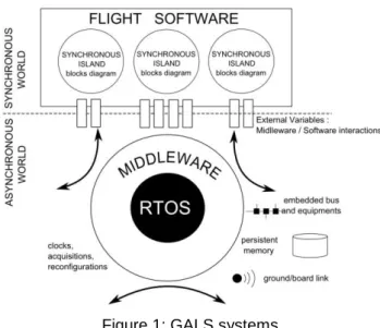
Figure 1: GALS systems.
The satellite management software is usually divided in parts that are quite autonomous one from the other, even if they share the same platform and resources. Inside each of these parts, the subparts are most of the time strongly linked and must cooperate in a synchronous manner. These parts usually exchange information but with less time critical constraints, thus relying on asynchronous exchanges. This kind of system is usually called Globally Asynchronous, Locally Synchronous (GALS).
The SPaCIFY approach involves the design and development of such systems using a GALS architecture dedicated to space. Fig. 1 shows the high level architecture used by the consortium. The flight software consists of a set of subsystems, called synchronous islands, which encapsulates the main functionalities of the system as the Attitude and Orbit Control System (AOCS). These blocks can communicate with each other, with other equipment or with the ground station via the middleware services. The middleware is built on a real-time kernel that provides basic services such as tasks management and synchronization primitives. The middleware provides high level services such as a PUS interpreter (Packet Utilization Standard) [18] responsible for routing telecommands to other services.
The main abstraction service provided by the middleware is the concept of external variables. External variables are used as interfaces between the application tasks of the flight software (i.e. synchronous islands) and the services of the middleware. The external variables are instantiated in the source code as memory cells which are associated with specific treatments. The treatments performed are defined by the configuration of the middleware, in particular through contracts specified in the design. In such an architecture, the
middleware provides a synchronous abstraction of the real-world to the application tasks of the system. He is responsible for ensuring the synchronization of read and write access to external variables in order to guarantee the determinism of synchronous islands.
3.2 Synoptic overview
Synoptic is a Domain Specific Modeling Language (DSML) designed to cover a large part of embedded flight-software design. As such, Synoptic consists of heterogeneous modeling and programming principles defined in collaboration with the industrial partners and end users of the SPaCIFY project. Used as the central modeling language of the SPaCIFY model driven engineering process, Synoptic allows describing different layers of abstraction: at the highest level, the software architecture models the functional decomposition of the flight software. This is mapped to a dynamic architecture which defines the thread structure of the software. It consists of a set of threads, where each thread is characterized by properties such as its frequency, priority and activation pattern (periodic, sporadic).
Figure 2: Synoptic Global view.
At the lowest level, the hardware architecture permits to define devices (processors, sensors, actuators, busses) and their properties. Synoptic permits to describe three types of mappings between these layers (Fig. 2):
mappings which define a correspondence between the software and the dynamic architecture, by specifying which blocks are executed by which threads;
mappings which describe the correspondences between the dynamic and hardware architecture,
by specifying which threads are executed by which processor:
and mappings which describe a correspondence between the software and hardware architecture, by specifying which data is transported by which bus for instance.
Our aim is to synthesize as much of these mappings as possible, for example by appealing to internal or external schedulers. However, to allow for human intervention, it is possible to give a fine-grained mapping, thus overriding or bypassing machine-generated schedules.
Anyway, consistency of the resulting dynamic architecture is verified by the SPaCIFY tool suite, based on the properties of the software and dynamic model. At each step of the development process, it is also useful to model different abstraction levels of the system under design inside a same layer
(functional, dynamic or hardware architecture). Synoptic covers this capability by providing an incremental design framework and refinement features.
To summarize, Synoptic deals with dataflow diagrams, mode automata, blocks, components, dynamic and hardware architecture, mapping and timing. In this section we focus on the functional part of the Synoptic language which permits to model software architecture. This sub-language is well adapted to model synchronous islands and to specify interaction points between these islands and the middleware platform using the concept of external variables. Synchronous islands and middleware form a Globally Asynchronous and Locally Synchronous (GALS) system.
Software architecture. The development of the Synoptic software architecture language has been tightly coordinated with the definition of the GeneAuto language [16]. Synoptic uses essentially two types of modules, called blocks in Synoptic, which can be mutually nested: dataflow diagrams and mode automata. Nesting favors a hierarchical design and allows to view the description at different levels of details. By embedding blocks in the states of state machines, one can elegantly model operational modes: each state represents a mode, and transitions correspond to mode changes. In each mode, the system may be composed of other sub-blocks or have different connection patterns among components.
Apart from structural and behavioral aspects, the Synoptic software architecture language allows to define temporal properties of blocks. For instance, a block can be parameterized with a frequency and a worst case execution time which are taken into account in the mapping onto the dynamic architecture.
3.3 Synchronous formal semantics
Synoptic has a formal semantics, defined in terms of the synchronous language SIGNAL [21]. On the one hand, this allows for neat integration of verification environments for ascertaining properties of the system under development. On the other hand, a formal semantics makes it possible to encode the meta-model in a proof assistant. In this sense, Synoptic will profit from the formal correctness proof and subsequent certification of a code generator that is under way in the GeneAuto project.
Synoptic is equipped with an assertion language that allows to state desired properties of the model under development. We are mainly interested in properties that permit to express, for example, coherence of the modes such as : ‘if component X is in mode m1, then component Y is in mode m2 or can eventually move into mode m2’.
Specific transformations extract these properties and pass them to the verification tools Altarica [16].
3.4 Synoptic architecture models
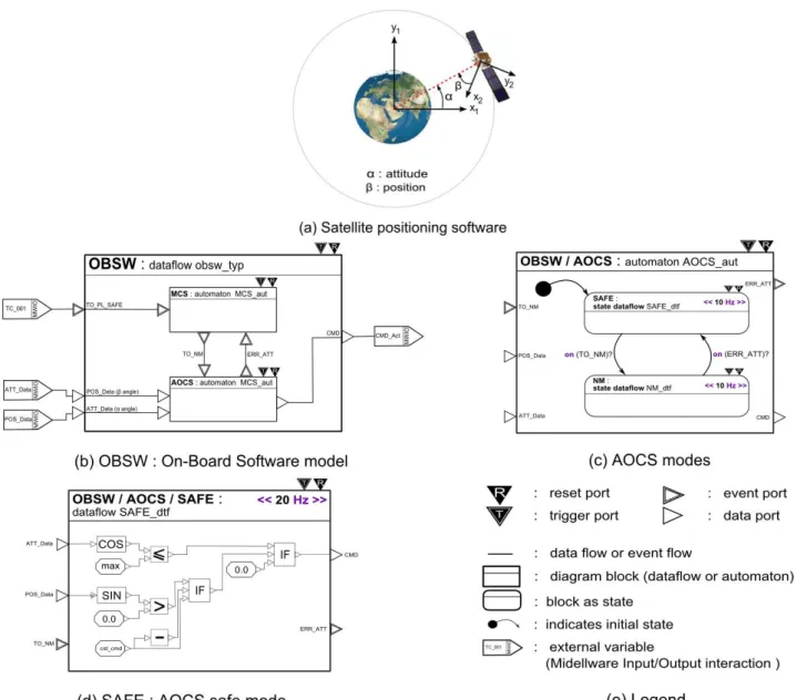
One typical case study under investigation in the project is generic satellite positioning software, Fig. 3 (a). It is responsible for automatically moving the satellite into a correct position before starting interaction with the ground.
Block diagrams. A Synoptic model is a graphical
block-diagram. A Synoptic block-diagram is a hierarchy of nested blocks. As such, you can navigate through different levels of abstraction and
see increasing levels of model details. A block is a functional unit that communicates with other blocks through its interface.
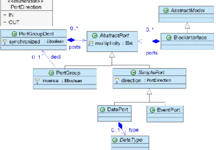
Block Interface. A block interface consists of
communication ports. A port can be either an event port or a data port and is characterized by its direction (in or out). Data ports can be typed using simple data types. However, typing data ports is optional in the early stages of design to give the designer the flexibility to describe abstract models. As shown in Fig.3, which represents a part of the Synoptic meta-model, it is possible to encapsulate a set of ports within a single entity called group of ports (PortGroup in Fig. 4).
Figure 4: Synoptic Meta-model : Interface. A group of ports is used to group a set of ports which are conceptually linked. As specified by the synchronized property of the PortGroupDecl meta-model class, it is possible to specify a synchronization constraint on ports constituting the group. A block interface can be implemented by different types of blocks: dataflows, automata or externals, Fig. 5.
Figure 5: Synoptic Meta-model : Model Diagram.
Dataflows. A dataflow block models a dataflow
diagram. It embodies sub-blocks and specifies data or event flows between them. A flow is a directed connection between ports of sub-blocks. A sub-block
is either an instance of dataflow, automaton or external block, or an instance of block interface (see ModelInstance class in Fig. 4). In the latter case, the model is abstract: the designer must implement all the block interfaces used to type sub-blocks in order to obtain a concrete model. As such, Synoptic environment design promotes a top-down approach.
Automata. An automaton block models state
machines. A Synoptic automaton consists of states and transitions. As for dataflow, a state can be represented by an instance of dataflow, automaton or block interface. Dataflow diagrams and automata can be hierarchically nested; this allows for a compact modeling of operational modes.
Apart from the ongoing actions of automata (block embedded in state), it is possible to specify entry and exit actions in an imperative style. Transitions between states are guarded and equipped with actions. There are two types of transitions in Synoptic: strong and weak transitions.
Strong transitions are used to compute the current state of the automaton (before entering the state), whereas weak transitions are used to compute the state for the next instant. More precisely, the guards of weak transitions are evaluated to estimate the state for the next instant, and the guards of strong transitions whose source is the state estimated at the previous instant, are evaluated to determine the current state.
Externals. A common practice in software industry
is the re-use of external source code: designers must be able to introduce blocks representing existing source code into the model. Moreover, for modeling flight software functional units, it is necessary to use primitive operations such as addition, cosine, division... Synoptic provides the concept of external block to model primitive blocks and external source code. Primitive blocks are encapsulated in a Synoptic library. The Synoptic tool suit recognizes these primitive operations during code generation. For embedding an external source code, the procedure is quite different. The designer must build his own external block by defining its interface, by giving the source code path which will be used at code generation time, and by specifying pre/post conditions and the Worst Case Execution Time of the functional unit.
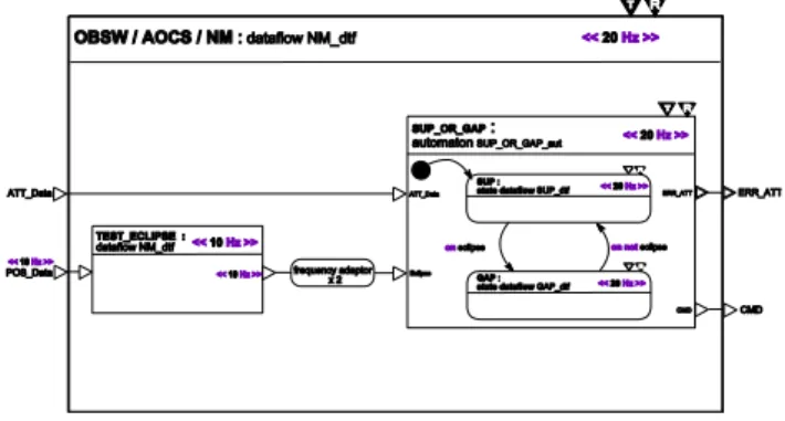
Example. Fig.6 shows the graphical decomposition
of the nominal mode of the Attitude and Orbit Control System (AOCS/NM) depicted in (Fig. 3 (c)). The header of the block tells us that NM is an instance of the NM_dtf dataflow block. In nominal mode, AOCS can either use its sun pointing sensors (SUP) to define its position or, during eclipse, use its geocentric pointing sensors (GAP). To model this
activity, the nominal mode of the AOCS flight software encapsulates two sub-blocks: one dataflow block (TEST_ECLIPSE) which detects an eclipse occurrence and one automaton block (SUP_OR_GAP) which ensures the change of sub-mode (SUP or GAP) depending on the outcome of the eclipse test block.
Figure 6: AOCS nominal sub-mode.
3.5 Modelling synchronous islands of GALS systems A functional model consists of synchronous islands. A synchronous island is a synchronous functional unit in interaction with the middleware. The middleware supports the execution of code generated from the Synoptic model: it provides a synchronous abstraction of the asynchronous real world. To ensure proper integration of the generated code with the middleware platform, it is essential to locate all interactions between the middleware and the application. Our approach is to locate all these interactions into a single concept in Synoptic: the concept of external variables.
External variables allow to represent in Synoptic models the following domain specific and technical concepts: telecommand, telemetry, constants database systems, shared variables and persistent variables (on reboot). The specification of external variables is used for code generation and middleware configuration. Therefore a Synoptic synchronous island is a block in which all input and output signals are connected to external variables. The OBSW block of our case study is one such synchronous island, Fig. 3 (b).
Contractual approach. An external variable is a
variable managed by the middleware. It can be read or written by multiple clients (components of the application). Contracts are used to specify how to control this access. The configuration of an external variable is done using four levels of contracts:
a classical syntactic contract that includes its name and type ;
a persistence contract that specifies if the variable is persistent on reboot or not ;
a synchronization contract that describes the possible concurrent interactions when the variable is shared.
Each component using such a variable must also provide a usage contract that defines the protocol it will use to access the variable. These contracts allow the middleware to manage these variables. Thus, the synchronization contract will indicate if locks are needed and when they should be used. The persistence contract will indicate how the variable should be stored (RAM or permanent memory). The monitoring functions of the variable that the middleware must implement are defined by the remote access contract and the usage contracts.
3.6 Control and temporal properties
As described before, blocks are functional units of compilation and execution. Block execution is controlled using two specific control ports: trigger and reset ports. These ports are inherited from the Simulink/Stateflow approach. These ports appear as black triangles in the upper left of the block, Fig. 3 and 6.
Trigger port. The trigger port is an event port. The
occurrence of a trigger event starts the execution of the block and its specification may then operate at its own pace until the next trigger is signaled. Sub-blocks have their own trigger control ports and can thus operate at a different rate. Without event signal connecting its control port, a sub-block inherits the control signals of its parent block.
Explicit clock and adaptors. The trigger port
stands for the clock of the block. In our case study, the trigger control port of blocks is never connected: the clock of the block is explicitly defined using a period or a frequency property. Adding this frequency property is semantically equivalent to connecting the trigger control port with a 20 Hz clock.
By convention, all input signals of the block are synchronized with the trigger of the parent block. This constraint may be too strict: it is thus possible to redefine the frequency of ports by adding an explicit property of frequency. Note however that the clock of ports must be a down-sampling of the parent trigger. Explicitly specifying a real-time constraint on ports and blocks can lead to difficulties when specifying a flow between two ports with different frequencies. Synoptic tools are able to detect such clock errors. The designer should use pre-defined clock adaptors to resample the signal, Fig. 6.
Besides frequency properties, it is possible to specify the phase and the Worst Case Execution Time (WCET) of a block.
Reset port. The reset port is a Boolean data port
whose clock is a down sampling of the trigger signal. The reset signal forces the block to reset its state and variables to initial values.
3.7 Properties specification
Synoptic is equipped with an assertion language to state desired properties of the model under development. This assertion language makes it possible to express invariants, pre- and post-conditions on blocks. Invariants are used to express coherence of modes. For instance, a typical assertion that we want to prove on the case study model is that if the MCS block is in SAFE mode, then the AOCS block is also in SAFE mode.
Such an assertion is described in Synoptic as follows:
(OBSW.MCS.state=SAFE) (OBSW.AOCS.state=SAFE)
The Synoptic environment provides a tool to extract Synoptic models and their associated properties and pass them to the Altarica model-checker [16]. Pre- and post-conditions can be either statically or dynamically tested. In the latter case, monitoring functions are implemented in the final software and raise events when properties are not satisfied. Monitoring functions are distinguished from assertion properties by raising an event to its environment when the property is not satisfied:
assertion : pre : a>10 ;
monitoring : pre : a>10 raise e! ;
Here, a stand for an input data port and e for an event port and e! for an event emission on e port.
4. Synoptic components
Synoptic supports modular system development and parametric components. The latter are particularly useful for an incremental design and gradual refinement, using predefined development patterns. As mentioned in 3.2, there are two main categories of components: dataflow blocks and automata blocks. They exist on the type level (interfaces) and on the element level (instances). Components can be parametric, in the sense that a block can take other elements as arguments. Parametric components are similar to functors in ML-style programming languages, but parameters are not limited to be blocks. They can, among others,
be integers, thus allowing for variable-sized arrays whose length is only fixed during compile time
be types, thus allowing for type genericity as in Java 5 [17].
be entire components, thus allowing for component assembly from more elementary blocks.
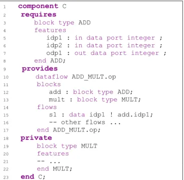
Syntactically, the parameters of a block are specified after a requires clause, the publicly visible elements made available by the block follow in a provides clause, and there may be a private part, as shown in Fig.7.
1 component C 2 requires
3 block type ADD 4 features
5 idp1 : in data port integer ; 6 idp2 : in data port integer ; 7 odp1 : out data port integer ; 8 end ADD;
9 provides
10 dataflow ADD_MULT.op 11 blocks
12 add : block type ADD; 13 mult : block type MULT; 14 flows
15 s1 : data idp1 ! add.idp1; 16 -- other flows ...
17 end ADD_MULT.op; 18 private
19 block type MULT 20 features
21 -- ... 22 end MULT; 23 end C;
Figure 7: A parameterized component. This example reveals parts of the textual syntax of Synoptic, which in this case is more perspicuous than a graphical syntax. The component C requires (an instance of) a block, called ADD, that is characterized by a component type having a certain number of in and out ports. C provides a dataflow that is composed of two blocks, one of which is defined in the private part of C.
Parameterized blocks can be instantiated with elements that meet their typing constraints, in a large sense. In the case of simple parameter types (like integers), the typing constrains are evident. When instantiating a parameterized component having a parameter type P with a component C, the component C has to provide all the elements stipulated by the requires clause of P (but may provide more). Conversely, C may require some (but not necessarily all) the elements provided by P. Parameter instantiation is thus essentially contravariant. Some clauses of a component are not checked during instantiation, such as private.
Parameter types can be equipped with properties such as temporal properties. Instantiating these types gives rise to proof obligations, depending on
the underlying logic. In some cases, an exact match between the formal parameter component and the actual argument component is not required. In this case, a mechanism comparable to a type cast comes into play: Take, for example, the case of a component C20| triggered at 20Hz (as in Fig.6) that is
to be used by a parametric component C10| operating
at 10Hz. Component C20| can be used as argument
of C10|, and a default frequency splitter will be
synthesized that adapts the frequency of the C20| to
C10|.
5. Incremental design and refinement features
The Synoptic environment promotes a top-down approach including incremental design and refinement features. In first steps of design, Synoptic allows to describe an abstract model.
For instance, the designer can describe abstract interfaces where data ports are not typed and connect instances of these interfaces in a dataflow diagram.
In a second step, the designer can refine its modelling by typing the block interfaces. The block interface can be then implemented with dataflow or automaton blocks. These features of the Synoptic environment are mainly ‘edition refinement’ which allows the designer to model a system in an incremental way. In doing so, the designer loses the link between the different levels of refinement: when the model is concretized, the initial abstract model is not preserved and therefore cannot be accessed.
Figure 8: AOCS nominal sub-mode.
Synoptic offers a way to specify refinement and to keep a formal link between an abstract model and its concretization. As depicted in the metamodel, Synoptic provides two types of refinements: flow
refinement and block refinement, Fig.8.
A flow refinement consists of refining a flow with a dataflow block. To be properly defined, the flow must be declared as abstract and the dataflow block must have a single input port and a single output port correctly typed.
A block refinement consists of refining a block instance with a dataflow block. The main use of this type of refinement is to concretize an interface block with a dataflow.
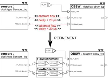
Example. Fig. 9 illustrates a flow refinement. The
first model is an abstract view of the global architecture of the case study.
Figure 9: Flow refinement.
The abstract model consists of three dataflow blocks. Sensors send their data (position and attitude) to the central flight software. OBSW computes them and sends a new command to actuators. In this abstract block diagram, flows between actuators and the OBSW are obviously not synchronous signals: data are exchanged through an 1553 bus.
To consider this fact, flows are specified as abstract. The same applies to the flows between OBSW and actuators. Moreover, a real-time requirement is added to the flows: <<delay ≤ 20 µs >>.
This requirement represents the maximum age of data: data consumed by OBSW must be aged less than 20µs. The second model shows how this abstract model is refined. Each flow is refined with a dataflow block composed of external variables. The concrete model confirms that data sent by the sensors are not synchronous flows but pass through the middleware. According to the real-time requirement of abstract model, the middleware is in charge of distributing data to flight software by respecting the limit of data aging. In addition, this refinement step displays the OBSW synchronous island.
6. Conclusion
The Synoptic language is equipped with tools based on the Eclipse EMF modeling framework. The purpose of the SPaCIFY project is not to develop a fully-integrated design environment but rather to equip the proposed design process with prototype tools in order to prove the feasibility of the approach. The development of the Eclipse-based modeling workbench started with the definition of the Ecore meta-model of the Synoptic language. The definition of this meta-model has relied on the experience
gained during the GeneAuto project. This definition is the result of a collaborative and iterative process. A concrete syntax relying on the meta-model has been defined using academic tools such as TCS (Textual Concrete Syntax). This textual syntax was used to validate the usability of the language through a pilot case study described in this paper. These models have helped to improve the Synoptic language and to adapt it to industrial know-how. Once the language was stabilized, a graphical user editor was designed. A set of structural and typing constraints have been formalized, encoded in OCL (Object Constraint Language), and integrated into the environment.
Along these activities, a formal semantics of the language was defined. The semantics of the functional part of the Synoptic language has been encoded in a typed sets theory using the B Method. This formalization has been performed in an incremental way. First, the Semantic Domain (SD) has been formalized. Our SD relies on the Model of Sequences [22]. Then, we formalized an abstract syntax of the Synoptic language. Finally, we have defined a semantics function associating to each node constructor of our abstract syntax a term expressed in the Sequences Model.
This formalization of the Synoptic semantics will be helpful to validate the existing transformation of Synoptic models to SME models. Another benefit of this semantics will be to establish links between Synoptic and other synchronous languages which semantics is expressed through the Tag Model [23]. We now plan to exploit this formalization framework in order to study the formalization of domain specific transformations from Synoptic to more and more concrete Synoptic models close to an actual implementation, e.g., taking into account scheduling and mapping aspects. We will rely mainly on the concept of refinement.
Case studies. The Synoptic environment is being
used to develop case studies of industrial size. Astrium intends to experiment the SPaCIFY technologies and tool chain. This case study targets on the one hand the evaluation of the Synoptic modeling language for early system engineering phases, and on the other hand the evaluation of the Altarica-based model-checker, especially with respect to its scalability. Thales Alenia Space conducts another case study which aims to model a complete flight software. This case study focuses on the use of external variables in the SPaCIFY design process, and on the use of the Polychrony platform for code generation purposes.
Future investigations. The Synoptic environment is
based on model transformation. Thus, verifying this transformations is a key point. It has been addressed in the Geneauto project to certify sequential code
generation from a Stateflow/Simulink based language. This work must be extended to take into account features of the execution platform such as timers, preemption-based schedulers, multi-threading, multi-processors,… Work is in progress on the functional subset of the Synoptic language. The Synoptic environment provides a toolset supporting a development process. Experience acquired during the SPaCIFY project with industrial partners has shed light two different processes and thus the need to parameterize the platform by the process. A SPEM-based specification of the development process could be used as input of a generic platform so that it could be configured to match end user current and future development methods. The Synoptic environment offers a limited support to refinement-based development process. This support could be extended and coupled with versioning to allow refinement checking between any couples of models or sub-models. It means a support for defining and partially automatically generating gluing invariants between models. Then proof obligations could be generated.
7. References
[1] Simulink: "Simulation and Model-Based Design”. http://www.mathworks.com/.
[2] Andres Toom, Tonu Naks, Marc Pantel, Marcel Gandriau, and Indra Wati: "GeneAuto: An Automatic Code Generator for a safe subset of SimuLink/StateFlow", In European Congress on Embedded Real-Time Software (ERTS’08), Toulouse, 2008
[3] F.-X. Dormoy: "Scade 6: a model based solution for safety critical software development", In Proceedings of the 4th European Congress on Embedded Real Time Software (ERTS ’08), Toulouse, 2008.
[4] RT-Builder : solutions for Real-Time design, modeling and analysis of complex, multiprocessors and multi-bus systems and software.http://www.geensys.com/?Outils/RTBuild er.
[5] Peter J. Robinson: " Hierarchical object-oriented design",. Prentice-Hall, Inc., Upper Saddle River, NJ, USA, 1992.
[6] Object Management Group: "CORBA Component Model 4.0 Specification". Specification Version 4.0, April 2006.
[7] Jean-François Rolland, Jean-Paul Bodeveix, Mamoun Filali, David Chemouil, and Thomas Dave: "AADL modes for space software", In Data Systems In Aerospace (DASIA), ESA Puhblications, 2008.
[8] As-2 Embedded Computing Systems Committee SAE: "Architecture Analysis & Design Language (AADL)", SAE Standards no AS5506, November 2004.
[9] Sanford Friedenthal, Alan Moore, and Rick Steiner: "A Practical Guide to SysML: The Systems Modeling Language", Morgan Kaufmann Publishers Inc., San Francisco, CA, USA, 2008. [10] Object Management Group: "A UML Profile for
MARTE, Beta 2", Technical report, June 2008. [11] ASSERT Project: Automated proof-based System
and Software Engineering for Real-Time Systems, http://www.assert-project.net/, 2007. [12] N. Halbwachs, P. Caspi, P. Raymond, and D.
Pilaud: "The synchronous dataflow programming language LUSTRE". In Proceedings of the IEEE, pages 1305–1320, 1991.
[13] Paul Le Guernic, Pierre Talpin, Jean-Christophe Le Lann, and Projet Espresso: "Polychrony for System Design", Journal for Circuits, Systems and Computers. Special Issue on Application Specific Hardware Design., 12:261–304, August 2003.
[14] Alan Burns, Brian Dobbing, and Tullio Vardanega: "Guide for the use of the Ada Ravenscar Profile in high integrity systems". Ada Lett., XXIV(2):1–74, 2004.
[15] David Harel: "Statecharts: A visual formalism for complex systems", Sci. Comput. Program., 8(3):231–274, 1987.
[16] Altarica Project. http://altarica.labri.u-bordeaux.fr/wiki/.
[17] James Gosling, Bill Joy, Guy Steele, and Gilad Bracha: "Java(TM) Language Specification", 3rd Edition. Addison-Wesley Professional, 2005. [18] ESA, European Cooperation for Space
Standardization: "ECSS-E-70-41 - Telemetry & Telecommand - Packet Utilisation" , 2003. [19] SPaCIFY Project: Model-Driven Engineering and
Formal Methods for Critical Embedded Software. http://spacify.gforge.enseeiht.fr/
[20] A. Cortier, L. Besnard, J.P. Bodeveix, J. Buisson, F. Dagnat,, G. Garcia, J. Ouy, M. Pantel, A. Rugina, M. Streker, J.P Talpin: "Chapter : Synoptic - a domain-specific modeling language for space on-board application software.”, in Book Synthesis of embedded software - frameworks and methodologies for correctness by construction software Design, Edition Springer, 2010 (to appear).
[21] J-P. Talpin, J. Ouy, T. Gauthier, A. Cortier: "Modular interpretation of heterogeneous modeling diagrams into synchronous equations using static single assignment", in proceedings of the 10th International Conference on Application of Concurrency to System Design (AOCS’10), 2010.
[22] L. Besnard, T. Gautier, P. Le Guernic: "SIGNAL-V4: INRIA Version : Reference Manual", Research Report, 2008
[23] E. A. Lee and A. L. Sangiovanni-Vincentelli: "Comparing models of computation", In International Conference on Computer Aided Design (ICCAD'96), San Jose, USA, 1996.