Université de Montréal
Bioresorbable coronary stents: Non-invasive quantitative assessment
of edge and intrastent plaque – a 256-slice computed tomography
longitudinal study
Par
Evguenia Zdanovich
Programme de Sciences Biomédicales Faculté de Médecine
Mémoire présenté en vue de l’obtention du grade de maîtrise en Sciences Biomédicales, option Générale
Juillet 2019
Université de Montréal
Programme de Sciences Biomédicales Faculté de Médecine
Ce mémoire intitulé
Bioresorbable coronary stents: Non-invasive quantitative assessment
of edge and intrastent plaque – a 256-slice computed tomography
longitudinal study
Présenté par Evguenia Zdanovich
A été évalué par un jury composé des personnes suivantes Daniel Juneau Président-rapporteur Carl Chartrand-Lefebvre Directeur de recherche Samer Mansour Codirecteur Karl Sayegh
Résumé
Les bioresorbable stents (BRS), en français intitulés tuteurs coronariens biorésorbables, sont constitués d’un polymère biorésorbable, plutôt que de métal, et ne créent pas d’artéfacts métalliques significatifs en tomodensitométrie (TDM). Cela permet une meilleure évaluation de la plaque coronarienne sous ces tuteurs en TDM qu’avec les anciens tuteurs qui sont en métal. OBJECTIF: Évaluer l’évolution de la composition de la plaque, sa fraction lipidique (FL)— marqueur de vulnérabilité de la plaque, dans les 3 zones pré-tuteur (bord proximal), intra-tuteur et post- tuteur (bord distal), et le volume de la plaque entre 1 et 12 mois post-implantation de BRS. MÉTHODOLOGIE: Il s’agit d’une étude observationnelle longitudinale réalisée chez 27 patients consécutifs (âge moyen 59,7 +/- 8,6 ans) et recrutés prospectivement pour une imagerie par TDM 256-coupes à 1 et 12 mois post-implantation de BRS (35 tuteurs total). Les objectifs primaires sont: volume de plaque totale et de FL (mm3) comparés entre 1 et 12 mois. Afin de tenir compte de la corrélation intra-patient, des analyses de variance des modèles linéaires mixtes avec ou sans spline sont utilisés avec deux facteurs répétés temps et zone/bloc (1 bloc= 5 mm en axe longitudinal). La valeur % FL= volume absolu du FL/ volume total de la plaque.
RÉSULTATS: Notre analyse par bloc ou par spline n’a pas démontré une différence significative dans les volumes de plaque ou des FL dans les zones pre- intra- and post-tuteur entre 1 et 12 mois.
CONCLUSION: Notre étude a réussi à démontrer la faisabilité d’une analyse non-invasive quantitative répétée de la plaque coronarienne et de la lumière intra-tuteur avec l’utilisation de TDM 256 coupes. Cette étude pilote n’a pas démontré de différence significative dans les volumes des plaques et atténuation entre 1- et 12- mois de follow-up post-implantation de BRS. Notre méthode pourrait être appliquée à l’évaluation des différents structures ou profils pharmacologiques de ces tuteurs.
Mots-clés : Tuteur biorésorbable, athérosclérose coronarienne, angiographie par tomodensitométrie, plaque coronarienne, fraction lipidique, volume, analyse de variance, modèle linéaire mixte, humains
Abstract
Coronary bioresorbable stents (BRS) are made of a bioresorbable polymer rather than metal. Unlike metallic stents, BRS do not produce significant artifacts in computed tomography (CT) and are radiolucent in CT, making it possible to evaluate coronary plaque beneath an implanted stent. PURPOSE: The purpose of our study was to evaluate the volumes of plaque and low attenuation plaque components (LAP —a marker of plaque vulnerability) of pre-, intra- and post-stent plaque location between 1 and 12 months post-implantation.
METHODS: In our prospective longitudinal study, we recruited 27 consecutive patients (mean age 59.7 +/- 8.6 years) with bioresorbable stents (n=35) for a 256-slice ECG-synchronized CT evaluation at 1 month and at 12 months post stent implantation. Total plaque volume (mm3) as well as absolute and relative (%) LAP volume per block in the pre-, intra- and post-stent zones were analyzed; comparison of 1 and 12 months post BRS implantation. Changes in these variables were assessed using mixed effects models with and without spline, which also accounted for correlation between repeated measurements with factors such as time and zone/block (1 block = 5 mm in longitudinal axis). The value % LAP= LAP absolute volume/ total plaque volume. RESULTS: Our block or spline model analysis showed no significant difference in plaque or LAP volumes in pre-, intra- and post-stent zones measured at 1 month and at 12 months.
CONCLUSION: Our study demonstrates the feasibility of repeated non-invasive quantitative analysis of intrastent coronary plaque and in-stent lumen using a 256-channel CT scan. This pilot study did not show significant differences in plaque volume and attenuation between 1- and 12- month follow-up from stent implantation. The method we used could be applied to the evaluation of different stent structures or different pharmacological profiles of bioresorbable stents.
Keywords : Bioresorbable stent, coronary atherosclerosis, computed tomography angiography, coronary plaque, low-attenuation plaque, volume, analysis of variance, mixed effects model, humans
Table of contents
Résumé ... 5 Abstract ... 7 Table of contents ... 9 Tables list ... 15 Figures list ... 17 Boxes list ... 20 Abbreviations list ... 21 Symbols list ... 27 Remerciements ... 31 Introduction avant-propos ... 33Chapter 1 – Coronary atherosclerosis ... 35
1.1. The epidemiology of coronary disease ... ... .. .. 36
1.2. Coronary anatomy ... 36
1.3. Arterial coronary micro-anatomy ... 38
1.4. Pathology of coronary artery disease ... 40
Chapter 2 – Coronary stents ... 47
2.1. Brief history of coronary artery obstructive disease treatment ... 48
2.3. History and hemodynamics of stenting ... 51
2.4. Stent types ... 52
2.4.1. Bare-metal stents ... 52
2.4.2. Drug-eluting stents ... 54
2.4.3. Bioresorbable stents—an avant-propos ... 55
2.5. A primer on bioresorbable stents ... 58
2.5.1. Bioresorbable stent composition ... 58
2.5.2. Bioresorbable stent lifespan and other related timelines ... 59
2.5.3. Clinical outcomes of bioresorbable stents ... 65
2.5.4. Bioresorbable stent complications ... 78
2.5.4.1. Side branch complications in bioresorbable stents ... 78
2.6. Imaging bioresorbable stents ... 82
2.6.1. Bioresorbable stent imaging with conventional coronary angiography ... 83
2.6.2. Bioresorbable stent imaging with intravascular ultrasound ... 84
2.6.3. Bioresorbable stent imaging with optical coherence tomography ... 86
2.6.4. Bioresorbable stent imaging with CT scan versus metallic stents ... 87
Chapter 3 – Cardiac computed tomography ... 91
3.1. Introduction to CT scan ... 92
3.2. Physical and technical principles of coronary CT scan ... 95
3.2.1. Temporal resolution in coronary CT scan ... 95
3.2.1.1. Retrospectively ECG-gated helical acquisition ... 96
3.2.1.2. Prospectively ECG-gated axial acquisition ... 97
3.2.2. Spatial resolution in coronary CT scan ... 98
3.2.3. Artifacts in coronary MDCT: detection and solutions ... 99
3.2.3.1. Motion artifacts ... 99
3.2.3.1.1. Cardiac motion ... 100
3.2.3.1.2. Respiratory motion ... 107
3.2.3.2. Metal or streak artifacts ... 108
3.2.4. Cardiac CT radiation ... 109
3.3. CT imaging of coronaries ... 109
3.3.1. CT imaging of native coronary arteries ... 110
3.3.2. CT imaging of coronary stents at present ... 111
Chapter 4 – Imaging coronary plaque ... 113
4.1. Imaging coronary lumen and plaque ... 114
4.1.1. Coronary CT imaging in action ... 114
4.1.2. CT-based plaque composition and morphology imaging ... 115
4.1.3. CT-based intrastent plaque imaging ... 118
4.1.5. CT-prediction of intrastent stenosis with plaque markers ... 124
4.1.6. IVUS and CT studies of intra- and juxta-BRS plaque ... 129
4.1.6.1. IVUS studies of intra- and juxta-BRS plaque imaging ... 129
4.1.6.2. CT studies of intra- and juxta-BRS plaque imaging ... 131
Chapter 5 – The essence of my work ... 135
5.1. Introduction and hypothesis ... 136
5.2. Methods ... 137
5.2.1. Study design ... 137
5.2.2. Ethical considerations ... 137
5.2.3. Study patients ... 137
5.2.3.1. Novel implantation protocol ... 138
5.2.3.2. CT study patients ... 138
5.2.4. CT imaging ... 139
5.2.4.1. Patient preparation ... 139
5.2.4.2. CT acquisition protocol ... 139
5.2.4.3. Contrast administration protocol ... 139
5.2.4.4. CT image reconstruction and post-processing ... 139
5.2.4.5. Radiation dose ... 140
5.3. Results ... 143
5.3.1. Study patients ... 143
5.3.2. CT plaque analysis ... 150
5.3.2.1. Plaque volume analyses ... 150
5.3.2.2. LAP volume analysis ... 152
5.3.2.3. Relative LAP (%) analysis ... 154
5.4. Discussion ... 156
Conclusion and Perspectives ... 161
Bibliography ... 163
Tables list
Table 1. Bioresorbable stent clinical outcomes: comparison with drug- eluting metallic stents
Table 2. BRS CCTA imaging: assessment parameters of the intrastent lumen and arterial walls
Table 3. CT-based parameters measured in BRS-stented coronary arteries in recent studies
Table 4. CT-based vulnerability markers of in-stent restenosis
Table 5. Plaque area change assessments under bioresorbable stents by IVUS
Table 6. Stent distribution parameters Table 7. Patient demographics
Table 8. Scan parameters
Table 9. Pre-implantation lesion characteristics as assessed with conventional angiography
Table 10. Description of the different sizes of BRS in our study
Table 11. Plaque volume at 1- and 12-month follow-up by block location (pre-, intra 1-, 2-, 3-, 4-, 5-, and post-stent blocks)
Table 12. Plaque volume at 1- and 12-month follow-up by plaque
Table 13. Absolute LAP volume at 1- and 12-month follow-up by block location (pre-, intra 1-, 2-, 3-, 4-, 5-, and post-stent blocks) Table 14. Absolute LAP volume at 1- and 12-month follow-up by plaque
location (pre-, 1st, 2nd, 3rd intrastent tertiles, and post-stent blocks) Table 15. Relative LAP volume at 1- and 12-month follow-up by block
location (pre-, intra 1-, 2-, 3-, 4-, 5-, and post-stent blocks) Table 16. Relative LAP volume at 1- and 12-month follow-up by plaque
Figures list
Figure 1. Coronary anatomy with 256-slice ECG-gated coronary CT scan angiography Figure 2. A cross-sectional view of coronary vessel composition
Figure 3. Current understanding of coronary lesion players in atherosclerosis development leading to vulnerable plaque
Figure 4. Depiction of progressive changes in the atherosclerotic artery leading to lumen narrowing and positive remodeling
Figure 5. Plain old balloon angioplasty
Figure 6. Percutaneous coronary intervention
Figure 7. Plasticised bare-metal cobalt-chromium stent Figure 8. CT imaging of bare-metal cobalt-chromium stent Figure 9. Drug-eluting in-stent restenosis
Figure 10. ABSORB bioresorbable stent
Figure 11. Composition and structure of ABSORB BRS and XIENCE V
Figure 12. Histological and optical coherence tomography evolution in resorption of ABSORB BRS in a porcine coronary arteries model
Figure 13. Longitudinal coronary healing process beneath bioresorbable scaffold captured in 5-year long imaging of the stented stenotic are
Figure 15. Outcomes from the three potential non-inferiority clinical trials Figure 16. Neointimal bridge formation after bioresorbable stent implantation Figure 17. Coronary catheterization room in Hôtel-Dieu Hospital in 2016 Figure 18. Conventional coronary angiography
Figure 19. Intravascular ultrasound post-implantation of a BRS in a patient with severe stenosis of mid left anterior descending artery
Figure 20. Bioresorbable scaffold struts visualization with OCT, after BRS
implantation in a patient with severe stenosis of mid left anterior descending artery
Figure 21. Reduced stent blooming artifacts and improved strut definition with sharp (XCD) in comparison to smooth (XCB) kernel
Figure 22. Bioresorbable stent visualized in mid-circumflex artery Figure 23. CT angiography correlation with conventional angiography Figure 24. Spiral or helical CT scanner
Figure 25. Prospectively and conventional retrospectively ECG-gated dual source CT Figure 26. Cardiac motion artifact
Figure 27. Illustration of the image acquisition of dual-source computed tomography with two x-ray tubes and corresponding detectors positioned at 90° angles
Figure 29. Radiation-induced DNA damage can lead to either damage tolerance or DNA repair and regulatory responses mechanisms activation
Figure 30. Non-invasive atherosclerotic plaque imaging
Figure 31. Computational simulation of FFR volume rendering of left coronary artery tree Figure 32. Calculating remodeling index of BRS-scaffolded coronary artery based on CCTA
imaging
Figure 33. CCTA BRS imaging: plaque volume assessment with TeraRecon software Figure 34. Pre-, intra- and post-stent zones composition with 5-mm blocks
Figure 35. Volumetric plaque analysis Figure 36. Intrastent stenosis
Boxes list
Box # 1 A reminder on the anatomy of the coronary arteries Box # 2 Thin-cap fibroatheroma
Box # 3 Arterial remodeling Box # 4 Spotty calcifications Box # 5 Stent
Box # 6 Neointimal hyperplasia Box # 7 Drug-eluting balloons (DEBs) Box # 8 Arterial vasomotion
Box # 9 Dual anti-platelet therapy Box # 10 Non-inferiority trials Box # 11 Temporal resolution Box # 12 Pitch
Box # 13 Spatial resolution Box # 14 Voxel
Box # 15 Dual-source CT scanner Box # 16 Attenuation
Box # 17 Radiation recommendations Box # 18 FFR and FFRCT
Abbreviations list
ACC
A
— American College of Cardiology
Ach — acetylcholine
ACS — acute coronary syndrome AHA — American Heart Association ASA — acetylsalicylic
AUC — area under the curve
BMS
B
— bare-metal stent
BMI — body mass index
BRS — bioresorbable stents (also known as BVS – bioresorbable vascular scaffolds)
CABG
C
— coronary artery bypass graft CAC — coronary artery calcification CAD — coronary artery disease
CCA — conventional coronary angiography CCTA — coronary CT angiography
CE mark — certification mark
CHUM — centre hospitalier de l’Université de Montréal CMR — coronary (or cardiac) magnetic resonance imaging
CT — computed tomography
Cx or LCx — circumflex coronary artery or left circumflex coronary artery
DEBs
D
— drug-eluting balloons DES — drug-eluting stents DNA — deoxyribonucleic acid DPL — dose-length product
ECG
E
— electrocardiogram EES — everolimus-eluting stent ESC — European Society of Cardiology
FDA
F
— Food and Drug Administration FFR — fractional flow reserve
FFRCT — fractional flow reserve computed tomography
F/U — follow-up
HR
H
— hazard ratio
I
ISR — in-stent restenosis IR — iterative reconstruction IVUS — intravascular ultrasound
LAD
L
— left anterior descending coronary artery LCX — left circumflex coronary artery
LDL — low-density lipoprotein LM — left main coronary artery
M
MACE — major adverse cardiovascular events MI — myocardial infarction
MLA — minimum lumen area
MLD — minimal lumen diameter MPR — multiplanar review
MRA — magnetic resonance angiography MRI — magnetic resonance imaging MSCT — multi-slice computed tomography mTOR — mammalian target of rapamycin
O
OR — odds ratio
PCI
P
— percutaneous coronary intervention PDA — posterior descending coronary artery PDLLA — poly (DL)-lactide
PO — per os
POBA — plain old balloon angioplasty
QCA
Q
— quantitative coronary angiography
R
RAMQ — Régie de l’assurance maladie du Québec RCA — right coronary artery
SD
S
— standard deviation
T
TCFA — thin-cap fibroatheroma TLF — target lesion failure
TVMI — target vessel myocardial infarction
U
USA — United States of America
VH-IVUS
V
Symbols list
bmp — beats per minutecm — centimeter Dr — doctor Gy — gray HU — Hounsfield unit Inc. — incorporated kVp — kilovolt peak mAs — milliamperes mg — milligram mGy — milligray mL — milliliter mm — millimeter mo — month ms — millisecond mSv — millisieverts p — page
two-dimensional 2-D —
3-D — three dimensional μm — micrometer
Remerciements
Je remercie sincèrement mon directeur principal, Dr Carl Chartrand-Lefebvre, mon co-directeur, Dr Samer Mansour, et mon parrain de maîtrise, Dr An Tang, pour:
M’avoir aidé avec la recherche de bourse de maîtrise. M’avoir initié aux congrès internationaux et
M’avoir appris comment les choisir pour le bien de mon intérêt. Avoir amélioré mon raisonnement scientifique.
M’avoir donné un avant-goût de gestion de mon projet. Avoir amélioré ma collaboration scientifique et mon autonomie.
M’avoir rendu plus déterminée à réussir mes projets. Avoir validé de mes travaux.
Avoir amélioré mon sens de travail accompli.
M’avoir beaucoup appris sur la priorisation et valorisation de mon travail et mon temps. Surtout un grand merci de m’avoir appris comment trouver mon style de composition scientifique. Au plaisir de travailler avec vous de nouveau.
Mes remerciements à Mme Sylvie Babin pour son aide administrative dans la gestion de mon dossier et son souci d’accompagner les étudiants du département de radiologie dans leurs diverses démarches.
Je remercie Charbel Naim, le fellow en cardiologie de Dr Mansour, pour m’avoir fourni et assisté avec les informations nécessaires pour amorcer mon projet de recherche.
Merci également à M. Miguel Chagnon pour m’avoir appris à avoir un raisonnement statistique et être disponible pour le support logistique.
Mes remerciements à Mme Assia Belblidia pour son prompte aide et ses démarches devant le comité d’éthique.
Je remercie aussi notre biostatisticien, le chirurgien cardiaque et PhD en statistique, Dr Louis- Mathieu Stevens, de nous être venu à la rescousse vers la fin de mon projet de maîtrise pour nous aider avec nos démarches statistiques rendues complexes et pour améliorer mes connaissances en statistiques.
Mes remerciements à Dr Daniel Juneau et Dr Karl Sayegh qui j’ai eu le privilège d’avoir en tant que président et membre du jury de mon mémoire de maîtrise.
Finalement, un grand merci à mes parents, Ирина Глазкова и Виктор Зданович, et mes proches pour tous les sacrifices qu’ils ont fait pour m’aider à devenir qui je suis aujourd’hui. Vous êtes toujours avec moi, même à des kilomètres.
Ma reconnaissance infinie va à mon conjoint, , pour m’avoir donné de l’assurance de persévérer et un exemple de l’estime de soi ainsi que le courage de s’aimer et pour simplement avoir été à mes côtés.
Introduction avant-propos
This master’s thesis manuscript begins with four chapters introducing an amalgam of concepts from cardiology and radiology—two disciplines I enjoy—with a focus on coronary atherosclerosis, coronary stents, cardiac computed tomography, and coronary plaque imaging. These introductory chapters accompany the reader to the main master’s project in chapter 5: a prospective longitudinal study performed on novel coronary bioresorbable stents and imaged by cardiac CT scan.
Chapter 1 – Coronary atherosclerosis
Presentation and objectives:This chapter will introduce basic concepts pertaining to coronary atherosclerosis. First, a brief review of coronary artery disease epidemiology will be presented. Second, coronary anatomy will be depicted using computed tomography. Third, the American Heart Association coronary artery plaque classification system will be discussed. Lastly, the notion of coronary plaque vulnerability will be addressed.
1.1. The epidemiology of coronary disease
Despite advances in the medical field, coronary artery disease (CAD) remains one of the most prevalent causes of morbidity and mortality throughout the world.1 In 2012, cardiovascular diseases resulted in 17.3 million deaths throughout the world despite unceasing improvement in the CAD survival rate. By 2030, this mortality rate is expected to increase to more than 23.6 million.2
In the United States, 50% of middle-aged men and 30% of middle-aged women will develop CAD of some type.3 However, from 1980 to 2002, CAD death rates fell by 52% in men and by 49% in women over 35 years of age.4 When addressing CAD risk factors, such as unhealthy diet, smoking, hypertension, obesity, high fasting plasma glucose, and physical inactivity, coronary artery disease tends to be preventable.3
1.2. Coronary anatomy
Usually, the proximal aorta gives rise to the left coronary artery which originates from the left posterior aortic sinus, and the right coronary arteries, which originates from the anterior aortic sinus.5 The left and right coronary arteries give rise to vessels that run partially though the main epicardial grooves, namely the left and right atrioventricular grooves and the anterior or posterior interventricular grooves (see box #1, p.38). The caliber and length of the coronary vessels and their side branches vary considerably.6
The proximal portion of the left coronary artery is called the left main coronary artery (LM) and is 0-15 mm in length. In most cases, the LM bifurcates into the left anterior descending coronary artery (LAD) and the left circumflex coronary artery (LCX), however, in 30% of the population, the LM trifurcates into an intermediate branch (also known as the ramus medianus) originating between the LAD and the LCX.6
and vascularize the lateral and posterior of the left ventricle (LV) and the left atrium. In case of left dominance, the LCX gives branches to vascularize the inferior portion of the LV. The anterior, anteroseptal and anterolateral left ventricular segments are nourished by the LAD and its branches.6 In case of left dominance, the LCX gives branches that vascularize the infero-posterior wall of the LV7.
The LCX runs through the left atrioventricular groove with its major side branches, which are obtuse marginal branches (generally one to three) that irrigate the lateral and posterior portions of the left atrium and left ventricle if there is left-side dominance.6
The right coronary artery (RCA) runs in the right atrioventricular groove. The RCA gives rise to the acute marginal artery and the right posterior descending artery (PDA). In case of right dominance, the RCA irrigates the inferior, posterior and interventricular septum.6 In 7% of the population prevails co-dominance8, which means that both LCX and RCA supply the inferior wall of the left ventricle9.
1.3. Arterial coronary micro-anatomy
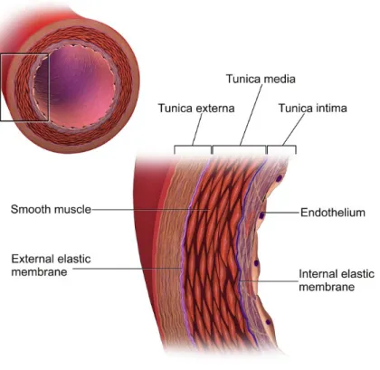
Coronary arteries are composed of three layers: the tunica intima, tunica media, and tunica adventitia (see fig. 2, p.39). The most inner layer of the coronary vessel is the tunica intima, which is composed of an endothelial layer that offers a frictionless surface for blood movement.11 The tunica media is the middle layer and consists of smooth muscle cells and elastin, which modulate the internal diameter of the coronary artery. The tunica adventitia (or tunica externa) is the most external layer that contributes to vessel shape and gives structural support.11
Box # 1
A reminder on the anatomy of the coronary arteries10
Figure 1. Coronary anatomy from 256-slice ECG-gated coronary CT scan angiography. Copyright © 2018 [CHUM, E Zdanovich]
Figure 2. A cross-sectional view of the composition of a coronary vessel.
Reprinted with permission from Wikimedia Foundation, Inc; Blausen.com staff (2014) WikiJournal of Medicine [Creative Commons Attribution-ShareAlike] (2014), DOI:10.15347/wjm/2014.010 ISSN 2002-4436 12License terms https://creativecommons.org/licenses/by-sa/3.0/
Coronary arteries supply organs with blood and nutrients and function under high pressure. This high pressure is accommodated by a greater ratio of elastic to muscle tissue. As previously described, the tunica media has elastic fibers. Likewise, the membrane between the tunica media and adventitia is also composed of an elastic connective tissue called the external elastic lamina or membrane. There is also an internal elastic membrane between the tunica intima and media
The size of a coronary vessel can be presented using a variety of parameters, such as minimal and maximal luminal diameters or cross-sectional area. The coronary vessel can be visualized and evaluated along its long or short axis. Coronary arteries are usually not perfectly round in their circumference; therefore, in a coronary cross-section (short-axis view), minimal and maximal diameters can be specified. When luminal diameter is measured, three diameters can be obtained: the minimal, mean and maximal luminal diameters. Cross-sectional area refers to the area of a given cross-section of the coronary vessel. The cross-sectional area of any components of the vessel, for example, a lumen or the external elastic membrane, can be measured.
1.4. Pathology of coronary artery disease
In 1856, Rudolph Virchow described how injury to an artery could lead to atherosclerosis of that vessel.13 Subsequently, in 1977, Russell Ross described a process of coronary atherosclerosis formation in which endothelial wall injury led to platelet adhesion to the wound, with activation of intimal smooth muscle cell proliferation resulting in plaque progression.13,14 Ross described atherosclerosis as an excessive inflammatory-proliferative process in the arterial wall, involving numbers of growth factors and vasoactive molecules.14
In the late 1990s, Libby and Hansson hypothesized on a complex interaction between clinical risk factors, such as hypercholesterolemia, innate and adaptive immunity status, and atherogenesis.15-17 In parallel, a complementary theory of plaque progression emerged due to the work of Fuster et al.18 The latter authors described atherogenesis as a series of events where endothelium is injured first, followed by denudation of the endothelial layer and damage to the intima, which then leads to further media damage in the advanced stages of the disease.18 In the same period of time, a new theory of atherogenesis emerged, which hypothesized that fissures in plaque led to coronary thrombosis and occurred mainly in soft, lipid-rich plaques covered with a thinning fibrous cap.19
In 1995, an expert committee from the American Heart Association (AHA) proposed a histological classification of coronary atherosclerotic lesions, from type I to type VI, from least to most clinically consequential.20 Type I represents initial intimal thickening. In type II, there is formation of a fatty streak composed of macrophages and lipid-rich smooth muscle cells. Type III is an intermediate state of atheroma that may be associated with clinical symptoms. In type IV, the lipid-rich core of the atheroma becomes more confluent and vulnerable. Type V is called fibroatheroma and is characterized by the presence of fibrous connective tissue. Type VI lesions can be either calcified or fibrosed. Such lesions tend to fissure and lead to hematoma.20
However, the concept of precursor lesions that would lead to clinical events was not addressed in the aforementioned classification of types of AHA lesion.1,21 Structural plaque characteristics and plaque vulnerability were subsequently studied and described with the following terms: adaptive intimal thickening, intimal xanthoma or fatty streak, pathological intimal thickening and fibroatheroma.1,20-22 It has also been revealed that the presence of a large necrotic core, an acellular lipid-rich milieu like that found in a vulnerable thin-cap fibroatheroma can convert a stable asymptomatic lesion into an unstable plaque with the potential to rupture.23 Therefore, the notion of thin-cap fibroatheromas (TCFA) arose and was subsequently associated with plaque vulnerability (box # 2, p.44).1,24 It was found that as TCFA grows, vessel lumen does not always narrow, since a vessel can exhibit adaptive positive remodeling, which can, like TCFA, also be a plaque vulnerability marker (box # 3, p.45).25 Finally, spotty calcification (defined as foci of calcifications measuring 3 mm or less) is another potential plaque component and marker that can be associated with plaque vulnerability (box # 4, p.46)26.
Plaque healing was also not addressed in the AHA classification. Healing of the ruptured plaque can lead to sequelae such as a rise in plaque burden (where cross-sectional areas of plaque and media are divided by the vessel’s external elastic membrane27), negative remodeling (see box # 3, p.45) leading to luminal narrowing, or chronic total occlusion.1,22
atherogenesis (e.g., vasa vasorum proliferation).28 These authors stated that shear stress at a
given point in the coronary artery results in anarchic neovascularization of the vessel wall, leading to the formation of vulnerable plaque due to intraplaque hemorrhage and microvascular leakage of red blood cells, inflammatory cells, and lipid/lipoproteins. Figure 3 (p.43) illustrates some of the key components of the above-described generic vulnerable plaque.
Finally, it has been shown that inflammation prevails in the atherosclerotic region from early atherosclerotic lesions or “fatty streak” to acute plaque erosion and rupture.29 An association between acute myocardial infarction and inflammatory factors has been described in the literature for over 50 years, which is partly due to the latter’s role in plaque progression and rupture.30 Nonetheless, it is still unclear whether this correlation between atherogenesis and inflammation is of a causal nature or not, or if inflammation is merely the result of injured cardiac tissue.29 Low-density-lipid (LDL) cholesterol-lowering drugs called statins may have a role in reducing inflammation. Indeed, they directly decrease activity of a nuclear factor, which regulates inflammatory genes, while indirectly lowering free cholesterol and oxidized-LDL levels, which act as proinflammatory mediators.29
Figure 3. Current understanding of coronary lesion players in atherosclerosis development leading to vulnerable plaque. Vulnerability markers represented here include positive remodeling (oval shape of cross-section), necrotic core, and spotty calcifications, which can complicate via hemorrhage and/or thrombus.
SMCs = smooth muscle cells, which proliferate and maintain plaque formation and growth; LDL = low-density lipoprotein, which can migrate through intima and form lipid core with cholesterol crystals; MMPs = matrix metalloproteases, which upregulate matrix degradation and tend to switch from stable plaque to thin-cap fibroatheroma; macrophage = a kind of inflammatory cell; foam cells = macrophages that have engulfed lipid particles, which can accumulate and form a
Reprinted by permission from World of J Radiol: Progress in atherosclerotic plaque imaging by G. Soloperto and S. Casciaro © (2012 Baishideng Publishing Group Co.) Aug 28, 2012; 4(8): 353-371. Doi : 10.4329/wjr.v4.i8.353 25
Box # 2
Thin-cap fibroatheroma
As histological studies show, the most common type of vulnerable plaque is thin-cap fibroatheroma (TCFA). It consists of a lipid-rich necrotic core covered with a thin cap rich in macrophages, which are white blood cells that cleanse the body of foreign substances.31 TFCA is quantitatively characterized as an atheroma with a fibrous cap of <65 μm in thickness1,32 with a lipid-rich necrotic core representing about 35% of plaque volume, infiltrated with macrophages of >25 cells per 0.3 mm diameter field.33 Major predictors of acute coronary syndrome are the thickness of TCFA and the dimensions of the lipid-rich necrotic core.34
Box # 3
Arterial remodeling
Arterial remodeling occurs when atheromatous plaque in the coronary arteries expands. This remodeling can either expand the vessel outward, a process called positive remodeling, or shrink it inward, in negative remodeling.35
Positive remodeling represents a compensatory mechanism that initially protects the vessel lumen from the expanding intimal plaque and is therefore called adaptive positive remodeling.36,37 Later on in the life of atherosclerotic plaque, extensive positive remodeling can be considered a marker of plaque vulnerability, along with a large lipid core and increased macrophage lesion influx (inflammation markers).38,39 Exaggerated positive remodeling tends to be associated with plaque rupture and unstable coronary syndromes.35,40 As the Glagov principle states, coronary arteries enlarge with the growing plaque area, which delays functionally important lumen stenosis provided that the plaque area remains less than 40% of the internal elastic lamina area (fig. 4, below)37.
Remodeling index35 = External elastic membrane area at the lesion site
External elastic membrane of the reference
Figure 4. Depiction of progressive changes in the atherosclerotic artery leading to lumen narrowing and positive remodeling. With occurrence of positive remodeling, an almost normal lumen cross-sectional area is preserved with £40% stenosis. Reproduced with permission from the New England Journal of Medicine, Compensatory enlargement of
human atherosclerotic coronary arteries by Glagov S et al 1987; 316:1371-1375. Copyright Massachusetts Medical Society.37
Box # 4
Spotty calcifications
Atheromatous plaques of patients with acute coronary syndromes were shown to include small calcifications in a spotty pattern.41,42 Some studies have demonstrated that spotty micro-calcifications can bring an increase in biomechanical plaque stress, thus becoming one of the possible pathways to plaque rupture.43,44 Spotty calcifications can possibly activate inflammatory cytokines and fragilize plaque morphology, which can lead to local inflammation and plaque instability.26
Finally, under certain patient and plaque characteristics, coronary atherosclerosis can lead to plaque rupture, which in turn can result in luminal thrombosis. Addressing these characteristics that give rise to vulnerable plaque is currently an investigation target in the field of cardiovascular research.
Chapter 2 – Coronary stents
Presentation and objectives:This chapter will introduce the reader to coronary angioplasty and will describe the main types of coronary stents that are implanted to treat coronary stenosis in all settings of acute coronary syndrome or stable angina. Most of the chapter will discuss the novel bioresorbable stents. The composition of bioresorbable stents, the associated clinical outcomes and the imaging of these stents using modalities such as conventional coronary angiography, intravascular ultrasound, optical coherence tomography and computed tomography will be covered.
2.1. Brief history of coronary artery obstructive disease treatment
At the turn of the twentieth century, acute coronary artery disease (CAD) (or acute coronary syndromes) was difficult to treat. Bed rest, oxygen and intravenous fluids were the main treatments.With the 1980’s came the thrombolytic era45, during which thrombolytic agents such as streptokinase or tissue plasminogen activator were administered, dissolving coronary thrombus and restoring coronary blood flow.
Even when thrombolysis was successful, re-occlusions occured.46 Thus, despite improved clinical outcome with thrombolytic therapy, one third of patients did not gain adequate coronary reperfusion.47,48
There were also some contraindications to the use of thrombolytics, such as presence of active bleeding, recent surgery, uncontrolled hypertension and history of stroke. It was observed that patients of 75 years and older had side effects such as major risk of haemorrhagic stroke.47,49 By the end of the 1970’s, besides medical treatment, two major options of CAD treatment had evolved: 1) surgical coronary revascularization with bypass grafting; and 2) plain old balloon (no stent) angioplasty (POBA). Despite bypass surgery being an appealing alternative, POBA was also promptly adopted as a treatment of CAD.46,50,51
2.2. Percutaneous coronary intervention era
Cardiac catheterization is performed to diagnose and assess cardiac heart disease.52 Worldwide, this cardiac procedure is used widely. The term cardiac catheterization can be used for both right and left or either of the heart catheterizations. Interventional cardiologists perform this procedure either to diagnose or to treat the cardiac heart disease such as with POBA and PCI. The cardiac catheterization is conducted by inserting a catheter into the heart such as into a ventricle
definitive contraindications except for the relative contraindications that depend on the patient’s comorbidities.53
POBA was performed first on an awake patient by Dr. Andreas Gruentzig in 1977 in Zurich, Switzerland. Dr. Gruentzig also developed the first balloon inflation device51 (fig. 5, below). POBA mechanism in the treatment of MI and/or myocardial ischemia involves the compression and redistribution of the culprit atherosclerotic plaque, then improving the coronary artery lumen patency.54 However, work done on human cadavers and in vivo animal experiments have also suggested that during balloon deployment some changes were comprised of intima rupture and its separation from the media.55 Moreover, the limits of POBA are also represented by its critical risk factor—small vessel size.56
Figure 5. Plain old balloon angioplasty. A) Dr. Andreas Gruentzig and his lab; B) Gruentzig’s balloon catheter uninflated and inflated; and C) Gruentzig’s inflation device that was used to inflate the balloon catheter. Reprinted from “Tactile VR for hand–eye coordination in simulated PTCA”; YY Cai et al. Computers in Biology and Medicine 2006; 36: 167-180. Copyright (2018) with permission from Elsevier.57
Restenosis can happen after an angioplasty, is defined as the decrease in the diameter of the vessel lumen and frequently leads to the target lesion failure.58 Mechanisms of restenosis in POBA are comprised of vessel remodeling and elastic recoil.59
Studies showed less residual stenosis following POBA and higher rates of patency in the weeks after reperfusion in comparison to thrombolysis.46 POBA technique was nonetheless far from ideal. Up to 30-50% of patients, in the first year, had occurrences of restenosis, occlusions and early recoil.46
Another non-surgical procedure followed POBA called percutaneous coronary intervention (PCI), or also known formerly as angioplasty with stent, that with help of a catheter introduces a stent into a blood vessel to treat stenosis.60
Percutaneous coronary intervention can be performed through radial artery access with small- caliber catheters using the Seldinger technique (fig. 6, below) or through femoral artery access.
Figure 6. Percutaneous coronary intervention. A) Coronarography catheters. B) Radial artery intervention — Seldinger technique, radial artery. C) Inflated balloon catheter visualization during PCI. With permission from Dr. Carl Chartrand-Lefebvre 2017.
As opposed to POBA, in-stent PCI angioplasty restenosis is defined as excessive tissue proliferation also called neointimal proliferation. It is also defined by the atherosclerotic process of a novel occurrence named neoatherosclerosis.61 These notions were discussed in chapter 1 and will further be discussed in the current chapter.
Box # 5 Stent
The term “stent” comes from the name of Charles Thomas Stent (1807-1885), an English dentist who invented Stent’s dental compound.62 This compound was used by plastic surgeons in 1917 during the First World War to attach facial skin grafts to war wounds.63 In 1972, Goodwin et al. defined the term stent as “a compound (that holds) some form of graft in place”.62
2.3. History and hemodynamics of stenting
It was in March of 1986 that the first coronary stent was implanted by Jacques Puel and Ulrich Sigwart in Toulouse, France.62,64 In French, the “stent” became the “endo-prothèse coronarienne autoexpansive”. Nowadays, a vascular stent is also called, in French— a “tuteur”, a term used in botany for a stake that holds a plant straight.
The first coronary stents were invented by Julio Palmaz and Richard Schatz65 to circumvent two significant limitations of balloon angioplasty: acute elastic recoil and restenosis. The stent’s mechanical scaffolding supports the vessel and prevents early recoil, allowing a laminar flow and decreasing the shear stress on the vessel, which reduces intimal thickening. The struts of the stent also cover open subintimal spaces, thus preventing contact of the thrombogenic substrate with platelets and aggregating factors. This reduces the possibility of local thrombi formation and their incorporation into a restenotic lesion.66
Further developments happened in the mid- and late-1980’s.51 Early stents were far from ideal because of their thrombogenic potential.66 The three main categories of stents used in recent years are bare-metal stents, drug-eluting stents and bioresorbable stents. In the province of
approximately 15,630 coronary angioplasties were performed in a total of 15 centers practicing angioplasty.67
2.4. Stent types
A timeline of the different types of stents to be discussed in this chapter is presented as follows:
Timeline:
1986 – First implantation of bare-metal stent in a human coronary artery
1994 – FDA (Food and Drug Administration) approval of coronary stents for use in clinical settings
2002-2004 – Drug-eluting stent homologation by FDA51
2016 – FDA approval of the bioresorbable vascular scaffold68
2.4.1.
Bare-metal stents
As previously mentioned, the first intracoronary stent implantation was performed by Puel and Sigwart in 1986.62,64 A stainless-steel auto-expansive multifilament system without eluting medication was deployed. In the early 1980’s, stent implantation was reserved for patients with the following indications: restenosis after a successful initial angioplasty, acute vessel occlusion after balloon angioplasty (bail-out stenting), and stenosis of aorto-coronary bypass. The U.S. Food and Drug Administration (FDA) approved the use of coronary stents in clinical settings in 1994.51 Figures 7 and 8 on the next pages show modern cobalt-chromium bare-metal stents (BMS).
Dieu (patient information stand), CHUM 2017.
Figure 7. Plasticised bare-metal cobalt- chromium stent. With permission from
Hôtel-A large randomized controlled trial named the CHôtel-ADILLHôtel-AC trial (Controlled Hôtel-Abciximab and Device Investigation to Lower Late Angioplasty Complications), which enrolled 2082 patients with myocardial infarction (MI), demonstrated a lower death, revascularization, reinfarction, or stroke composite endpoint in patients who were implanted with a BMS in comparison to those treated solely with a POBA (11.5 vs. 20.0 %, p<0.001).69
Figure 8. CT imaging of a bare-metal cobalt-chromium stent. A 54-year-old man with a permeable cobalt- chromium bare-metal stent (4.0x20 mm) implanted into his right coronary artery (yellow arrow). This coronary angiogram was performed using a 256-slice CT scanner with ECG-synchronized acquisition (Brilliance iCT, Philips Healthcare, Best, The
Netherlands). Copyright © 2017 [E Zdanovich]
Left ventricle Right ventricle Right artery valve
2.4.2.
Drug-eluting stents
BMS implantation allowed a decreased number of urgent (recoil) and non-urgent revascularisation events in patients with PCI than in stand-alone POBA. However, in-stent restenosis was observed in 10-40% of patients by 6 months post-PCI due to neointimal hyperplasia (see box # 6, below).69 With the goals of reducing neointimal hyperplasia and improving clinical outcomes, drug-eluting stents were created.
Box # 6
Neointimal hyperplasia
Neointimal hyperplasia is defined as an increase in thickness in the intimal layer of the coronary artery, called neointima due to proliferation and migration of smooth muscle cells.70
Drug-eluting stents (DES) offer delayed release of an anti-proliferative drug such as sirolimus or paclitaxel from a strut coating that impedes proliferation of smooth muscle cells.70 In comparison to BMS, DES have been associated with lower rates of death, stent thrombosis, binary stenosis, target-vessel and target-lesion revascularization.69 However, a certain level of in-stent restenosis has been associated with DES (fig. 9, below).
There are two types of DES: first and second generation. The second generation is thinner, more deliverable, leads to less inflammation response and procures more rapid re-endothelialisation (vessel healing).71 Drug-eluting balloons (DEBs) will be discussed in box # 7, next page.
Figure 9. Drug-eluting in-stent restenosis. In-stent restenosis of about 50% (arrows) in a drug- eluting stent located in the right coronary artery of a 47-year-old woman. A) Curved multiplanar reconstruction; B) Orthogonal view of restenosis. Copyright © 2016 [C Chartrand-Lefebvre]
Box # 7
Drug-eluting balloons (DEBs):
DEBs recently emerged as yet another way of addressing restenosis. The balloons are usually coated with paclitaxel due to its rapid absorption and good retention.
2.4.3.
Bioresorbable stents—an avant-propos
Bioresorbable stents (BRS) are also commonly referred to as bioresorbable vascular scaffolds.51 In July 2016, the FDA approved the first bioresorbable vascular scaffold stent in the U.S.68 Recently, the European Society of Cardiology (ESC) / European Association of Percutaneous Coronary Interventions (EAPCI) stated that bioresorbable stent (BRS) is a more appropriate term than bioresorbable vascular scaffold (BVS), since a scaffold might suggest only a temporary need for coronary support.72
BRS offer potential advantages over their predecessors. After PCI, once the vessel is healed, there is potentially no further necessity for permanent vessel scaffolding and drug delivery. Permanent metallic stent implantation interferes with surgical revascularization, produces artifacts in non- invasive imaging and precludes reactive vasomotion (definition in box # 8, below).73
Box # 8
Arterial vasomotion: What is it?
A cyclic variation of the vessel diameter moderated by medial smooth-muscle cells, which react to vasoactive molecules of the endothelium such as acetylcholine and nitroglycerine.74,75
How is it measured?
A vasomotion test can be performed as follows:
Mean in-stent and distal lumen diameters are measured by quantitative coronary angiography (QCA, section 2.6.1) after sequential infusions of saline, 10-8, 10-7 and 10-6 M Acetylcholine (Ach), and a vasoconstrictor, through a microcatheter.76,77 Nitrate (200 mg), a potent vasodilator, is administered at the very end of the process to help the artery return to its natural vasoactive tone.
Vasoconstriction to Ach is established when there is >= 3% decrease in the lumen diameter from baseline (saline) after infusion of highest dose of Ach.76,78,79
The BRS soft scaffold preserves better physiologic vasomotion of the stented segment with the native angulation of the arterial curvature and shear stress, which becomes even more
physiologic after BRS resorption, thus reducing the atherogenic potential. It also allows late luminal gain and late expansive arterial remodeling80,81 (see section 2.5.2 for more details). Furthermore, once bioresorption is completed, lengthy dual anti-platelet therapy (see box # 9, below) can be discontinued, since the iatrogenic material is no longer present.80 Moreover, hypothetically, this would allow bypass grafts on stented segments.
Box # 9
Dual anti-platelet therapy consists of two agents:
1) Aspirin, or acetylsalicylic acid (ASA), which prevents thromboxane production by platelets and their agglomeration into clots.82 It is prescribed for those who have had a myocardial infarction, stenting procedure, or coronary artery bypass graft (CABG) surgery. Aspirin therapy is continued for the rest of the patient’s life.83
2) P2Y12 inhibitor, which irreversibly blocks the adenosine diphosphate P2Y12 receptor, to prevent platelet agglomeration. The P2Y12 inhibitor prescribed can be either clopidogrel, prasugrel, or ticagrelor. It is usually taken for months or years, concurrently with aspirin therapy.83
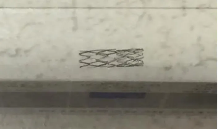
There are five bioresorbable stents that have received CE Mark approval in Europe. Among them are Absorb (Abbott Vascular), DESolve (Elixir Medical), ART Pure (ART) and Magmaris (Biotronik).84,85 Only Absorb has been approved in the U.S. and Canada.84,86 An Absorb bioresorbable stent in its deployed and non-deployed state is shown in figure 10 on next page.
Figure 10. Absorb bioresorbable stent. A) Deployed B) Not deployed, with platinum indicator visible. (Image modified) Reprinted from “Biodegradable vascular scaffold Absorb BVS™ - scientific evidence and methods of implantation”; Rzeszutko L, Depukat R, Dudek D, Postepy Kardiol Interwencyjnej 2013; 9(1): 22–30; Copyright (2018) with permission from Open Access article from Creative Common Public Domain.87
2.5. A primer on bioresorbable stents
2.5.1.
Bioresorbable stent composition
The Absorb and DESolve BRS, the bioresorbable stents used most frequently, are composed of a poly-L-lactic acid (PLLA) scaffold with a poly-D,L-lactic acid (PDLLA) coating88 (fig.11, below). These are each associated with an antiproliferative agent – everolimus in the Absorb model and novolimus in the DESolve model,76,80 which reduces proliferation of smooth muscle cells in the stented segment. Even though the struts in the Absorb BRS are thicker (157 µm) than in the Xience DES (89 µm), the dose densities of everolimus that the Absorb releases are similar to the Xience model (fig. 11, below).89
Figure 11. Composition and structure of the Absorb BRS and Xience V. Co-Cr = cobalt–chromium; PLLA = poly-L-lactide; PDLLA = poly-D,L-lactide; BVS= bioresorbable vascular scaffold (synonym of BRS). Reprinted from “Clinical Outcomes of Small Side Branch Occlusion After Implantation of Bioresorbable Vascular Scaffold”; T. Muramatsu et al., JACC Cardiovasc Int, 2013 Mar;6(3):247- 57, Copyright (2018) with permission from Elsevier.88
2.5.2.
Bioresorbable stent lifespan and other related timelines
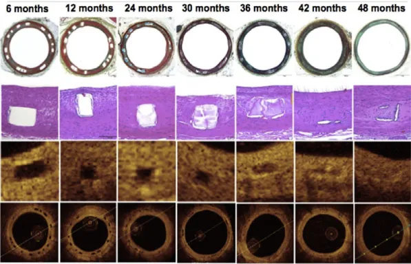
A BRS resorbs into the bloodstream after 2 to 3 years on average, in contrast to bare-metal or drug-eluting stents which will remain in the body throughout the patient's life (fig. 12, below).81,90,91 Optical coherence tomography (OCT) (see section 2.6) and histologic evaluation have been performed on porcine coronary artery models. At 6, 12 and 24 months post- implantation of BRS, struts appeared as acellular regions with well-circumscribed borders (fig. 12, first three columns). At 30 and 36 months, there were minimal to no residual polymer struts remaining.80,81 Histology shows that the original struts were replaced by an acellular provisional matrix and stained both Movat's pentachrome and hematoxylin-eosin. At 48 months, struts were barely visible and had become part of the surrounding tissue.
Figure 12. Histological and optical coherence tomography (OCT) evolution in resorption of ABSORB BRS in a porcine coronary arteries model. Movat's pentachrome (MP), 2X objective (top row) and hematoxylin and eosin (HE), 20X objective, top row center. Histological images show imperceptible to mild inflammation, no calcification of struts and no fibrin deposition. OCT images show struts as a preserved box at 6, 12, 24 and 30 months, then an open box at 36 months, a dissolved box at 42 months and an almost imperceptible box at 48 months. Reprinted from “Bioresorbable scaffold — A magic bullet for the treatment of coronary artery disease?” D. Brie et al. Int J. Cardiol 2016; 215: 47–59. Copyright (2018), with permission from Elsevier.80
The ABSORB Cohort B trial enrolled a total of 101 patients. Of this group, 45 patients were assigned to the Cohort B1 study and given 6-month and 2-year angiographic follow-ups, while 56 patients were assigned to Cohort B2 and given a 1-year angiographic follow-up. The ABSORB Cohort B1 and B2 studies have both provided up to 5-year follow-up intravascular imaging post BRS implantation, which gives objective data on scaffold resorption and coronary healing in patients. This data showed that coronary vasomotion was observed within 6-12 months post-
deployment, and an increase in lumen area with adaptive vascular remodeling (see box # 3, p.45) was observed close to 1 year post-deployment.75
It was also observed that after quantitative coronary angiography was performed at different points of time post-deployment of metallic stent, the coronary intra-stent minimal lumen diameter (MLD) progressively decreased.75
However, QCA post-deployment of the Absorb BRS showed lumen preservation, and even expansion, over time. Likewise, serial intravascular ultrasounds (IVUS, section 2.6.2) performed over time, post-implantation of the Absorb BRS, revealed an increase in stent and vessel area from 6-24 months. Such adaptive remodeling accommodates the observed increase in plaque area that subsequently decreases from 2-5 years (see fig. 13, next page).75,92
Figure 13. Longitudinal coronary healing process beneath bioresorbable scaffold captured in 5- year-long imaging of stented stenotic area.
Scaffold polymer resorption takes nearly 36 months. Mechanical support provided by the scaffold remains unchanged for up to 6 months. A 3-month elution of everolimus (a cytostatic agent) from the struts prevents excessive neointimal hyperplasia.
At close to 12 months, the scaffold’s mechanical support disappears and vasomotor tone begins to return. Such changes allow cyclical strain and physiological endothelial shear stress to again be transferred to the stented coronary wall (mechano-transduction), which becomes a possible mechanism for vessel remodeling.
At close to 24 months, scaffold expansion maintains lumen patency by compensating for neointimal growth. During this period, the vessel and plaque areas increase.
At close to 36 months, the lumen area remains unchanged, while the vessel and plaque area begin to decrease.
At close to 60 months, scaffold struts resorption and dissolution are complete and the void is filled with connective tissue. There is now a new layer of tissue between the lumen and the plaque, which is called the endoluminal tissue layer or neomedia.
Reprinted from “A Polylactide Bioresorbable Scaffold Eluting Everolimus for Treatment of Coronary Stenosis: 5-Year Follow-Up”; Serruys P.W. et al., J. Am Coll Cardiol., 2016 Feb 23;67(7):766-76. Copyright (2018), with permission from Elsevier.92
Thus, it has been observed that changes in vessel and plaque area with BRS accompany a preservation of, or even an increase in, mean lumen area (late lumen gain). OCT performed post- implantation over several time points demonstrates an early increase in stent area (from 6-12 months), in parallel to an early growth in the neointimal area, which helps to preserve the mean lumen area. Such late luminal preservation or even luminal gain post BRS deployment has been related to the gradual dissolution of scaffold struts and their replacement with a fibroelastic matrix (neomedia), which retracts over time and gives space for lumen normalization. This neomedia tends to seal plaques with a necrotic core, which could impede future plaque rupture.
Furthermore, the return of vessel vasomotor sensitivity to vasoactive stimuli (acetylcholine or nitroglycerine) is documented at 6-12 months after Absorb BRS implantation.75 After 5 years, coronary vasodilation in response to administered nitroglycerine was observed by QCA in more than 80% of Absorb BRS-containing vessels.75,93 However, coronary vasomotor sensitivity does not return post-deployment of a metal stent.75 The return to natural vasomotion of the vessels in the stented segment after implantation of bioresorbable stents allows for normalized arterial flow and shear stress.80,81
Figure 14. Plaque and vessel progression over time after implantation of metallic or bioresorbable stents.
(a) Longitudinal coronary healing response in metal versus bioresorbable stents.
(b) Neointimal appearance observation with optical coherence tomography following ABSORB BRS implantation.
A, B, C = healing process within 12 months following ABSORB BRS deployment. A', B', C' = zoom view (arrows) of the re-epithelized healing regions.
* = Necrotic core plaque. BVS = bioresorbable vascular scaffold.
Reprinted from “Bioresorbable vascular scaffolds for the treatment of coronary artery disease: What have we learned from randomized-controlled clinical trials?”, Rizik D. G. et al., Coron Artery Dis., 2017 Jan;28(1):77-89. Copyright (2018), with permission from Wolters Kluwer Health, Inc.75
2.5.3.
Clinical outcomes of bioresorbable stents
In earlier studies of BRS, reported clinical outcomes of BRS were similar to those of DES, with similar composite outcomes of target lesion revascularization, target vessel myocardial infarction and cardiac death events (table 1, p.67). For example, the ABSORB II trial – a single-blind, multicenter, randomized control trial performed by Serruys P.W. et al., compared clinical events with the everolimus-eluting BRS versus the everolimus drug-eluting stent (DES) in 501 patients, guided by intravascular ultrasound (IVUS).95 Between 2011 and 2013, the trial enrolled 335 patients with BRS (364 lesions) and 166 patients with metallic stents (182 lesions). Clinical outcomes with the BRS and DES were similar at the 1-year follow-up (respectively 5% vs. 3%, p=0.35). The thrombosis rate was also similar at 0.9% in the BRS and 0% in the DES (p=0.55) (see table 1, p.67). However, the authors of the ABSORB II study reported that generalizability of the study may be limited, since the lesions analyzed were simpler than in daily practice of cardiologists.
In the ABSORB II 3-year follow-up trial published by Serruys et al. in Lancet in 2016,96 there were 23 (7% of 325 study patients – 6% with the BRS Absorb vs. 1% with the DES Xience, p=0.0108) documented target vessel myocardial infarctions, of which 13 (5% – 4% with Absorb vs. 1% with Xience, p=0.16) were peri-procedural. Within 1 to 3 years of follow-up in the population of 329 study patients, there were a total of 6 (2%) definite very late scaffold thromboses documented in the Absorb group and none in the Xience group. The percentage of thrombosis out of the total number of stents was not indicated.96
In the ABSORB II 4-year follow-up study published by Chevalier et al. in EuroIntervention in 2018,97 follow-up at 4 years was conducted with 86% (288/335) of the initial cohort patients in the Absorb group and with 84% (139/166) of the Xience group. The target vessel myocardial infarction rate was not documented in this study, as it was in the 3-year follow-up. However, target lesion failure rate was reported to have increased from 10.5% to 11.5% in the Absorb group and from 5.0% to 6.0% in the Xience group between the 3- and 4-year follow-up with no statistical significance at 4-year rates (p=0.063). Between the 3- and 4-year follow-up, no additional very late scaffold or stent thrombosis was documented in either group. Overall, the 4-year rate of very late scaffold or stent thrombosis was 3.0% in the Absorb group and 0.0% in the Xience group (p=0.035) (visit table 1, p.67).
There are some limitations to the two aforementioned studies. The PCI surgeons were not as experienced with the implantation of the BRS scaffold as with metallic stents, and the optimum implantation techniques that are currently recommended were not yet known,98 which may have affected scaffold thrombosis rates. This study did not perform IVUS or OCT imaging analysis of very late scaffold thrombosis to understand its etiology. Further studies are needed to understand this mechanism.
Following the beginning of the ABSORB II trial, a large, multi-center, randomized control trial called ABSORB III enrolled 2008 patients with stable or unstable angina.99 These patients were randomly assigned in a 2:1 ratio to receive either an Absorb BRS scaffold (1322 patients) or an everolimus-eluting cobalt-chromium (Xience) stent (686 patients). The trial’s primary end point
revascularization, or target-vessel myocardial infarction) at 1-year post stent implantation. Also, in-scaffold and in-segment measurements were performed by quantitative coronary angiography.
Table 1. Bioresorbable stent clinical outcomes: comparison with drug-eluting metallic stents 95- 97,99-108
EES = everolimus eluting-stents (e.g., Xience); Ŧ Clinical outcomes (or major adverse cardiovascular
events also known as MACE) are reported as published, such as a composite of target lesion revascularization, target vessel myocardial infarction and cardiac death; DOCE = device-oriented composite endpoint ⌘Definite or probable thrombosis; mo = months; V Target lesion failure (TLF)
is measured and defined as a composite of cardiac death, myocardial infarction resulting from target vessel thrombosis, or ischemia-driven target lesion revascularization; CCEE- cobalt- chromium everolimus-eluting stent.
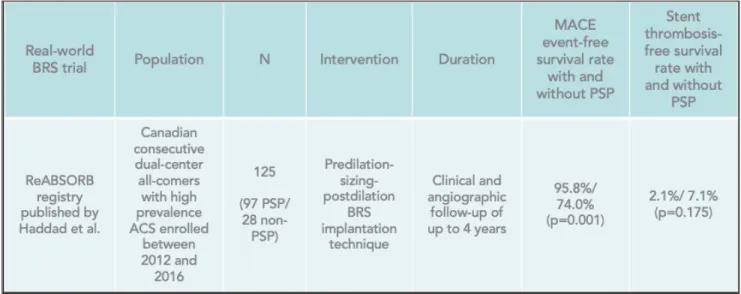
ACS = acute coronary syndrome. PSP = predilation-sizing-postdilation, a BRS implantation technique. Copyright © (2019) Evguenia Zdanovich.
The study showed non-inferiority of BRS for target lesion failure at 1-year follow-up (p = 0.007) with data collection still ongoing.99 At 1-year post implantation of stents, the percent thrombosis of stented segments was slightly higher with BRS than with DES, although it did not reach statistical significance (i.e., 1.5% vs. 0.7%, p=0.13)99 (see table 1, p.67).
Some limitations of the ABSORB III study were noted by the authors. For instance, the trial enrolled patients with relatively stable angina symptoms and simple coronary lesions. Thus, study findings may not be generalizable to patients with more complex coronary lesions. Finally, low- frequency events such as cardiac death or scaffold thrombosis were underpowered in this study. Therefore, interpretations of rates of such events should be carried out with caution, especially as pertaining to the non-significant difference between stents.99
In 2017, Kereiakes et al.102 published ABSORB III study results from a 3-year follow-up post stent implantation. The number of patients in each group (Absorb vs. Xience) and the endpoints in the ABSORB III study at 3-year follow-up are specified in the text above. The main results showed that target lesion failure (TLF) at 3-year follow-up occurred more frequently with BRS than DES, although this did not reach statistical significance (13.4% vs. 10.4% of patients, p=0.06) (see table 1, p.67). In addition, target vessel myocardial infarction (TVMI) was more prevalent with BRS (8.6% vs. 5.9%, p= 0.03). Likewise, there were more thrombotic events with BRS (2.3% vs. 0.7%, p=0.01). Thus, even though 1-year follow-up data showed non-inferiority of BRS in TLF, the results of a 3-year follow-up show higher adverse event rates in BRS, especially for TVMI and thrombosis. A recent clinical meta-analysis of randomized trials on Absorb stents was performed by Ali et al.101 and published in Lancet in 2017. The authors analyzed seven randomized trials that randomly assigned patients (5583 in total) to either everolimus-eluting Absorb BRS or metallic everolimus- eluting stent DES (also called EES), which were subsequently clinically followed for at least 2 years. Device-oriented composite endpoint was the primary outcome measure. This composite endpoint included cardiac mortality, ischemia-driven target lesion revascularization, or target vessel myocardial infarction. Definite or probable device thrombosis was the primary safety outcome. The meta-analysis showed that as compared to EES, BRS had increased rates of composite device-oriented adverse events and in-stent thrombosis at 2 years and between 1 and 2 years post implantation. For instance, BRS had higher rates than EES of target vessel myocardial infarction (respectively 5.8% vs. 3.2%, p=0.0003). During the first two years post implantation, in- stent thrombosis was also higher with BRS than with EES (2.3% vs 0.7%, p<0.0001) (see table 1,
![Figure 1. Coronary anatomy from 256-slice ECG-gated coronary CT scan angiography. Copyright © 2018 [CHUM, E Zdanovich]](https://thumb-eu.123doks.com/thumbv2/123doknet/2037853.4558/33.918.100.824.127.610/figure-coronary-anatomy-slice-coronary-angiography-copyright-zdanovich.webp)