This is an author-deposited version published in:
http://oatao.univ-toulouse.fr/
Eprints ID: 10622
To cite this version:
Msolli, Sabeur and Dalverny, Olivier and Alexis, Joël and Karama,
Moussa Mechanical characterization of an Au-Ge solder alloy for high
temperature electronic devices. (2010) In: 6th International Conference on
Integrated Power Electronics Systems (CIPS), 16 March 2010 - 18 March
2010 (Nuremberg, Germany)
O
pen
A
rchive
T
oulouse
A
rchive
O
uverte (
OATAO
)
OATAO is an open access repository that collects the work of Toulouse researchers and
makes it freely available over the web where possible.
Any correspondence concerning this service should be sent to the repository
administrator:
[email protected]
Mechanical Characterization of an Au-Ge Solder Alloy for High
Temperature Electronic Devices
Sabeur Msolli, Université de Toulouse; INP/ENIT; LGP; Tarbes, France
Olivier Dalverny, Université de Toulouse; INP/ENIT; LGP; Tarbes, France
Joel Alexis, Université de Toulouse; INP/ENIT; LGP; Tarbes, France
Moussa Karama, Université de Toulouse; INP/ENIT; LGP; Tarbes, France
Abstract
This paper presents a description of the mechanical behaviour of an Au-Ge solder under various loading conditions as well as an elastoviscoplastic modelling. In order to achieve the modelling task, the solder is subjected to a set of shear, creep and fatigue loadings in order to determine the behaviour dependence to the temperature and displacement rate and which could be useful to evaluate the degradation of the material. These tests are realized under a wide range of tempera-tures, loads and displacement rates for modelling purposes. Then, a unified viscoplastic model is applied to predict cor-rectly the material mechanical responses. The model is correlated with the experimental data
1
Introduction
The need of more reliable power modules in extreme tem-perature and high power environment is leading to the in-vestigation of new range of soldering materials with more important thermomechanical and electrical characteristics. The choice of the solder is generally made with respect to the thermal and mechanical conditions as well as the chemical compatibility with underlying components in or-der to avoid the formation of voids or weak intermetallic compounds in the interfaces. There are many ways to en-sure good bonding between module elements and the most interesting one is that which permits to reach the goal un-der low elaboration temperature. So, it’s a great challenge to achieve a highly resistant joint without use of severe technical conditions and efforts. Among promising tech-niques, paste silver sintering [1,2] and solid state diffusion bonding (SSDB) are now cited as substitutes for solders reflow process. Particularly, solid state diffusion bonding [3,4] is used for silver and gold based alloys such as Au-Sn and Au-Ge solders. It consists on a first reflowing step where the solder melts to form a primary joint between thick Au metalized components [5], then an annealing step to diffuse the binary entity on the metallization and mini-mize its proportion on the joint. Thus, we can obtain a solid solution with much higher melting temperature and good thermomechanical aspects. For this purpose, and as a first part of our extended work, we present next a me-chanical characterization of an Au-Ge solder which may be used in SSDB technique. The Au-Ge eutectic solder has good thermal properties and a melting temperature of 356°C.
2
Shear Behavior and modelling of
the Au-Ge solder
2.1
Experimental procedure
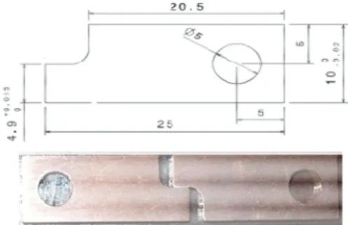
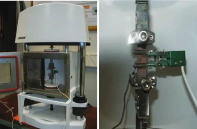
Cyclic displacement controlled tests are performed at 25°C, 200°C and 300°C under various displacement rates 10-2, 10-3 and 10-4mm/s. Creep tests are also achieved at 25°C, 200°C and 300°C with imposed Load of 100 N and 200 N. The shear specimen considered consists of two soldered copper plates with a thickness of 3 mm as shown in figure 1. The plates are soldered using Au-Ge preform whose dimensions are 3×2×0.2 mm. The specimen was obtained using a reflow process of the Au-Ge solder in alternated nitrogen-vacuum atmosphere to improve wet-ting quality and prevent oxidation. This specimen is then mounted on an Electroforce® machine test as shown in figure 2, which is rated up to 450 N and can perform pre-cision materials tests including tension/compression load-ing, fatigue and dynamic material characterization.
Figure 2 Test machine (left) and specimen mounting
(right)
The apparatus is equipped with a furnace which can reach temperatures up to 300°C. Displacements are measured by mean of an axial extensometer as shown in figure 2.
2.2
Thermoviscoplastic modelling of the
solder
At extreme temperature i.e. 300°C, Au-Ge solder exhibit high strain rate sensitivity due to the activated creep mechanisms in the materials. The solder is also subjected to thermal stressing due to the thermal expansions of the underlying materials especially in case of DBC copper plates. The interaction of plasticity and creep leads to the use of unified viscoplastic models which not separate the two phenomena and considers that they are issued from the same time-dependent deformation [6]. So, inspite of the formulation complexity of these models, they can accu-rately reproduce a realistic behaviour of the material under complex loading conditions. In this framework, a McDow-ell’s unified thermoviscoplastic model [7] is used for the modelling task.
2.2.1 Formulation of the model
McDowell’s viscoplastic model contains a set of constitu-tive equations: (1) a flow law which represents the material deformation and the viscosity effects and (2) the evolution equations which describe the associated physical micro-structural aspects using a set of state variables. In this case,
ij
α
represents the kinematic hardening variable and R isthe isotropic hardening variable. The flow law or the evo-lution of the inelastic strain rate is expressed as follows
(
)
(
)
23
, ,
2
ij ij in ij ij ijs
A F
D
J
α
ε
ς
η
σ
α
−
=
Θ
−
(1)As we can see, the flow law depends on a diffusivity pa-rameter and a Zener-Hollowman function F whose ex-pression is fixed generally within the stress and tempera-ture levels [8]. McDowell proposed an exponential term to take into account viscosity effects
(
1)
exp N N F =ς
Bς
+ (2) Where(
)
(
)
2 1 ij ij J R Dσ
α
ς
η
− − = − (3)The factor
η
represents the sensibility partition of the strain rate and mainly varies between 0 and 1. D is an iso-tropic resistance which is usually constant for solder al-loys or proportional to the yield stress for copper(
D=A0R)
. N is a temperature-dependent parameter. A andA are temperature-independent material parameters. 0 The diffusivity parameter depends on the temperature level exp for 2 2 exp ln 1 for 2 2 m m m m T Q T kT T T Q T kT T ! " Θ = − ≥ # $ % & ' # ( ! " ) ! " # Θ = $$− ( $ %+ *%% ≤ # + & ' , & ' + (4) mT is the melting temperature
,
Q is the activation energy, and k is the Boltzmann’s constant. . is defined asg
g =
ifg
≥
0
elseg
=
0
.
Microstructural changes such as dislocation motion, inter-action between dislocations and isotropic defects reparti-tion are described by two variables which are R and !ij
Kinematic hardening variable !ijis divided into two other
variables
α
ijsandα
ij*taking into account the displacement rate of disclocations. In the isothermal case, we can writes in s in s s ij Cb ij C ij ij Cb ij α = ε − α ε − Ω Θα (5) * * in * * * ij H ij H ij
α
=ε
− Ω Θα
(6) In the other hand, a variable constitute a coupling vari-able between isotropic and kinematic hardening effects i.e. the contribution of Riso and biso following
(
−
ω
)
χ
=
1
2
3
isoR
(7)χ
ω
=
isob
(8)
(
)
' in ij χ χ=µ χ−χ ε −µχΩ Θ (9)The variable saturates to χ and its evolution equation includes dynamic and static thermal recovery terms such as those of
α
ijsandα
ij*C, H*, b0, R0, "' and#are temperature-dependent parame-ters.
The thermal static recovery terms are expressed in the fol-lowing forms:
(
)
Ms/2 s s s s ij ij C α α Ω =,
(10)(
)
*/2 * * * * M ij ij C α α Ω =,
(11)(
ij ij)
M /2 C χ χ χ α αχ χ Ω = (12)The yield stress R and the kinematic hardening saturation
b are written respectively as
R
=
R
0( )
T
+
R
isoand( )
T
b
isob
0
R
is the initial yield stress.
*H
,
C
s,
sM
,
C
*,
M
*,
C
χand M are material parameters.χ
2.2.2 Integration and implementation of the
constitutive equations
As for the most popular unified viscoplastic models, McDowell’s model is formulated using a set of strongly coupled, first order differential equations which is hard to solve without advanced integration schemes. McDowell used a semi-implicit integration scheme combined with a Newton-Raphson iteration procedure [9] to solve the model equations. In the semi-implicit scheme, the effec-tive cumulated inelastic strain increment p is updated in implicit way contrarily to the stress and the other state va-riables. Moreover, an automatic stepping procedure is in-troduced in order to improve the solution computation. Let’s see that all the equations of the model may be writ-ten in the formyij = f y t
(
ij,)
. So, the incremental solu-tion of each variable is written as
t dt t t t
ij ij ij ij t
y
+=
y
+ ∆
y
=
y
+ ∆
ty
(13) The aim is to minimize the error function F expressed as
(
, ,
)
( )
ijin t dt:
( )
ijin t dtF
σ α
R
= ∆ − ∆
p
t
ε
+ε
+ (14) Where( )
t dt in ijε
+ depends on the stress and state variableswhich are updated at t + t.
The value of! p is updated for the next iteration k +1 only when the quantity
1 1 k k k
p
p
p
+ +∆
− ∆
∆
is greater than a giventolerance
ε
tolfixed to 10-4 in our case. The update of p isthen computed using the following equation
(
)
(
)
1,
,
,
'
,
,
,
ij ij k k ij ijF
p
R
p
p
F
p
R
σ α
σ α
+∆
∆
= ∆
−
∆
(15)Otherwise, p is retained for the next step as well as the corresponding stress and state variables for the iteration k+1. Algorithm developments as well as the tangent ten-sor computation are detailed elsewhere [9]. Once inte-grated, the McDowell’s model is implemented as subrou-tine UMAT in the finite element code ABAQUS. The solver used in the finite element computation is an asym-metric one with a full Newton-Raphson iteration scheme.
2.2.3 Material parameters identification
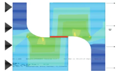
An identification algorithm was performed using Python scripting based on the Least Square minimization proce-dure. This algorithm was combined to UMAT subroutine to identify the model parameters with respect to the finite element model showed on the figure 3.
Copper plates are considered as an elastoplastic material modeled with a combined hardening elastoplastic Cha-boche model. Elastic modulus and Poisson ratio of Au-Ge are taken respectively as E (MPa) = 70495 - 51.9 T (°C) and v = 0.32.
For the finite element modeling, we consider the follow-ing geometry in figure 3 as the used model for the para-meters identification and results extraction
Figure 3 Finite element model for the identification
pro-cedure
McDowell model contains only six temperature-dependent coefficients i.e. E, v, C, H*, b0, R0, !' and
"
. All the temperature dependent parameters may be ex-pressed as functions of temperature as for the Young’s modulus E.The identified material parameters of the Au-Ge solder alloy are given in the table 1 for McDowell’s model
Table 1 Optimized model parameters for Au-Ge solder
For the rate sensitivity viewpoint, and following experi-mental data shown in figure 4 and 5, the material appears to be unaffected by displacement rate variation and shows no sensitivity to loading rate at ambient temperature and 200°C. The material reaches in all cases a load value of approximately 200N for a fixed displacement level at about 0.02 mm.
Following the results presented in figures 6, 7 and 8, for the uniaxial shear tests, the soldered assembly shows a cyclic hardening at least for the first cycle of loading. Al-so, Bauschinger effect is apparent which indicates kine-matic hardening domination.
McDowell’s Model parameters
Temperature 25°C 200°C 300°C n 3.1 - - A 5000 - - B 0.002 - - C 1744 1626 955 D(MPa) 3.2 - - H*(MPa) 125 161 177 w 1 - - Cs 0.0 - - C*(MPa/s) 150 - - Ms 1 - - M* 1 - - Q(J/mol) 48000 - - R0(MPa) 15 10.5 9.6 b0(MPa) 16.9 11.3 10.9
χ
250 121 86 !' 17.3 20.7 20.7Figure 4 Uniaxial shear tests at various temperatures and
strain rates
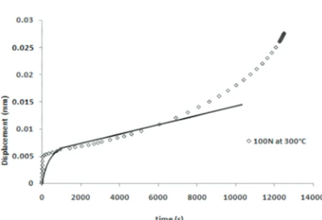
Figure 5 Creep tests at various temperatures and Loads
Good correlation is also recorded between experimental data and numerical simulations obtained by finite element computations especially for the cyclic shear tests which indicate acceptable set of identified model parameters. The modeling task may be extended using thermome-chanical fatigue and ratcheting tests to improve numerical and identification results. A damage model is also suitable for lifetime estimation of the solder material.
Figure 6 Creep tests at 200°C and 100 N
Figure 7 Creep tests at 300°C and 100 N
Figure 8 Cyclic shear tests at 25°C and 10-3 mm/s
3
Conclusion
A set of experimental tests are conducted to characterize the thermoviscoplastic behaviour of Au-Ge solder materi-al. The data is the used to identify the McDowell’s unified viscoplastic model which is successfully implemented in Abaqus using semi-implicit integration algorithm. There was good agreement between numerical results from fi-nite element simulations and tests results. That’s indicates the efficiency of the identified model and thus it will be useful for more complex cases of loading.
4
Literature
[1] Bai, J.G. ; Yin, J. ; Zhang, Z. ; Lu, G.Q. and Van Wyk, J.D. : High-Temperature Operation of SiC Power Devices by Low-Temperature Sintered Silver Die-Attachment, IEEE Transcations On Advanced Packaging, Vol. 30, No. 3, August 2007, pp. 506 – 510.
[2] Bai, J.G. ; Calata, J.N. ; and Lu, G.Q. : Processing and Characterization of Nanosilver Pastes for Die-Attaching SiC Devices. IEEE Transcations On Electronics Packa-ging Manufacturing, Vol. 30, No. 4, October 2007, pp. 241 – 245.
[3] Lee, C.C. ; Wang. C.Y.; and Matijasevic, G. : Au-In Bonding Below the Eutectic Temperature. IEEE Transca-tions On Components, Hybrids, And Manufacturing Technology, Vol. 16, No. 3, May 1993, pp. 311 – 316. [4] Wang P.J., Kim J.S. and Lee C.C., A.: A New Bon-ding Technology Dealing with Large CTE Mismatch Between Large Si Chips and Cu Substrates. Electronic Components and Technology Conference 2008, pp. 1562 – 1568.
[5] Tjong, S.C. ; Ho, H.P. and Lee, S.T. : The interdiffu-sion of Sn from AuSn solder with the barrier metal depos-ited on diamond, Materials Research Bulletin, Vol. 36 , May 2001, pp. 153–160
[6] Krausz, A. S. ; Krausz, K. : Unified constitutive laws of plastic deformation. Elsevier 1996.
[7] McDowell, D.L.: A Nonlinear kinematic hardening theory for cyclic thermoplasticity and cyclic thermovis-coplasticity, International Journal of Plasticity, Vol. 8, 1992, pp. 695-728.
[8] Stouffer, D.C. and Dame L.T. : Inelastic Deformation Of Metals: Models, Mechanical properties and metal-lurgy, John Wiley & Sons Inc, 13 février 1996
[9] Fu, C.; McDowell, D.L. and Ume, I.C. : A Finite Ele-ment Procedure of a Cyclic Thermoviscoplasticity Model for Solder and Copper Interconnects, Transactions of the ASME, Vol 120, 1998, pp. 24 – 34.