HAL Id: hal-01171130
https://hal-mines-albi.archives-ouvertes.fr/hal-01171130
Submitted on 3 Jul 2015
HAL is a multi-disciplinary open access
archive for the deposit and dissemination of sci-entific research documents, whether they are pub-lished or not. The documents may come from
L’archive ouverte pluridisciplinaire HAL, est destinée au dépôt et à la diffusion de documents scientifiques de niveau recherche, publiés ou non, émanant des établissements d’enseignement et de
An innovative hand-held vision-based digitizing system
for 3D modelling
Benjamin Coudrin, Michel Devy, Jean-José Orteu, Ludovic Brèthes
To cite this version:
Benjamin Coudrin, Michel Devy, Jean-José Orteu, Ludovic Brèthes. An innovative hand-held vision-based digitizing system for 3D modelling. Optics and Lasers in Engineering, Elsevier, 2011, 49 (9-10), pp.1168-1176. �10.1016/j.optlaseng.2011.05.004�. �hal-01171130�
An innovative hand-held vision-based digitizing system
for 3D modelling
Benjamin Coudrina,b,c,d,∗, Michel Devyb,c, Jean-Jos´e Orteud, Ludovic Br`ethesa
a
NOOMEO ; rue Galil´ee, BP 57267, 31672 Lab`ege CEDEX, France
b
CNRS ; LAAS ; 7 avenue du colonel Roche, F-31077 Toulouse Cedex 4, France
c
Universit´e de Toulouse ; UPS, INSA, INP, ISAE ; UT1, UTM, LAAS ; F-31077 Toulouse Cedex 4, France
d
Universit´e de Toulouse ; Mines Albi ; Institut Cl´ement Ader (ICA) ; Campus Jarlard, F-81013 Albi, France
Abstract
We describe a new hand-held 3D modelling device using vision and inertial measurements. Our system allows fast and accurate acquisition of the ge-ometry and appearance information of any 3D object. We focused our work towards an easy manipulation and operating condition.
Our methods allow automatic registration with no preparation of the scene (i.e. no markers) even when the object is moved between two acquisi-tions.
In this paper, the design of the system and the developed methods for its use are presented. The system has been evaluated, qualitatively and quan-titatively, using reference measurements provided by commercial scanning devices. The results show that this new hand-held scanning device is really
∗Tel : (+33)5.61.00.77.18 ; Fax : (+33)9.74.76.02.52
Email addresses: [email protected] (Benjamin Coudrin),
[email protected](Michel Devy), [email protected] (Jean-Jos´e Orteu), [email protected] (Ludovic Br`ethes)
*Manuscript
competitive for modelling any 3D object.
Keywords: 3D digitizing; 3D modelling; hand-held; registration
1. Introduction
1
3D Object Modelling has generated many research works in the last
2
decades, especially for Non Destructive Testing or Quality Control
appli-3
cations. Several systems can be found off-the-shelf, either based on vision [1]
4
or on laser ranging [2]. New applications where 3D modelling must be
per-5
formed by non expert people are arising, for instance for archeologists,
cu-6
rators or artists who want to model art objects. Moreover, several potential
7
mass market applications are emerging, e.g. 3D modelling from smart devices
8
either embedded on assistance robots or moved by hand around an object.
9
These new applications involve several constraints. In particular, the 3D
10
modelling task is often executed in a human environment, typically at home,
11
where it is better to avoid laser-based technologies. Moreover the system
12
must be user-friendly, lightweight to be hand-held (i.e. compact), operated
13
with a minimal preparation of the environment (i.e. no marker), and cheaper
14
than existing systems. In that context, Vision, generally associated with
15
illuminators [3, 4], is the better way to acquire sensory data. Some hand-held
16
systems exist in the industrial community. Mostly these systems require to
17
place a reference in the scene. Some use magnetic references or photometric
18
targets. This leads to a more complex digitization process and can forbid to
19
move the object during the process.
20
This paper presents a new Vision-based hand-held 3D scanner allowing
21
acquisition of geometry and texture from an object without any scene
ration. The object is first represented by clouds of 3D points and then with a
23
textured mesh. Digitizing 3D objects requires a sequential process of
geomet-24
ric modelling from visual data acquired from camera(s) moved by a robot or
25
by an operator around the object. 3D reconstruction gives a 3D point cloud
26
from each acquisition. Clouds of 3D points are fragmented representations of
27
space that need to be merged. This imposes to know the shooting positions
28
of the scanner. Our scanner being hand-held, we have no a priori model for
29
this motion, like we would have if the scanner was held by a robot or if we
30
had placed targets in the scene.
31
Several 3D registration algorithms have been proposed since a long time
32
in order to merge 3D data obtained from several viewpoints. Besl et al.
33
introduced the main method used to estimate the rigid transformation
be-34
tween two clouds of 3D points, the so-called ICP algorithm (Iterative Closest
35
Point) [5]. This method has since been adapted with numerous variations [6]
36
in order to speed up the convergence and decrease the complexity. Sandhu
37
et al. [7] recently combine ICP with a particular filtering approach. Li
38
et al. [8] improved the robustness, providing a guaranteed registration. Our
39
registration method combines several operations, based on IMU (Inertial
Mo-40
tion Unit) measurements, ICP-based algorithms and visual odometry from
41
tracked interest image-points.
42
The aim of this new 3D modelling system is to provide an easy to use
43
device. This means that we focused our work on providing reliable and mostly
44
automatic operation. Being hand-held, and lightweight, the device is easily
45
moved and can access a large range of view points, allowing to scan complex
46
shape objects in details or in difficult access conditions. Since no preparation
is required, the overall modelling process has been made shorter and the skill
48
level required for the operator has been reduced. Moreover, the system only
49
requires to be plugged to a computer, which allows to use it with a laptop
50
in outdoor scanning tasks for example.
51
Next section is devoted to the sensor description. Then section 3 presents
52
the main modelling steps: image acquisition, 3D reconstruction and 3D
reg-53
istration. In section 4, several models built from our approach are evaluated,
54
from comparisons either with the actual models for known objects, or with
55
models built with commercial scanning systems. Finally, section 5 presents
56
some outlooks for our future works.
57
2. Description of the system
58
This new vision-based digitizing system is principally composed of two
59
cameras used as a stereovision pair. 3D data is obtained by triangulating
60
image points between a pair of images. Matching pixels in areas of
homo-61
geneous intensity in images is impossible. To tackle this problem, we use a
62
projection of a speckle pattern to give the observed scene a suitable random
63
texture.
64
At a given instant, the system can only acquire a partial view of the scene
65
due to the field of view of the cameras. Modelling a scene from a hand-held
66
vision-based system requires to aggregate these partial views acquired at
67
several instants. This is the problem of estimating the pose or the motion of
68
the digitizing system throughout time. To help us in this task, the digitizing
69
system has been equipped with an inertial motion unit (IMU) able to measure
70
the dynamic or the attitude of the digitizing system.
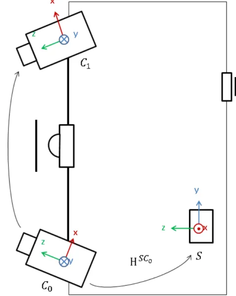
The system weights 1.8 kg, its dimensions are 220 × 240 × 90 mm. Figure
72
1 describes our system and the frames associated with the sensors.
73
[Figure 1 about here.]
74
2.1. Cameras
75
The digitizing system is mainly built around two cameras. The cameras
76
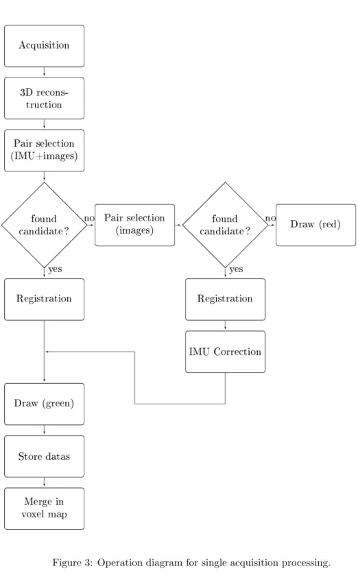
are equipped with a global shutter CCD sensors with a 1024 ×768 resolution.
77
They can operate up to a 39 Hz maximum frame rate. However, using a frame
78
rate close to the maximum decreases image quality.
79
The first camera, placed at the bottom of the system, is called the coaxial
80
camera because it shares its frame with the absolute frame chosen for the
81
system. The coaxial frame is noted C0.
82
The second camera, placed at the top of the system, is the lateral camera.
83
Its frame is noted C1. We suppose that the transformation between the lateral
84
and the coaxial frames is known1 and noted HC1C0
, such that : 85 pC1 1 = H C1C0 pC0 1 = R t 0 1 pC0 1 (1)
where R and t are respectively the rotation matrix and translation vector
86
relating the coaxial frame and the lateral frame.
87
It should be noted that, to guarantee the best precision in matching and
88
to avoid noise, the cameras need to be perfectly synchronized during the
89
image acquisition. This is achieved by using a hardware trigger signal.
90
1The stereo-vision system has been calibrated using a chessboard calibration target,
fol-lowing the method described in [9]. The chessboard has been modified to allow automatic initialization.
2.2. Inertial Motion Unit
91
The IMU is composed of three accelerometers, three gyrometers and three
92
magnetometers. It can operate up to approximately 120 Hz and gives
infor-93
mation about the dynamics of our hand-held system :
94
• acceleration a = [ax ay az]T
95
• angular rate ω = [ωx ωy ωz]T
96
• surrounding magnetic field direction b = [bx by bz]T
97
The integration of acceleration and angular rate measurements can give
98
static information – position, attitude – to a certain extent. Indeed, due to
99
important noise level and biases, position and attitude can drift quickly. It is
100
yet possible to compose all the dynamics measurements to obtain a relatively
101
accurate estimation of the attitude of the IMU using a Kalman filter [10, 11].
102
Magnetic field is static and consequently its measurement does not drift
103
incrementally. Accelerometers measure all accelerations applied to them,
in-104
cluding gravity acceleration. Thus, we are able to express current
measure-105
ments gkand lk– respectively current gravity acceleration vector and current
106
magnetic field direction – with respect to the current estimated attitude.
107
gk = R (ek) g0 (2) lk = R (ek) l0 (3)
where g0 = [0 0 g]T is the gravity acceleration vector expressed in world
108
frame, l0 is the measurement of the magnetic field when the inertial sensor
is aligned with world frame, ek is the current attitude expressed in Euler
110
angles, and R (e) is the rotation matrix composed from euler angles vector
111
e.
112
Angular rate measurements ωkare combined at the prediction step of the
113
Kalman Filter by integration at high rate. Indeed, locally the estimation
114
does not drift much and the system is considered linear.
115
˙ek = ωk (4)
Inertial motion unit frame is noted S. Transformation between the coaxial
116
frame C0 and the inertial frame is noted HS C0 :
117 pS 1 = H S C0 pC0 1 = RS C0 tS C0 0 1 pC0 1 (5)
with RS C0 and tS C0 being, respectively, the rotation matrix and transla-118
tion vector of the frame change. This transformation is calibrated by
com-119
paring attitude measurements and camera poses from the observation of a
120
known chessboard target. The problem to be solved is then similar to a
121
Hand-Eye calibration [12].
122
2.3. Light pattern
123
The aim of the system is to allow 3D digitizing in the widest possible
124
conditions. Consequently we focused on mechanisms to gain independence
125
to environmental disturbances, lighting being the most important. This is
126
the reason why the system is equipped with a pattern projector to texture
127
the scene and facilitate the matching process between images. This projector
is a LED matrix coupled with a slide image. This slide is a speckle pattern
129
printed on a glass tile.
130
Moreover, LED rings are added to each camera to be used as secondary
131
light sources in low-lighted environments.
132
Since our system is vision-based, some conditions may still be limitating.
133
Specular reflections will not allow good 3D reconstruction for example. The
134
system tries to adapt its exposure parameters to avoid saturation on images
135
but in the case of intense or large specular reflections, since the system is
136
blinded by light, it will fail to find a good exposure time, and will fail to
137
measure properly. This happens when one scans a specular surface with a
138
frontal point of view : all the light from the projector is reflected towards
139
the system. In this case, the best solution is to scan with a less frontal point
140
of view to direct the reflection away from the cameras. Moreover, since we
141
merge several scans acquired from multiple points of view, a hole created by
142
a specular reflection in an acquisition is filled by the modelling from another
143
acquisition without specular reflection.
144
3. Operationg conditions
145
In the sequel, strategies and operating modes for 3D modelling using our
146
particular system design are described. An overview is provided and some
147
details about the main methods are given.
148
3.1. Description
149
Our digitizing system is an incremental modelling device. The
construc-150
tion of the 3D model is done incrementaly using several raw data acquired
151
sequentially.
The aim of our project was to design the system as simply as possible.
153
The user controls the digitizing system using a trigger. A single pression on
154
it switches on the device. Prior to doing anything, when starting, the
sys-155
tem launches a sequence for calibration of exposure time and light intensity
156
parameters to fit the environment. This step lasts a couple of seconds.
157
The system is then operational and runs in a preview mode. Three
oper-158
ating modes are available. Figure 2 shows how actions on the trigger drive
159
transitions between each operating mode.
160
[Figure 2 about here.]
161
The starting state is when the digitizing system is off. As we stated above,
162
a short pression on the trigger powers the device on to enter a preview state.
163
In this operating mode, raw data are acquired, processed and displayed,
164
and then erased. Pressing the trigger for a longer time allows the actual
165
modelling, that is to say raw data are still acquired and processed but also
166
stored and results of the processing are merged to the results of previous
167
acquisitions.
168
The methods used for incremental modelling were chosen in order to
169
facilitate the overall process. A common difficulty in modelling systems is,
170
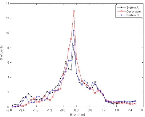
for instance, the acquisition of the support side of an object. The object
171
is placed on a table and the support side is not visible unless the object is
172
moved. Most of existing systems require to digitize this side separately and
173
merge it manually during post-processing. The pipeline we propose (Figure
174
3) is designed to allow a fully automatic modelling during acquisition.
175
[Figure 3 about here.]
Our methods rely on the use of image processing algorithms and inertial
177
sensing. The main drawback of most methods combining vision and inertial
178
data is that all the processing is based on a fixed global frame. Moving
179
the object is then not possible because it would mean changing the absolute
180
reference. Our pipeline is designed to detect and correct these displacements.
181
For each acquisition time, the digitizing system acquires sequentially, at
182
high rate, two pairs of images – one with the projected pattern, one with no
183
projection – and two attitude estimations synchronised with each pair. A 3D
184
point cloud is created, expressed in the coaxial camera frame. Incremental
185
modelling requires to find the transformation between this camera frame
186
and the global frame of the current model already created. Using attitude
187
measurements and images, a best candidate for alignment process can be
188
quickly chosen. After the alignment step, the 3D points can be merged in
189
a voxel-map-based structure. This is used mainly for visualization, allowing
190
fast and simple sampling of geometric information. Raw data are stored to
191
be used in post-process refinements.
192
If the object has been moved or if the overlap of the current view with
193
the current model is insufficient, no good candidate for registration is found.
194
In this case, a second best candidate search method is used. Of course, if
195
the overlap is too small, this method will fail and the user will be notified.
196
If the object has moved, the inertial measurements become inconsistent with
197
the model frame. To align the inertial frame to the new world frame, a
198
correction transformation related to the object motion has to be estimated.
199
The second method used is based on image indexation to retrieve a good
200
registration candidate from an interest points base. This method is slower
than combination of vision and inertial data but is not dependent on a global
202
reference. When a correspondant is found, the registration process gives us
203
the actual transformation between the coaxial camera frame and the current
204
model, allowing us to apply a correction to the attitude estimation from the
205
inertial sensor.
206
When an acquisition is resumed after an interruption, the system checks
207
if the object has moved. Matching is performed using inertial sensing and
208
image detection. If no consistent pose can be found with this method, then
209
the system suggests that the object has moved and the inertial measurement
210
is not usable. The image-only method is then applied.
211
With such a pipeline, the acquisition process is made more user-friendly.
212
Indeed, the modelling can be stopped and resumed easily, and the entire
ob-213
ject can be scanned in the same automatic process by pausing the acquisition,
214
moving the object, and resuming the operations.
215
3.2. 3D generation
216
Matching points between stereo images allows an inverse projection to
217
retrieve 3D information from each pair of points. It is the so-called
trian-218
gulation process [13]. When the matching of points or camera parameters
219
are not perfect, optical rays linking camera centers to these points does not
220
intersect. Optimisation or selection heuristic need to be chosen.
221
Considering epipolar geometry, a point in an image and each point on
222
the corresponding epipolar line in the other image are coplanars with optical
223
centers of the cameras. Using stereo rectification [14, 15], matching points
224
lie on the same row in rectified image space, so the intersection between two
225
optical rays always exists. Moreover, epipolar geometry reduces the search
space for stereo correspondent to a line of points.
227
Matching is then a two step process : coarse dense pairing, and
refine-228
ment. First step is a global process, trying to match all pixels in an image.
229
The search space in the other image is discretized – to 1 pixel for instance
230
– and is consequently imprecise. This process uses the projected pattern to
231
identify corresponding points without ambiguity.
232
Increasing the search space to be continuous allows the refinement of
233
coarse pairs. Moreover, fine correlation techniques [16] optimize a
transfor-234
mation of the matching pattern to approximate the projective distortion.
235
3.3. Registration
236
The online registration process is divided into two main actions :
237
• finding the best previous view for a pairwise alignment
238
• estimating the transformation for the best fit of both views
239
These methods are only described briefly here and will be discussed more
240
precisely in a forthcoming paper.
241
Finding the best candidate for a pairwise alignment in real time needs,
242
in a way or another, a kind of mapping or classification process. It consists
243
in finding a previously acquired view that maximizes a proximity criterion.
244
In our approach, we use the inertial sensing in first intent to fastly find a
245
candidate in the rotation space. The rotation shift between the two views is
246
then immediatly available. The translation part is found by matching interest
247
points between images. A score is used to decide whether the candidate is
248
good enough or not.
It should be noted that 3D data is obtained thanks to the projection of
250
a speckle-pattern onto the scene that is moving with our digitizing system.
251
Matching interest points between images [17] with a moving pattern
projec-252
tion is impossible. This is the reason why each acquisition is composed of a
253
pair of images with projection and a pair without projection. Image points
254
can be matched in images without illumination between two acquisition
in-255
stant n and n + 1, allowing to compute pose transformation. It is obvious
256
then that, due to the hand motion, the pose is not exactly the same when
257
acquiring images with projection – from which 3D points are generated –
258
and when acquiring images without projection – from which pose estimation
259
can be found. This introduces an imprecision, acceptable to have a good
260
initial approach, but not accurate enough for an acceptable alignment. A
261
fast registration method – a few iterations of ICP [18, 5] – needs to be run
262
to finish the process.
263
If the search in rotation space gives no result or a result where matching
264
does not pass the score test, then the inertial sensing may have been biased
265
by the motion of the object. The rotation measurement is then forgotten
266
and the candidate is chosen by image indexation, trying to find a previous
267
acquision whose image interest points match well with those of the current
268
acquisition. This process is not as fast as the first one, which is acceptable
269
for ponctual events like moving the object, but would lead to an important
270
loss in acquisition frequency if used in first intent.
271
In the latter approach, the fast final registration gives an absolute rotation
272
shift between the previous – known – acquisition and the current – biased
273
– one. This shift is used as a corrector for next acquisitions, giving the
possibility to use the inertial method again.
275
3.4. Finalization
276
The model constructed incrementaly in real time is still quite imprecise
277
and can be noisy. To finalize the process, this model needs to be refined and
278
cleaned. This means that the poses and computed 3D points are reestimated
279
together in a kind of bundle adjustment process.
280
The representation of the model is important regarding to the target
ap-281
plication. Meshing is required most of the time. Higher level of representation
282
like surfacing can be needed or other informations like surface texturing.
283
4. Evaluations
284
This section aims at showing the potentialities of the scanner within two
285
applications, a qualitative one and a more quantitative one, comparing results
286
to some reference scanning systems of the community.
287
4.1. Experimental protocol
288
For our evaluations we scanned several objects with three systems : our
289
hand-held digitizing system and two commercial scanning devices widely used
290
in the community, which will be called A and B in the sequel. The two
291
commercial devices are fixed scanning devices using optical technology for
292
3D reconstruction. These systems are not clearly identified because, being
293
system designers ourselves, we don’t want to bias the purpose of this article
294
to a commercial discussion.
In the evaluations we used the Geomagic Qualify v12 software for
com-296
parisons between scans and CAD surfaces. The system A does not provide
297
a registration solution so we used Geomagic Studio v12 to align the scans.
298
Scanner A is a fixed device, using laser triangulation for 3D measurement.
299
It is an heavy system not easy to handle. System B is also a fixed device,
300
lighter than system A. It uses fringe projection for 3D measurement and is
301
coupled to a photogrammetry system for localization, requiring that several
302
targets be placed in the scene.
303
Both systems have switchable optics for focal length modification.
304
Operating conditions and specifications of both scanners A and B are not
305
really comparable to our scanner. However they have been chosen for the
306
announced accuracy and because they are widely used in scientific and
indus-307
trial communities. Technical informations about these devices are provided
308
in table 1.
309
[Table 1 about here.]
310
4.2. Cylindrical Gauge Block
311
To get a more defined idea of the relative accuracy of the systems, we
312
started with scanning a cylindrical gauge block used for micrometer
calibra-313
tion. The inner diameter of the cylinder is known (70.004 mm) with an
314
accuracy of 1 µm.
315
Evaluation is done using a single acquisition. For each evaluation, the 3D
316
point cloud is registered to a theoretical surface of a 70.004 mm diameter
317
1Needs to change the focal length to cover all the distances. 2To the Z reference plane.
cylinder using Geomagic Qualify. Points are projected orthogonaly on the
318
surface and the projection distance – the error – is measured. The analyses
319
are based on the mean and standard deviation of the error distances.
320
Table 2 shows the results of this test.
321
[Table 2 about here.]
322
This first test was not intended to make a comparison and ranking of the
323
scanners but to be used as a basis for the evaluation. It tends to give us an
324
absolute reference of the 3D reconstruction process for each device. One can
325
note that our device is in the same accuracy range than system A whereas
326
system B provides more accurate results.
327
4.3. Statue
328
The first evaluation consists in scanning a statue shown in Figure 4.
329
This object is composed of large smooth parts (face, support side, . . . ) and
330
complex shape areas (cloak mostly).
331
[Figure 4 about here.]
332
At the beginning of the process, the statue is disposed on its support
333
side. We began the acquisition with the face, and then moving to our left.
334
The object has been turned around the vertical axis several times during
335
the process to acquire the cylinder of the head. After a complete turn, we
336
scanned the top of the head. Then the object has been moved to be placed
337
face up. By scanning from the bottom of the face we acquired the support
338
base, which has been completed by placing the object face down and doing
339
the same from the back of the head to the support side.
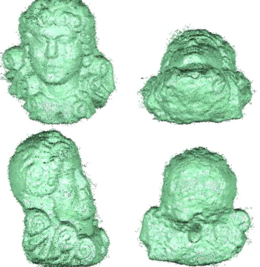
The result of the scan is shown in Figure 5.
341
[Figure 5 about here.]
342
The model is noisy but already recognizable. It still needs to be finalized.
343
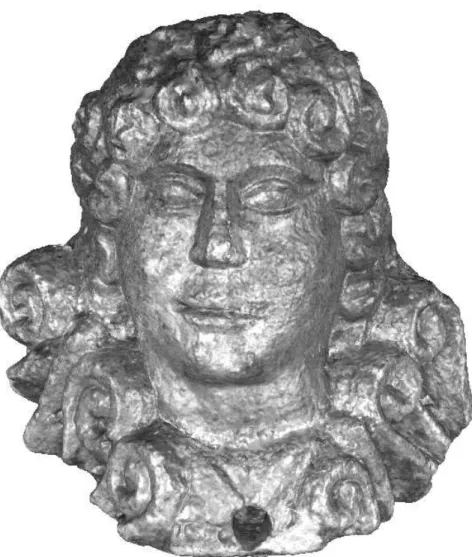
We refined the model, cleaned outliers and then meshed. The final result is
344
shown in Figure 6. The texture provided by the images has also been applied
345
to the final model.
346
[Figure 6 about here.]
347
The operation of our device allows us an easy handling which is of great
348
interest in this type of object. The statue has been scanned using the
com-349
mercial scanning devices but handling fixed systems adds difficulties when
350
scanning slighltly hidden details like those on the cloak. Figure 7 illustrates
351
a detail of the cloak which suffers information loss in a scan from one of the
352
commercial devices.
353
[Figure 7 about here.]
354
4.4. Mechanical test piece
355
For a more quantitative analysis, we used a stamped sheet metal part.
356
To avoid specular effect, the object was mattified.
357
The object is scanned only in its upper face. The sheet being thin, the
358
interest of scanning the opposite face and the sides is questionable considering
359
the resolution and the accuracy of most scanners.
360
[Figure 8 about here.]
4.4.1. Comparison of the three scans with the CAD model
362
In our test benchmark, we first compared our scan and the scans
pro-363
vided by systems A and B with the CAD model. Due to mechanical efforts,
364
particularly on release of blank holders, the object has been deformed and it
365
does not correspond anymore to its theoretical CAD model. We registered
366
our test scans to the CAD reference along a same interest zone, favouring
367
the central stamping, supposed to be less deformed. Results are shown in
368
Figure 9.
369
[Figure 9 about here.]
370
The metric used is based on a direct orthogonal distance from scanned
371
points to the reference surface. Figure 10 provides the error distributions for
372
each scan.
373
[Figure 10 about here.]
374
This test allows us to check if there is a bias between several
measure-375
ments of the same object. Comparing the results, our first observation is
376
the similarity of the error maps. With this test, we can see also that the
377
comparison method is stable. Similar data leads to similar registration and
378
projection, considering we used a common alignment reference. This allows
379
us to use this comparison method for the next tests.
380
4.4.2. Comparison with scan B
381
The next evaluation focuses on the impact of our finalization step on
382
accuracy. The CAD surface being a bad ground truth we decided to use scan
B provided by the more accurate device – according to the manufacturers’
384
specification and the cylinder test – as a reference.
385
[Figure 11 about here.]
386
Figure 11 compares the 3D shape measured with our digitizing system
387
before the post-processing step and after this finalization. Point clouds are
388
projected onto the reference – from system B – model.
389
In the raw cloud, a lot of noise appears. This noise is an oscillating
phe-390
nomenon from side to side of the mean surface. Large deviation is observable
391
at the extremities of the model. A boundary effect appears, leading to largely
392
biased measurements in these areas.
393
After the finalization step, noise has been largely reduced, at the point
394
that it is not visible with our colour span. Observing the histogram, we
395
can see that deviation caused by the fast registration method used has been
396
largely reduced by using more accurate registration. The model is more
397
largely comparable to scan B. One can note that boudaries effect, if reduced,
398
still appears.
399
Summary of errors in both steps is given in Table 3.
400
[Table 3 about here.]
401
5. Conclusion
402
In this article we presented our new hand-held 3D scanning device based
403
on vision technologies. We focused the design of this scanner on an
easy-to-404
use scanner. No equipment or markers need to be put in the scene and, being
405
hand-held, the scanner allows a more dexterous manipulation. The operation
has been made simple, real-time and mostly automatic. A finalization step
407
allows the creation of a more accurate and usable model.
408
We evaluated the performances of our scanner on several test objects to
409
cover more widely the 3D digitizing applications. We based our evaluations
410
on results obtained by scanning the same objects with well known and widely
411
used commercial devices. Our tests tend to prove that the proposed system
412
matches the requirements of common applications in qualitative terms,
accu-413
racy and usability but with an eased operation allowing to fasten the overall
414
modelling process.
415
Our future works will focus on improving the texturing operation and
416
qualifying more precisely the accuracy and performances of our system. We
417
will also focus our work on trying to reduce noise in the digitizing process.
418
Another improvement can be made by considering ROI-based reconstruction
419
[19]. With such an approach, reconstruction can be processed faster and
420
with reduced noise level due to filtering ill-observed zones outside the central
421
object in images.
422
Acknowledgments
423
We thank the IRIT (Institut de Recherche en Informatique de Toulouse)
424
laboratory from Toulouse – France, and the ENIT LGP (Ecole Nationale
425
d’Ing´enieurs de Tarbes – Laboratoire G´enie de Production) laboratory from
426
Tarbes – France, for the help they provided by scanning our test objects with
427
their commercial scanners (scanners A and B in this paper).
References
429
[1] Pan Q. , Reitmayr G. , Drummond T.W. . Interactive model
recon-430
struction with user guidance. In: Mixed and Augmented Reality, IEEE
431
/ ACM International Symposium on. 2009, p. 209–10.
432
[2] Curless B. . From range scans to 3D models. SIGGRAPH Computer
433
Graphics 2000;33(4):38–41.
434
[3] Matabosch C. , Fofi D. , Salvi J. , Batlle E. . Registration of surfaces
435
minimizing error propagation for a one-shot multi-slit hand-held
scan-436
ner. Pattern recognition 2008;41(6):2055–67.
437
[4] Strobl E. , Mair E. , Bodenm¨uller T. , Kielh¨ofer S. , Sepp W. , Suppa
438
M. , et al. The self-referenced DLR 3D-Modeler. In: International
439
Conference on Intelligent Robots and Systems. St. Louis, MO, USA;
440
2009, p. 21–8.
441
[5] Besl P.J. , McKay N.D. . A method for registration of 3-D shapes.
442
IEEE Transactions on Pattern Analysis and Machine Intelligence
443
1992;14(2):239–56.
444
[6] Rusinkiewicz S. , Levoy M. . Efficient variants of the ICP algorithm.
445
In: Third International Conference on 3D Digital Imaging and Modeling
446
(3DIM). 2001,.
447
[7] Sandhu R. , Dambreville S. , Tannenbaum A. . Particle filtering for
regis-448
tration of 2D and 3D point sets with stochastic dynamics. In: IEEE
Con-449
ference on Computer Vision and Pattern Recognition (CVPR). 2008,.
[8] Li H. , Hartley R. . The 3D-3D registration problem revisited. In: IEEE
451
International Conference on Computer Vision. 2007, p. 1–8.
452
[9] Zhang Z. . A flexible new technique for camera calibration. IEEE
Trans-453
actions on Pattern Analysis and Machine Intelligence 2000;22:1330–4.
454
[10] Marins J.L. , Yun X. , Bachmann E.R. , McGhee R.B. , Zyda M.J. .
455
An Extended Kalman Filter for Quaternion-Based Orientation
Estima-456
tion Using MARG Sensors. In: International Conference on Intelligent
457
Robots and Systems. 2001,.
458
[11] Lefferts E.J. , Markley F.L. , Shuster M.D. . Kalman filtering for
space-459
craft attitude estimation. Journal of Guidance, Control and Dynamics
460
1982;5(5):417–29.
461
[12] Park F.C. , Martin B.J. . Robot sensor calibration: solving AX=XB on
462
the euclidean group. IEEE Transactions on Robotics and Automation
463
1994;10(5):717–21.
464
[13] Hartley R.I. , Sturm P. . Triangulation. Computer Vision and Image
465
Understanding 1997;68(2):146–57.
466
[14] Fusiello A. , Trucco E. , Verri A. . A compact algorithm for rectification
467
of stereo pairs. Machine Vision Application 2000;12(1):16–22.
468
[15] Bugarin F. , Henrion D. , Sentenac T. , Lasserre J.B. , Orteu J.J. .
469
Optimisation globale polynomiale appliqu´ee `a la rectification projective
470
d’images non calibr´ees (in french). In: Conf´erence en Reconnaissance
471
des Formes et Intelligence Artificielle. 2010,.
[16] Garcia D. . Mesure de formes et de champs de d´eplacements
tridimen-473
sionnels par st´er´eocorr´elation d’images (in french). Ph.D. thesis; Institut
474
National Polytechnique de Toulouse; 2001.
475
[17] Bay H. , Tuytelaars T. , Van Gool L. . Surf: Speeded up robust features.
476
In: European Conference on Computer Vision. 2006, p. 404–17.
477
[18] Chen Y. , Medioni G. . Object modelling by registration of multiple
478
range images. Image and Vision Computing 1992;10(3):145–55.
479
[19] Li W. , Sch¨utze R. , B¨ohler M. , Boochs F. , Marzani F.S. , Voisin Y.
480
. Preprocessing of region of interest localization based on local surface
481
curvature analysis for three-dimensional reconstruction with
multireso-482
lution. Optical Engineering 2009;48(6).
(a) (b)
Figure 7: Detail of the object. In complex areas of the object, some faces can be hard to observe due to occlusions. (a) Observing complex surfaces with our system is eased by its hand-held operation, allowing a more dexterous manipulation. (b) Scan from system A, with a less dexterous operation information, losses can occur.
Figure 8: Stamped sheet metal part used for our tests and resulting point cloud provided by our system.
(a) (b)
(c)
Figure 9: Comparison of scans with theoretical surface : (a) Scan using system A ; (b) Scan using system B ; (c) Scan using our hand-held scanner.
(a)
(b)
Figure 11: Comparison between our scan and scan B : (a) before finalization ; (b) after finalization.
A B Our system
Motion Fixed Fixed Hand-held
Technique Laser triangulation Structured light Structured light
Registration Manual Photogrammetry Automatic
Weight (kg) 15 7.4 1.8
Dimensions (mm) 221 × 412 × 282 490 × 300 × 170 220 × 240 × 90
Focal length (mm) 14 16 8
Operating distance1 (m) 0.6 – 1.2 0.7 – 2 0.35 – 0.5
Measurement volume (mm) from 111 × 83 × 40 from 135 × 108 × 108 from 10cm
3 to 1m3
to 1196 × 897 × 800 to 1700 × 1360 × 1360 NC
Accuracy (X,Y,Z)2 (mm) ±(0.22, 0.16, 0.10) NC NC
Point spacing (mm) NC 0.08 – 1.0 0.3
Measuring noise (mm) NC 0.002 – 0.02 0.1
Table 1: Systems specifications (Commercial systems specifications are provided according to manufacturers’ data sheets).
A B Our system Mean (mm) −0.00115 0.00003 −0.00115 Std. dev. (mm) 0.02764 0.00508 0.02480 Max. error (mm) 0.10238 0.02162 0.08649 Min. error(mm) −0.09151 −0.02569 −0.09392
Before finalization After finalization Mean error (mm) −0.004 −0.001 Std. dev. (mm) 0.373 0.125