Science Arts & Métiers (SAM)
is an open access repository that collects the work of Arts et Métiers Institute of Technology researchers and makes it freely available over the web where possible.
This is an author-deposited version published in: https://sam.ensam.eu Handle ID: .http://hdl.handle.net/10985/13776
To cite this version :
Emmanuel LIZE, Marc REBILLAT, Nazih MECHBAL, Christian BOLZMACHER - Dual PZT sizing for mode decomposition on a composite anisotropic plate - In: 9th European Workshop on Structural Health Monitoring, Royaume-Uni, 2018-07 - 9th European Workshop on Structural Health Monitoring - 2018
9th European Workshop on Structural Health Monitoring July 10-13, 2018, Manchester, United Kingdom
Dual PZT sizing for mode decomposition on a composite anisotropic
plate
Emmanuel LIZÉ1, Marc RÉBILLAT2, Nazih MECHBAL2, Christian BOLZMACHER1 1 CEA, LIST, Sensorial and Ambient Interfaces Laboratory, 91191 - Gif-sur-Yvette
CEDEX, France
2 Processes and Engineering in Mechanics and Materials Laboratory (PIMM, UMR CNRS 8006, Arts et Métiers ParisTech (ENSAM)),
151, Boulevard de l'Hôpital, Paris, F-75013, France, emmanuel.lize@cea.fr
Abstract
Structural Health Monitoring is a multidisciplinary field whose aim is to monitor damages within structures. Damages are detected by means of features - Damage Index (DI) - obtained by comparing measurements obtained from an unknown state with data obtained from a reference state stored in a baseline. Most DIs are calculated using Lamb wave signals generated and received by surface-mounted piezoceramic transducers (PZT) excited around a predefined central frequency. Usually, only the faster mode (𝑆0) is considered on composite structures. However, the symmetric and antisymmetric Lamb wave modes tend to highlight different kinds of damages and are both interesting for SHM purpose. For example, a delamination in a composite plate attenuates the antisymmetric mode and reflects the symmetric one. Using two concentric PZTs (a disc and a ring defining a dual PZT) allows the decomposition of both mode contributions in the received signal. The current work presents a method based on Lamb Wave dispersion curves able to size the dual PZT and to determine the excitation frequencies to use for SHM application. This approach is based on three main observations: (i) Only the first symmetric and antisymmetric modes S0 and A0 must be generated, (ii) the dual PZT used as actuator and the excitation frequencies of the signal used must guarantee the actuation of S0 and/or A0 modes with wave length small enough to interact with the targeted minimal damage size, and (iii) the dual PZT used as sensor must be sensitive to both S0 and A0 modes on the selected range of excitation frequency. This method is applied for the sizing of dual PZT bounded to a highly anisotropic composite plate (CFRP [0,90]16) with a thickness of 2 mm and a minimal targeted damage size of 20 mm. Optimal dimensions of the PZT disk and ring are found and results of mode decomposition method on the optimal range of excitation frequencies obtained on a finite element model are presented. This simple method provides an efficient way for dual-PZT sizing in a SHM context where both 𝐴0 and 𝑆0 modes are investigated.
1. Introduction
Monitoring in real-time and autonomously the health state of structures is referred to as Structural Health Monitoring (SHM) (1). Damage detection using Lamb waves is one of the most common method for the SHM of aeronautic composite structures. Among all the methods employed to trigger and catch Lamb waves, the use of piezoelectric transducer
(PZT) is one of the cheapest and easiest-to-settle. The common approach is based on the comparison of signals recorded on a “pristine” structure - the baseline - against those obtained on a possibly damaged structure. The resulting signals strongly depends on the structure’s mechanical and geometrical properties as well as environmental conditions. Some solutions have been proposed to compensate for the effect of temperature (2–5) or to extend baseline data to a wider range of environmental conditions (6,7). This drawback of existing methods has also fed the interest for “baseline-free” methods. “Baseline-free” is here an abusive word (see Axiom II in (1)) since data, models, or physical assumptions are always needed to decide whether a structure is damaged or not. This expression thus refers here to methods where a baseline of signals recorded from the pristine condition of the monitored structure is not mandatory for damage detection.
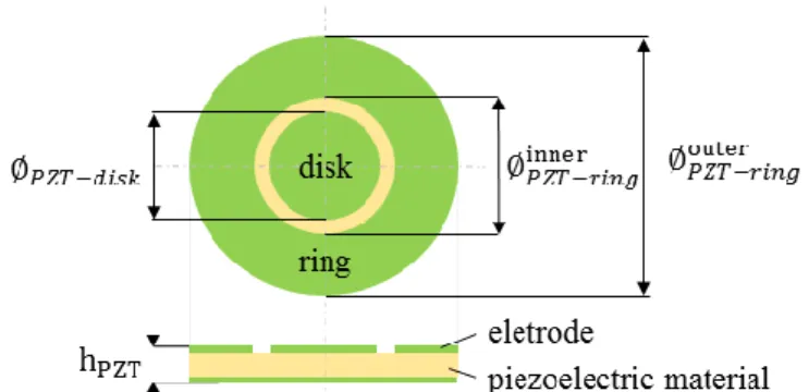
Symmetric and antisymmetric Lamb wave modes are very useful for SHM as they convey complementary information when interacting with damages (8,9). Dual PZTs are made of a concentric ring and disc as shown in Figure 1.
Figure 1 : Simplified view of a dual PZT composed of a concentric ring and a disk.
Both parts can be used as actuator and sensor bringing more signal combinations than conventional PZTs and allow for the isolation of the first antisymmetric 𝐴0 or symmetric 𝑆0 mode (10–14). With dual PZTs, a damage can then be detected in a “baseline-free” manner by using the damage-introduced mode conversion and attenuation of the propagating waves (8). The theoretical aspect justifying the use of those transducers for
“baseline-free” SHM is well developed in (15) and experiments are reported in (16) and
(17). However, the interaction of each mode with the damage is conditioned by the wavelength of the waves generated by the dual PZT. As a consequence, the transducer’s dimensions as well as excitation frequencies must be chosen with care. Previous works with dual PZTs have been carried out on quasi-isotropic structures (12) but no studies have been reported on highly anisotropic structures. In such materials, the amplitude as well as the propagation speed of 𝐴0 and 𝑆0 modes on a path between two PZTs greatly depends on the angle between the path direction and the orientation of the carbon fibers composing the structure (9).
Some of the “baseline-free” methods where mode decomposition based on dual PZT is of interest are here quickly reviewed. The “instantaneous baseline” method is based on a transducer network with paths having the same dimensions and orientations. Instead of comparing signals obtained at a random condition with a pristine baseline, signals are compared instantaneously between paths even under varying environmental conditions (11,18–21). Drawbacks are that examined paths must have identical PZT positioning and bonding and that reflection of elastic waves from boundaries must be avoided. Another technique called the “time reversal” process assumes that for a pristine structure by
sending back the reverse signal received by a given PZT, the input signal used in first place should be recovered. A damage potentially breaks this relation, allowing for its detection. This method has been validated on composite structures (22–26) and its limitations have been identified (27): a high dependence on the excitation frequency, mode dispersion, and reflections from boundaries. In the “reciprocity principle” method, two signals obtained from both possible directions of a given path are directly compared. This method has been used successfully on aluminum (11,16,28) and composite (29) structures. Its drawbacks are that the implemented PZTs must be identically bonded to the structure, and that damages localized far from the investigated path are difficult to detect. In the first part of this article, a method for dual-PZT sizing and excitation frequencies selection according to the targeted application, i.e. “baseline-free” SHM is proposed. Then, based on FEM simulation, the influence of the anisotropy of the material on the mode decomposition method is presented.
2. Dual PZT sizing
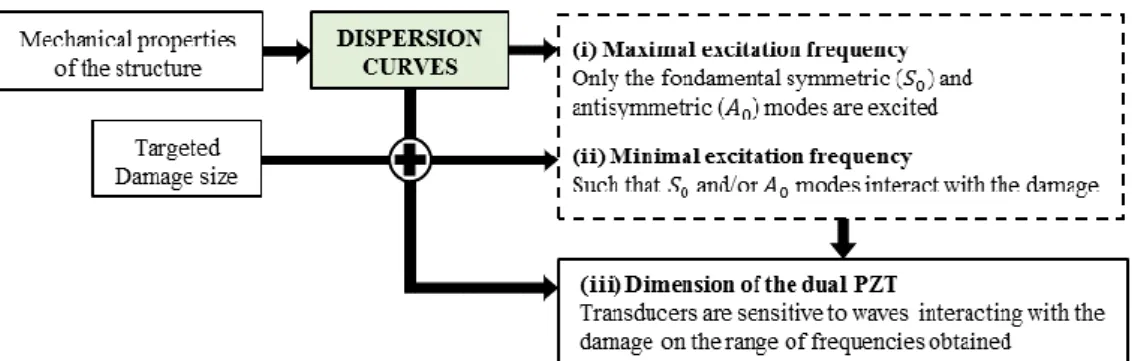
2.1. Generic approachThis chapter presents a generic approach toward the sizing of both parts (ring and disk) of dual PZTs. These dimensions and the excitation frequencies are determined based on the material properties and on the minimal size of the damage to be detected. Three main goals are targeted (see Figure 2): (i) only the first symmetric and antisymmetric modes 𝑆0 and 𝐴0 must be generated, (ii) the dual PZT used as an actuator and the frequencies of the signal used must guarantee the excitation of 𝑆0 and/or 𝐴0 modes with a wavelength small enough to interact with the targeted minimal damage size, and (iii) the dual PZT used as sensor must be sensitive to both 𝑆0 and 𝐴0 modes on the selected range of excitation frequencies.
Figure 2 : Three steps followed in order to select the dual PZT dimensions and the excitation frequency range.
Dispersion curves are computed numerically by finding all the possible frequencies that satisfy Lamb waves dispersion relations with iterations on the wave number 𝑘 (30). For each symmetric and antisymmetric modes, dispersion curves can be displayed as the variation of wavelength 𝜆 = 2𝜋/𝑘 with frequency. Mechanical properties needed are the young modulus 𝐸, poisson ratio 𝜈, density 𝜌 and thickness 𝑡 of the considered structure. Baseline free methods targeted in our work consist in tracking 𝑆0 and 𝐴0 mode conversion and attenuation. It is thus necessary to restrain the domain of applications where only those first two modes propagate. To meet this condition, dispersion curves show that the
excitation frequency should not exceed 𝑓𝑚𝑎𝑥, corresponding to the minimal excitation frequency for which mode 𝐴1 is generated (see Figure 3).
Theoretically half the wavelength 𝜆 of the wave used to detect a damage must be shorter than or equal to the size of the damage ∅𝑑 in order to allow an interaction with it (31):
𝜆
2≤ ∅𝑑 (1)
This statement gives the frequency range on which 𝑆0 and 𝐴0 modes are exploitable: the largest wavelength validating Eq.(1) is 𝜆𝑑 = 2 × ∅𝑑. According to this criterion, the excitation frequency used should be greater than a frequency 𝑓𝐴0 for 𝐴0 mode and 𝑓𝑆0 for
𝑆0 mode, corresponding to excitation frequencies for which wavelength 𝜆𝐴0 and 𝜆 𝑆0 are lower than 𝜆𝑑 (see Figure 3).
The next sizing step consists in ensuring that the dual-PZT element are able to actuate and receive the desired modes at these frequencies, leading to the selection of optimal dimensions for dual PZTs. Two criteria are important in the choice of the PZT according to (32):
as an actuator, the optimal PZT size ∅𝑃𝑍𝑇 is obtained for ∅𝑃𝑍𝑇 = 𝜆 (𝑛 +
1
2) , 𝑛 = 0,1,2, … (2)
as a sensor, the sensitivity of the PZT increases as its size is reduced and the size of the PZT must be inferior to half the wavelength to be detected, i.e.
∅𝑃𝑍𝑇 ≤ 𝜆
2 (3)
When classic circular PZT are used as actuators and sensors, the optimal PZT size is obtained for ∅𝑃𝑍𝑇 = ∅𝑑 by considering criteria described by Eq.(1), (2) and (3). However, this choice limits in practice the application of detection to very few excitation frequencies. An advantage of the dual PZT, in addition to its mode decomposition ability, is that both parts of the PZT can be chosen independently. Nevertheless, as the disk part of the dual PZT is also used as an actuator for the mode decomposition process, it should not be too small to guarantee the generation of Lamb waves. The choice of ring part dimension of the dual PZT, ∅𝑃𝑍𝑇−𝑟𝑖𝑛𝑔 is chosen such that the maximum energy (see Eq.(2) with 𝜆 = 𝜆𝑑 and 𝑛 = 0) is communicated to the structure for the targeted minimal damage size ∅𝑑 i.e.
∅𝑃𝑍𝑇−𝑟𝑖𝑛𝑔 = ∅𝑑 (4)
The choice of the central part dimension of the dual PZT ∅𝑃𝑍𝑇−𝑑𝑖𝑠𝑘 is governed by the range of frequencies on which baseline free methods will be investigated. It is interesting to have sensors sensitive to both modes for frequencies up to 𝑓𝑆0 (see Figure 3) because it is the smallest frequency for which both modes are activated and interact with the targeted damage size. To guarantee the sensitivity of the 𝐴0 mode at this frequency, the dimension of the central part of the dual PZT should be sensible to wavelength equal to 𝜆𝑚𝑖𝑛 = 𝜆𝐴0(𝑓𝑆0) (wavelength of mode 𝐴0 obtained at 𝑓𝑆0 , see Figure 3). Using Eq.(3), this dimension of the disk part of the dual PZT ∅𝑃𝑍𝑇−𝑑𝑖𝑠𝑘 is obtained for:
Figure 3: Dispersion curves showing the minimum frequency to use for 𝑨𝟎 mode (𝒇𝑨𝟎) and 𝑺𝟎 mode (𝒇𝑺𝟎) to allow for an interaction between the propagating wave and a damage of size ∅𝒅 and guarantee a sensitivity of the dual PZT to both modes. The disk part of the dual-PZT is also
sensible to 𝑺𝟎 mode up to 𝒇𝑺𝒎𝒂𝒙𝟎 . ∅𝑷𝒁𝑻−𝒅𝒊𝒔𝒌= 𝝀𝒎𝒊𝒏/𝟐 and ∅𝑷𝒁𝑻−𝒓𝒊𝒏𝒈= ∅𝒅.
figure 3 highlights five distinguishable areas:
0 < 𝑓0 < 𝑓𝐴0: the dual PZT triggers 𝐴0 mode but it does not interact with the damage.
𝑓𝐴0 < 𝑓0 < 𝑓𝑆0: the dual PZT triggers 𝐴0 and 𝑆0 modes but only 𝐴0 mode interacts
with the damage. Both modes can be properly measured by the disk part of the dual PZT, but the ring part is theoretically only sensitive to the 𝑆0 mode.
𝑓𝑆0 < 𝑓0 < 𝑓𝑆0
𝑚𝑎𝑥: the dual PZT triggers 𝐴
0 and 𝑆0 modes and both modes interact with the damage, but only 𝑆0 mode can be properly measured by the disk part of the dual PZT, and the ring part is theoretically insensitive to any mode.
𝑓𝑆𝑚𝑎𝑥0 < 𝑓
0 < 𝑓𝑚𝑎𝑥: the dual PZT triggers 𝐴0 and 𝑆0 modes and both modes interact with the damage, but the PZT is not sensitive to any mode.
𝑓0 > 𝑓𝑚𝑎𝑥: the dual PZT triggers 𝐴0 and 𝑆0 modes but also higher Lamb wave modes.
According to (32), the equivalent diameter for a ring PZT ∅𝑃𝑍𝑇−𝑟𝑖𝑛𝑔 can be determined as the outer diameter minus the inner diameter. Following the PZT manufacturers instruction, the gap between the two electrodes designed on the upper surface of the PZT should not be smaller than 1 mm. Then the ring part of the dual PZT dimension must respect:
∅𝑃𝑍𝑇−𝑟𝑖𝑛𝑔𝑖𝑛𝑛𝑒𝑟 ≥ ∅𝑃𝑍𝑇−𝑑𝑖𝑠𝑘+ 2 mm (6) ∅𝑃𝑍𝑇−𝑟𝑖𝑛𝑔𝑜𝑢𝑡𝑒𝑟 = ∅𝑃𝑍𝑇−𝑟𝑖𝑛𝑔𝑖𝑛𝑛𝑒𝑟 + ∅𝑑 (7)
2.2. Dual PZT sizing for a composite structure
The generic approach described in the previous part is applied to a composite structure with homogenized properties (in 0° ply direction) described in Table 1:
Table 1: Homogenized mechanical properties of [𝟎°, 𝟗𝟎°]𝟏𝟔 CFRP plate in the 0° direction
𝑬 [GPa] 𝝂 𝝆 [kg. m−3] 𝒕 [mm]
45.5 0.09 1600 2
We consider a minimal damage size ∅𝒅 = 20 mm corresponding to the BVID (Barely Visible Impact Damage) used in an aeronautical context. The corresponding wavelength to detect, according to Eq.(1), is 𝜆𝑑 = 40 mm. Dispersion curves obtained for this composite structure give 𝑓𝑚𝑎𝑥 = 906 kHz, 𝑓𝐴0 = 12 kHz and 𝑓𝑆0 = 134 kHz. It also
leads to the determination of the dual PZT dimension regarding equations (5), (6) and (7): ∅𝑃𝑍𝑇−𝑑𝑖𝑠𝑘 = 5.5 mm, ∅𝑃𝑍𝑇−𝑟𝑖𝑛𝑔𝑖𝑛𝑛𝑒𝑟 = 7.5 mm and ∅𝑃𝑍𝑇−𝑟𝑖𝑛𝑔𝑜𝑢𝑡𝑒𝑟 = 27.5 mm.
The associated excitation frequency range of interest is from 12 to 134 kHz (corresponding to 2nd part in Figure 3) because it allows mode conversion tracking for both modes while guaranteeing an interaction of the propagating Lamb waves with the damage.
3. Numerical results
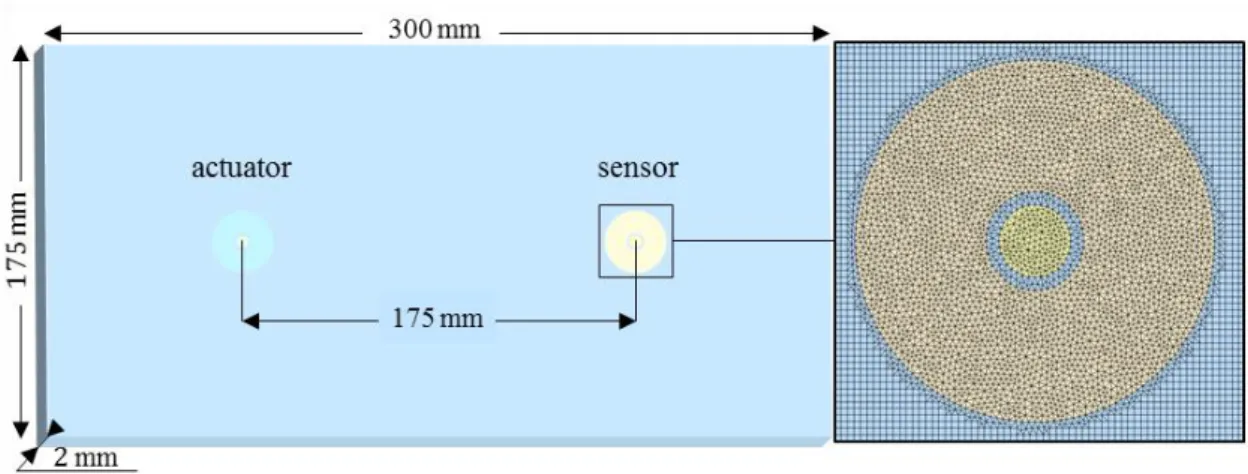
3.1 Simulation parametersThe Finite Element Model (FEM) is built with SDTools® (33) (see Figure 4). The implemented structure is a 300 × 175 × 2 mm3, [0°, 90°]
16 CFRP plate with properties given in table 2. It is modeled as a 3D orthotropic material and homogenized using Mindlin theory for thin laminate plates.
Table 2: Properties of one layer (carbon fiber + epoxy matrix) of the CFRP composite laminate.
𝑬𝟏 [GPa] 𝑬𝟐 = 𝑬𝟑 [GPa] 𝝂𝟑𝟏 𝝂𝟐𝟑= 𝝂𝟏𝟐 𝑮𝟐𝟑 [GPa] 𝑮𝟑𝟏 [GPa] 𝑮𝟏𝟐 [GPa] 𝝆 [kg. m−3] 121 8.6 0.06 0.31 4.3 4.3 5.9 1520
The plate is mounted with two dual PZT placed 175 mm from each other with dimensions obtained via the sizing method proposed in previous parts (∅𝑃𝑍𝑇−𝑑𝑖𝑠𝑘 = 5.5 mm, ∅𝑃𝑍𝑇−𝑟𝑖𝑛𝑔𝑖𝑛𝑛𝑒𝑟 = 7.5 mm and ∅
𝑃𝑍𝑇−𝑟𝑖𝑛𝑔
𝑜𝑢𝑡𝑒𝑟 = 27.5 mm). The PZT elements are composed of Noliac NCE51 material (see properties in table 3) and simulated as piezoelectric shell finite elements. The electromechanical interaction and the effect of glue and temperature for proposed PZT elements implemented in SDTools® have been experimentally validated in previous experiment (34,35).
Table 3: Electro-mechanical properties of the PZT material NCE51 from Noliac.
𝑬𝟏𝟏 [GPa] 𝑬𝟑𝟑 [GPa] 𝒂 [1/K] 𝝂 𝒅𝟑𝟏 [pC/N] 𝒅𝟑𝟑 [pC/N] 𝒔𝟏𝟏𝑬 . 𝟏𝟎−𝟏𝟐 𝒔𝟑𝟑 𝑬 . 𝟏𝟎−𝟏𝟐 [kg. m𝝆 −3] 62.50 52.63 2. 10−6 0.38 −195.00 460.00 16.00 19.00 7600
Quadratic elements with dimension 0.5 mm × 0.5 mm are used for the meshing of the plate. This mesh size has been validated by a convergence test and is compatible with the wavelength of the 𝐴0 and 𝑆0 mode which value does not exceed 11 mm on the investigated frequency range. The excitation signal is a 5 cycles sinusoidal tone burst of amplitude 10 V modulated by a Hanning window at a central frequency 𝑓0 alternatively equal to 50, 100 and 150 kHz (two values in the proposed frequency range from 𝑓𝐴0 to
𝑓𝑆0 in figure 3, and one outside). Simulations are conducted with each possible emission scheme (entire PZT, ring part, disk part). The time step for the transient simulation is 0.5 µs (equivalent to a sampling frequency of 2 MHz). The transient simulation is performed using Newmark’s method and the structure dynamic damping is simulated by considering a coefficient of 5.10−8 for the stiffness matrix. No damping coefficient is considered for the mass matrix.
Figure 4: FEM composite plate with two dual PZTs (left) and mesh of the dual PZT (right)
3.2 Difference of sensitivity of dual PZT parts
As explained in the first part of this article, the sensitivity of each part of the dual PZT to a specific wavelength depends on its dimensions. Therefore, since 𝐴0 and 𝑆0 modes have different wavelength for a given excitation frequency (see Figure 3), each part of the dual PZT has a different sensitivity to each modes.
Figure 5: Time response obtained for ring (𝑽𝒓𝒊𝒏𝒈→𝒓𝒊𝒏𝒈) and disk ( 𝑽𝒓𝒊𝒏𝒈→𝒅𝒊𝒔𝒌) part of the dual PZT at excitation frequencies of 𝟓𝟎, 𝟏𝟎𝟎 and 𝟏𝟓𝟎 kHz. 𝐓𝐨𝐀𝑨𝟎 and 𝐓𝐨𝐀𝑺𝟎 are the Time of
Arrival of modes 𝑨𝟎 and 𝑺𝟎.
Figure 5 shows time response signals obtained with different excitation frequencies. Time of Arrivals of both modes (ToA𝐴0 and ToA𝑆0) are determined from displacement of nodes
of the FEM simulation at the center of the dual PZT (in-plane displacement for 𝑆0, out-of-plane displacement for 𝐴0). Those signals emphasize the need for mode decomposition in this case since the 𝐴0 mode superposes with reflections of 𝑆0 mode on the plate edges. It also confirms that the disk part of the dual PZT is more sensible to the 𝐴0 mode at any excitation frequency: ∅𝑃𝑍𝑇−𝑑𝑖𝑠𝑘 is smaller than ∅𝑃𝑍𝑇−𝑟𝑖𝑛𝑔, hence it is more sensible to smaller wavelength (Eq.(3)), and 𝐴0 wavelength is always smaller to 𝑆0 wavelength on the considered frequency range. It is also noticeable that 𝐴0 mode attenuates more at 150 kHz. In fact, 𝐴0 mode barely propagate at this excitation frequency (observation from FEM results), and both part of the dual PZT are not supposed to be sensitive to the wavelength of 𝐴0 mode at this frequency (corresponding to the 3rd part of Figure 3).
3.3 Mode decomposition
The mode decomposition method using dual PZT is described in [15]. It is based on a combination of the 9 time responses - corresponding to different pairing of entire, ring and disk parts of dual PZT actuator and sensor - obtained on a given path. For an efficient application of this method, dual PZT should be placed far enough to prevent mode superposition of the first wave packet in the time response. In previous applications (12– 17), dual PZT were placed away from the edges to guarantee optimal isolation of modes in time responses. It is somewhat possible to apply the decomposition method efficiently as far as the first wave packet of the 𝑆0 mode is distinguishable from the rest of the time response signal.
Figure 6: Time responses obtained with disk part as actuator and disk part as sensor for an excitation frequencies of 𝟓𝟎 kHz (left) and 𝟏𝟎𝟎 kHz (right) and isolated contributions of 𝑨𝟎 (red)
and 𝑺𝟎 (blue) mode with the dual PZT method.
Figure 6 shows the result of mode decomposition applied to the time response for excitation frequencies of 50 and 100 kHz. Modes isolation works well despite their superposition in the signal measured. Contrary to (14), no extra matching pursuit algorithm has been applied to isolated contributions. Results obtained for an excitation frequency of 100 kHz brings out some interesting phenomena:
Since 𝐴0 wave packet superposes with reflections of 𝑆0 wave packet, they are cancelled in the time response signal 𝑉𝑑𝑖𝑠𝑘→𝑑𝑖𝑠𝑘, but the mode decomposition method enables the visualisation of both modes.
The 𝐴0 mode contribution seems to fail if the beginning of the signal is considered (before the arrival of 𝐴0 main wave packet). However, a preview of the displacement obtained with the simulation help to understand the meaning of this perturbation: Figure 7 shows that mode conversion happens when 𝑆0 wave reach the ring part of the dual PZT (see displacement obtained at ToA𝑆0).
3.4 Influence of plies orientation
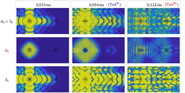
The orientation of plies in a highly anisotropic material has a great influence on wave propagations. Figure 7 shows the displacement of nodes from the FEM simulation for an excitation frequency of 100 kHz. The time response obtained on the dual PZT sensor for this simulation are displayed in Figure 5. These pictures illustrates that 𝐴0 wave as a smaller wavelength than 𝑆0 wave and propagates much slower. It brings out that 𝑆0 mode amplitude and speed is much more affected by the plies orientations than the 𝐴0 mode (obvious on observations at 0.033 ms): its amplitude is maximum in fibers direction (0° and 90°) and weaker for other orientations. It also illustrates that several reflections of the 𝑆0 mode reach the dual PZT sensor when 𝐴0 mode arrives (observations at 0.122 ms).
Figure 7: Displacement of nodes of the FEM simulation obtained for an excitation frequency of
𝟏𝟎𝟎 kHz at three different moments. 𝑨𝟎 and 𝑺𝟎 mode amplitude are assumed to correspond respectively to out-of-plane and in-plane displacements.
Since the 𝑆0 wave amplitude is greatly attenuated outside composite fiber orientations (0° and 90°), the decomposition method is impacted in situations where the 𝑆0 mode wave packet can’t be figured out in the time response.
Figure 8 compares signals obtained at a same distance between transducers (175 mm) but considering an angle θ of 0° and 45° between the actuator-sensor path and the 0° ply orientation of the composite material. For θ = 45°, 𝑆0 mode first wave packet is negligible compared to 𝐴0 mode, on contrary to the results obtained for θ = 0°. However, larger amplitude of 𝑆0 mode is obtained for θ = 45° than θ = 0° when edges reflections of 𝑆0 wave and converted 𝐴0 wave at the boundaries reach the sensor.
Figure 8: Comparison of time response signals and isolated modes obtained with disk part as actuator and disk part as sensor for 𝒇𝟎= 𝟓𝟎 kHz, and an angle 𝛉 of 𝟎°(grey curves) and 𝟒𝟓°
between the actuator-sensor path and the 𝟎° ply orientation of the composite.
Conclusions
Dual PZT are used to isolate 𝐴0 and 𝑆0 mode contribution in signals obtained for a pair of transducers. The current work presents a method to size dual PZTs electrodes (ring and disk), and find appropriate excitation frequencies based on Lamb Wave dispersion curves. This method is applied on the sizing of dual PZT bounded to a highly anisotropic composite plate (CFRP [0,90]16).
A FEM transient simulation is then performed in order to apply the mode decomposition technique on the investigated plate mounted with two dual PZT.
Mode contributions are successfully isolated despite the anisotropy of the material and the superposition of edges reflections in time response obtained. These results are promising for the application of baseline free damage indicators based on the study of the relative variation of modes (amplitude, shape or delay). However, presence of both mode in the response are needed in order to apply the decomposition technique. This parameter must be taken into account in the dual PZT network design and the choice of the excitation frequency.
Future studies will focus on experimental validation of results obtained in this article and the study of the influence of different kind of damages on each mode.
References
1. Worden K, Farrar CR, Manson G, Park G. The fundamental axioms of structural health monitoring. Proc R Soc Math Phys Eng Sci. 2007 Jun 8;463(2082):1639–64. 2. Michaels JE, Michaels TE. Detection of structural damage from the local temporal
coherence of diffuse ultrasonic signals. IEEE Trans Ultrason Ferroelectr Freq Control. 2005 Oct;52(10):1769–82.
3. Roy S, Lonkar K, Janapati V, Chang F-K. A novel physics-based temperature compensation model for structural health monitoring using ultrasonic guided waves. Struct Health Monit. 2014;13(3):321–342.
4. Wang Y, Gao L, Yuan S, Qiu L, Qing X. An adaptive filter-based temperature compensation technique for structural health monitoring. J Intell Mater Syst Struct. 2014 Nov 1;25(17):2187–98.
5. Wang Y, Qiu L, Gao L, Yuan S, Qing X. A new temperature compensation method for guided wave-based structural health monitoring. In: Kundu T, editor. 2013 [cited 2016 May 30]. p. 86950H.
6. Konstantinidis G, Drinkwater BW, Wilcox PD. The temperature stability of guided wave structural health monitoring systems. Smart Mater Struct. 2006 Aug 1;15(4):967–76.
7. Lu Y, Michaels JE. A methodology for structural health monitoring with diffuse ultrasonic waves in the presence of temperature variations. Ultrasonics. 2005 Oct;43(9):717–31.
8. Su Z, Ye L. Identification of damage using Lamb waves: from fundamentals to applications. Berlin: Springer-Verlag; 2009. 346 p. (Lecture notes in applied and computational mechanics).
9. Lammering R, Gabbert U, Sinapius M, Schuster T, Wierach P, editors. Lamb-Wave Based Structural Health Monitoring in Polymer Composites [Internet]. Cham: Springer International Publishing; 2018 [cited 2018 Feb 26]. (Research Topics in Aerospace).
10. Sohn H, Lim HJ, Yeum CM, Ihn J-B. Reference free inconsistency detection system [Internet]. Google Patents; 2015 [cited 2016 Sep 14].
11. An Y-K, Sohn H. Instantaneous crack detection under varying temperature and static loading conditions. Struct Control Health Monit. 2010 Nov 1;17(7):730–41. 12. Yeum CM, Sohn H, Ihn JB. Delamination detection in a composite plate using a
dual piezoelectric transducer network. In: Kundu T, editor. 2011 [cited 2016 Sep 27]. p. 798406.
13. Yeum CM, Sohn H, Ihn JB, Lim HJ. Instantaneous delamination detection in a composite plate using a dual piezoelectric transducer network. Compos Struct. 2012 Dec;94(12):3490–9.
14. Yeum CM, Sohn H, Lim HJ, Ihn JB. Reference-free delamination detection using Lamb waves. Struct Control Health Monit. 2013 Aug.
15. Yeum CM, Sohn H, Ihn JB. Lamb wave mode decomposition using concentric ring and circular piezoelectric transducers. Wave Motion. 2011 Jun;48(4):358–70. 16. Sohn H, Kim SB. Development of dual PZT transducers for reference-free crack
detection in thin plate structures. IEEE Trans Ultrason Ferroelectr Freq Control. 2010 Jan;57(1):229–40.
17. Lim HJ, Sohn H, Yeum CM, Kim JM. Reference-free damage detection, localization, and quantification in composites. J Acoust Soc Am. 2013 Jun 1;133(6):3838–45.
18. Anton SR, Butland A, Carrión M, Buechler M, Park G. Instantaneous Structural Damage Identification Using Piezoelectric-Based Lamb Wave Propagation. Proc IMAC-XXV Febr. 2007;19–22.
19. Anton SR, Inman DJ, Park G. Reference-Free Damage Detection Using Instantaneous Baseline Measurements. AIAA J. 2009 Aug;47(8):1952–64.
20. Alem B, Abedian A, Nasrollahi-Nasab K. Reference-Free Damage Identification in Plate-Like Structures Using Lamb-Wave Propagation with Embedded Piezoelectric Sensors. J Aerosp Eng. 2016 Jul 14;04016062.
21. Bagheri A, Li K, Rizzo P. Reference-free damage detection by means of wavelet transform and empirical mode decomposition applied to Lamb waves. J Intell Mater Syst Struct. 2013 Jan 1;24(2):194–208.
22. Sohn H, Woo Park H, Law K, Farrar CR. Combination of a Time Reversal Process and a Consecutive Outlier Analysis for Baseline-free Damage Diagnosis. J Intell Mater Syst Struct [Internet]. 2006 Dec 13;
23. Sohn. Damage Detection in Composite Plates by Using an Enhanced Time Reversal Method. 2007.
24. Park HW, Sohn H, Law KH, Farrar CR. Time reversal active sensing for health monitoring of a composite plate. J Sound Vib. 2007 Apr;302(1–2):50–66.
25. Gangadharan R, Murthy CRL, Gopalakrishnan S, Bhat MR. Time reversal health monitoring of composite plates using Lamb waves. Int J Aerosp Innov. 2011;3(3):131–142.
26. Liu Z, Zhong X, Dong T, He C, Wu B. Delamination detection in composite plates by synthesizing time-reversed Lamb waves and a modified damage imaging algorithm based on RAPID. Struct Control Health Monit. 2016 Jan 1;
27. Park HW, Kim SB, Sohn H. Understanding a time reversal process in Lamb wave propagation. Wave Motion. 2009 Nov;46(7):451–67.
28. Kim SB, Sohn H. Instantaneous crack detection using dual PZT transducers. In: Kundu T, editor. 2008 [cited 2016 Nov 28]. p. 693509.
29. Huang L, Zeng L, Lin J. Baseline-free damage detection in composite plates based on the reciprocity principle. Smart Mater Struct. 2018 Jan 1;27(1):015026.
30. Lamb H. On waves in elastic plates. 1917;
31. Rose JL. Ultrasonic Waves in Solid Media. Cambridge University Press; 2004. 32. Raghavan A, Cesnik CES. Finite-dimensional piezoelectric transducer modeling for
guided wave based structural health monitoring. Smart Mater Struct. 2005 Dec 1;14(6):1448–61.
33. Balmes E, Bianchi J, Leclere J. Structural Dynamics Toolbox 6.2 (for use with MATLAB), SDTools, Paris, France. [Internet]. 2009 [cited 2017 Dec 12].
34. Balmes E, Guskov M, Bianchi J-P. Validation and verification of FE models of piezo based SHM systems. In: ISMA International Conference on Noise and Vibration Engineering [Internet]. Leuven, Belgium; 2016. p. ID 807.
35. Fendzi C, Rébillat M, Mechbal N, Guskov M, Coffignal G. A data-driven temperature compensation approach for Structural Health Monitoring using Lamb waves. Struct Health Monit Int J. 2016 Sep;15(5):525–40.