To cite this version :
Romain PINQUIE, Louis RIVEST, Philippe VERON, Frédéric SEGONDS - An illustrated glossary of ambiguous PLM terms used in discrete manufacturing - International Journal of Product Lifecycle Management - Vol. 8, n°2, p.142-171 - 2015
An illustrated glossary of ambiguous PLM terms used
in discrete manufacturing
Romain Pinquié*
Laboratoire des Sciences de l’Information et des Systèmes, UMR CNRS 7296,
Arts et Métiers ParisTech, 2, cours des Arts et Métiers, 13617 Aix-en-Provence, France Email: romain.pinquie@ensam.eu *Corresponding author
Louis Rivest
Départment de génie de la production automatisée, École de technologie supérieure,
1100 rue Notre-Dame ouest,
Montréal, Québec H3C 1K3, Canada Email: louis.rivest@etsmtl.ca
Frédéric Segonds
Laboratoire Conception de Produits et Innovation, Arts et Métiers ParisTech,
151, Boulevard de l’Hôpital, 75013 Paris, France Email: frederic.segonds@ensam.eu
Philippe Véron
Laboratoire des Sciences de l’Information et des Systèmes, UMR CNRS 7296,
Arts et Métiers ParisTech, 2, cours des Arts et Métiers, 13617 Aix-en-Provence, France Email: philippe.veron@ensam.eu
Abstract: Product lifecycle management (PLM) is a strategic product-centric,
lifecycle-oriented and information-driven business approach that strives to integrate people and their inherent practices, processes, and technologies, both within and across functional areas of the extended enterprise from inception to disposal. The integration of people relies on the harmonisation of domain-specific glossaries by standardising a universal PLM vocabulary. So far, unfortunately, there is no PLM standard vocabulary. Therefore, the tremendous amount of knowledge that is continually brought forward by academic research studies, industrial practices and computer-aided applications causes semantic ambiguities. This paper consists of an illustrated glossary and a
conceptual map. The glossary identifies, discusses, clarifies and illustrates ambiguous terms used in discrete manufacturing. The conceptual map finally underlines the logical flow of refereed definitions.
Keywords: product lifecycle management; PLM; ambiguous terms; discrete
manufacturing; illustrated glossary; unified PLM vocabulary
Reference to this paper should be made as follows: Pinquié, R., Rivest, L.,
Segonds, F. and Véron, P. (2015) ‘An illustrated glossary of ambiguous PLM terms used in discrete manufacturing’, Int. J. Product Lifecycle Management, Vol. 8, No. 2, pp.142–171.
Biographical notes: Romain Pinquié is a PhD student at the Arts et Métiers
ParisTech Engineering School in Aix-en-Provence, France. He received his MSc in Computational and Software Techniques in Engineering, specialising in Computer Aided Engineering from Cranfield University. His research concentrates on requirements engineering, combining aspects of systems theory and data science to support the design of complex systems.
Louis Rivest became a Professor at Ecole de Technologie Superieure in Montreal, Canada, after spending a few years in the aerospace industry. He obtained his PhD from Ecole Polytechnique de Montreal in 1993, and Bachelor in Mechanical Engineering in 1988. His research centres on the models, methods, tools and processes supporting complex product development. Currently, his work is applied primarily in the aerospace field. His teaching and research activities thus relate to CAD, especially geometric comparison, product data management and PLM.
Frédéric Segonds is an Assistant Professor at Arts et Metiers ParisTech and a member of the Product Design and Innovation Laboratory (LCPI). His research interests focus on the early stages of design collaboration, optimisation and collaborative design. This area includes the integration of stakeholder’s core competences into the early stages of design, and providing methodologies and tools to support early product design.
Philippe Véron is a Full Professor at the Arts et Métiers ParisTech engineering school in Aix-en-Provence, France and a member of the Information and Systems Science Laboratory (LSIS, CNRS unit no. 7296). Currently, he is also the Head of the Research and Training Department of Design and Production Engineering, Risk Management and Decision-Making. His main research interests are on the development of geometric modelling approaches in the context of a multi-view and integrated design environment. He also has a particular interest in multi-site collaborative design product approaches.
1 Introduction
1.1 Product lifecycle management as a well-established discipline
Even though companies have always, more or less efficiently, managed their products throughout their entire lives (Stark, 2007), the processes and tools that were usually employed did not enable them to develop and commercialise high-quality, cost-effective products with an optimised time-to-market. Academic researchers and industrial
companies have therefore progressively worked out a set of theoretical and practical best practices, forming a new discipline: product lifecycle management (PLM).
Referring to the industrial context, the origins of PLM can be roughly associated with the integration of various computer aided technologies, especially computer aided design (CAD), product data management (PDM), computer integrated manufacturing (CIM) and engineering data management (EDM) tools (Grieves, 2005). This merging enabled the implementation of the collaborative vision of concurrent engineering (Terzi et al., 2010). From the information and communications technologies (ICT) perspective, PLM is an inter-organisational enterprise level software application that intends to integrate more and more technologies so as to streamline the flow of product information across the extended enterprise – i.e., across the entire organisation and into the supply chain – all through the product’s life (Terzi et al., 2010). Nevertheless, PLM goes far beyond CAX and PDM. PLM is a form of lean thinking from the product cradle to its grave (Grieves, 2005). PLM is the “the product viewpoint of the whole business” (PLM Interest Group, 2014). Indeed, from a broader business perspective, the enterprise level software application supports a strategic product-centric, lifecycle-oriented and information-driven (Grieves, 2005) business approach (Terzi et al., 2010), whose purpose is to reduce costs, shorten time-to-market and improve quality by integrating people and their inherent practices, processes, and technologies, both within and across functional areas of the extended enterprise; and, more recently, by capitalising on product-related knowledge throughout a product’s life.
From an academic point of view, the official origins of PLM can be traced back to the First PLM International Conference in 2003. Subsequently, in 2005, the International Journal in Product Lifecycle Management (IJPLM) was created to provide researchers with the opportunity to promote and share their scientific contributions with the PLM community.
1.2 Semantic ambiguities due to the popularisation of PLM
Putting the PLM discipline within every business’ reach leads to various semantic ambiguities. Ambiguities are of two forms; either one single term identifies two dissimilar concepts (polysemy), or, conversely, at least two distinct terms refer to the same concept (synonymy). When talking about a ‘concept’ in this article, we mean a unit of knowledge that can be expressed by a term. Most industries (aerospace, automotive, civil engineering, pharmaceutical, green energy, life sciences, apparel design, etc.) have understood the benefits that PLM brings (Segonds et al., 2012, 2014). It is however not the norm that two industries use the same specific terms to talk about the same PLM concept – i.e., a unit of knowledge that belongs to the PLM discipline. Moreover, the diversity of the PLM community, which includes academics and industrialists, software providers and end users, managers and engineers, is another reason why the standardisation of a universal terminology is so challenging. For instance, because PLM strategy rests upon an extensive use of CAX tools, the PLM vocabulary is under the influence of software-implemented terms. To sum up, although PLM is identified as an established branch of knowledge, we nevertheless deplore the lack of standards in establishing a common language that removes semantic ambiguities.
1.3 Our contribution
This paper proposes a unified understanding of ambiguous PLM terms used in discrete manufacturing.
This list does not intend to define all terms of the PLM discipline, but rather focuses on ambiguous terms; therefore, it is a subset of the incommensurable PLM lexicon.
Manufacturing can be qualified as either discrete – i.e., the production of discrete items (e.g., cars, aircraft and appliances) – or continuous process, i.e., the production process that lends itself to an endless flow of non-discrete product (e.g., pharmaceutical, food and beverage, chemicals and cosmetics) (ISO, 2004). The ambiguous terms that we discuss are more commonly used in discrete manufacturing. This is not a coincidence; to date, a PLM approach is much more frequently applied to discrete products rather than formulated ones. Indeed, a quantitative review of the proceedings presented at the IFIP WG 5.1 10th and 11th international conference on PLM (PLM13 and PLM14) concludes that only 3 papers explicitly broach the topic of a product created in a continuous process flow, whereas 45 deal with a discrete product. To categorise, we sought after distinguishing keywords in the title, abstract and case study. Terms such as aeronautics, boat, marine, apparel, fashion industry, automotive, washing machines, heavy machinery industries, luxury industry, naval engineering are categorised as discrete manufacturing; whereas the keywords pharmaceutical, fertiliser industry, biomedical belong to the continuous process category. Papers that deal with too-generic issues such as CAD, CAM, 3D printing, business practices, generic data model, maturity models or metrics are unclassified.
Because the reuse of words implemented in software technologies is one major cause of ambiguity, the suggested glossary may seem to reduce PLM to the merging of CAX and PDM. However, Section 1.1 points out that such a definition is only acceptable from an ICT point of view. Nevertheless, the tight relationship between ‘PLM as a business strategy’ and ‘PLM as an enterprise level software application’ tends to blur the differences between their respective lexicons. Consequently, we argue that both points of view shall rely upon a common vocabulary; therefore, the list of refereed definitions that we propose suits both perspectives.
As a PLM approach integrates processes and technologies, this initial step towards the standardisation of a PLM terminology facilitates the integration of people. For instance, this glossary eases: the collaboration among the various experts who are brought together by common PLM interests; the arrival and integration of new talents within the PLM community; the introduction of key PLM concepts to the 1st year PhD students; and the gathering of knowledge that has been independently acquired in PLM and building information modelling (BIM) disciplines.
In Section 2, we identify, discuss, define and illustrate ambiguous PLM terms used in discrete manufacturing. Thus, each PLM unit of knowledge that was originally ambiguous is uniquely labelled, defined and illustrated. Finally, we propose a conceptual map that logically illustrates the consistency of the refereed definitions and outlines the contextual interdependencies among the concepts.
2 Clarification of ambiguous PLM terms used in discrete manufacturing This chapter is a list of PLM concepts used in discrete manufacturing and whose labels and/or definitions are ambiguous. The identification of ambiguous terms is based on an extensive literature review of the PLM discipline during which we addressed the polysemy and synonymy of keywords. Each concept is discussed according to a template. First, for a given concept, a literature review highlights its ambiguities as well as the most relevant characteristics that help to define it. Secondly, a unique definition is suggested. Finally, the example of a bicycle is systematically used to illustrate the refereed definition.
2.1 Product
Often limited to its tangible (hardware, physical) aspect, the product as it is considered in PLM can also be intangible (software, algorithm, equation, etc.) (Kahn, 2013; Saaksvuori and Immonen, 2008; Stark, 2011). Services, as defined by industry standards (ISO, 2005) are more and more admitted as an integral part of the product (ISO, 2005; Saaksvuori and Immonen, 2008; Terzi et al., 2010; Stark, 2011). According to Rivière (2004), the product definition may also include the environment in which the product operates. For instance, Rivière (2004) reports that in the aerospace field, the design of a rocket implicitly includes the design of the launching and control premises. He also mentions that the mission of the rocket cannot be separated from the rocket itself. Stark (2011) states that “the product packaging, labelling, literature, user or regulatory documentation, wires and plugs, delivery mechanism are also part of the product, like a six-pack is a product of six single products”.
Figure 1 Product (see online version for colours)
Definition – Product: the result of a process, that is, the result of a set of interrelated or interacting activities that transform inputs into outputs (ISO, 2005). A product can be tangible and/or intangible. An intangible product can be a service or not a service. A product can be a sum of products. A product can include the products which constitute the environment in which it operates. A product can include the missions it must fulfil. Generally a product is a blend of these properties.
2.2 Product lifecycle and milestones
Various definitions of the term product lifecycle exist, but it can be normalised as a sequence of three main phases in a product’s life: beginning-of-life (BOL), middle-of-life (MOL) and end-of-life (Terzi et al., 2010; Stark, 2011). The number and type of phases that make up each main phase vary according to product, manufacturer(s) and customer(s) constraints. In their definition of product lifecycle, Terzi et al. (2010) state that the BOL includes the design and manufacturing phases; the MOL consists of the distribution, use and support; and, finally, the EOL corresponds to the retirement of the product, which can either be its recycling or its disposal. Within the BOL we insert the industrialisation phase between design and manufacturing (Khedher et al., 2010) so as to take the manufacturing deviations into consideration. Stark (2011) indicates that the product lifecycle changes according to the stakeholder viewpoint since, for instance, the phase before last is the use of the product from a stakeholder’s perspective, whereas the manufacturer focuses on the support.
The boundaries that characterise the transitions from one phase of a product lifecycle to another are known as milestones. Milestones designate a project’s or program’s status (ISO, 2007). They are pre-determined significant points in a project which are used to indicate, measure and track the amount of progress made toward a project’s completion during the product lifecycle (ISO, 2007, 2010b; Puechoultres, 2013). As-X terms such as as-required, as-proposed, as-specified, as-contracted, as-defined, as-designed, as-planned, as-built, as-qualified, as-delivered, as-operated, as-maintained, as-disposed, etc. are commonly used to refer to these checkpoints (Mas et al., 2013a).
Definition – Product lifecycle: conceptual sequence of phases that describes the product’s life.
Definition – Milestone: particular instant t of the product lifecycle.
Figure 2 Product lifecycle and milestones (see online version for colours)
2.3 Technical object
A product can be seen as a sum of constituents whose nature changes throughout the product lifecycle. At the beginning of a project, the nature is defined as a customer need, which is then specialised as a requirement, after which the nature becomes a function, a design artefact, a physical hardware and/or software object, etc. To talk about a product and its constituents independently of their successive natures, systems engineering came up with terms such as building block, end products, subsystems and enabling product (EIA, 1999), or system and system element (ISO, 2008). However, the underlying concepts of these terms depend on their level within the product architecture. The only
common denominator that makes abstraction of both the nature and the architecture level is the technical object (Maurino, 1994). By looking at the 43 citations to Maurino’s book listed by Google Scholar, we notice that the term technical object mainly occurs in the French literature, and this is perhaps the reason why it never broke into the international community despite its usefulness. A technical object is any useful identifiable element of a product (Tremblay et al., 2006) whose nature evolves. Thus, each function of a company works and communicates by using a different viewpoint that provides the suitable nature of a selected technical object. Companies define and use their own natures, which vary according to the type of products they develop, their activities, culture, etc. Nevertheless, Maurino (1994) lists three main natures of a technical object: function, design object and manufactured object (and a bundle of manufactured objects). From a PDM perspective, a technical object is analogous to a node in a product structure. Finally, the assembly of several technical objects is also a technical object, since the whole product is, in a recursive manner, a technical object.
Definition – Technical object: a conceptual artefact that identifies components independently of their nature and their architectural level.
Figure 3 Technical objects (see online version for colours)
2.4 Product data and product metadata
As mentioned by NASA (2007), the terms data and information are frequently used interchangeably. Nevertheless, Zins (2007) compiled a literature review that reveals relevant characteristics to distinguish both terms. Data are meaningless recorded raw things (materials, facts, characters, symbols, numbers, and symbolic entities), which result from an observation or measurement process. Data can be stored, processed, transmitted, quantified and measured, but they need to be contextualised to be interpreted. In other words, they are unprocessed (pre-processed or post-processed) information. On the other hand, information is an organised collection of processed data, together with their relationships. Information can be communicated, or is at least available for communication. To become information, data must not only be aggregated
and contextualised, but also connected with an interpretor so as to become meaningful. An interpretor is either a human being or an artificial processing unit (ISO, 1994). Product data includes all the data related to a product and to its associated processes throughout the product’s life (Stark, 2011). They are formalised in a structured manner suitable for communication, interpretation and processing (ISO, 1994), and are managed by PDM tools, which have been extended to PLM tools (Saaksvuori and Immonen, 2008). We suggest differentiating the product data from the technical data. The latter includes not only product-centred data (managed in PDM/PLM), but also customer relationship data (managed in CRM), enterprise resource data (managed in ERP), and supply-chain data (managed in SCM). In PLM, product data is broadly similar to digital documents that store product-centric data with their associated metadata, or strictly speaking, product metadata that gives additional high-level details with regard to the digital documents, such as the author’s name, creation date, level of security, etc. Product data is comparable to the concept of document used by Maurino (1994), which is attached to a technical object, and whose purpose is to describe it. Thus, in a PLM tool, the nodes of the graph serve to access product data by either binding digital documents, or by inputting product metadata.
Definition – Product data: all documents, mostly numerical, that store product-centric data related to a technical object and its associated processes recorded in a form that is suitable for processing by human beings or by artificial processing units, and their associated product metadata.
Definition – Product metadata: data about documents, mostly numerical, that store product-centric data.
2.5 Variant VS option 2.5.1 Variant
Agard (2004) describes a variant as a one-to-many (1:N) cardinality, which means that a product has at least one variant, although several variants may exist. A variant is analogous to an instance of a class that exhibits slight differences (ElMaraghy et al., 2013; Jiao et al., 2007), and as a variation of a basic working product (Stark, 2011). Several variants can coexist (Männistö, 2000), sharing standardised characteristics (Jiao et al., 2007). If a variant is a component, then it must have common interfaces with the connected component(s) (Erens and Verhulst, 1997). The Dassault Systèmes’ (2011) PLM solution ENOVIA V6 uses the term design variants that is confusing, since the concept of variant is not limited to the design phase.
Definition – Variant: instance of a technical object, or of a set of technical objects, which shows slight differences and that shares compatible standardised characteristics with other variants. A variant results from an exclusive choice (1:1), which allows the customer to only pick one variant among the list of variants.
Figure 5 Variants (see online version for colours)
2.5.2 Option
Options are additions to the basic characteristics of a product (Chambolle, 1999; Stark, 2011), or more precisely, additions to a specific variant of a product. Agard (2004) indicates that options can be described by an optional zero-to-many (0:N) cardinality. Definition – Option: unnecessary characteristic(s) that result from a non-exclusive choice (0:N), which allows a customer to add none, one, or several options to a variant.
2.6 Product diversity
As shown hereafter, it is very common to find terms relating to the semantic field of the term configuration – e.g., configuration, configurable product, configured product – as a means to refer to variants and options. Furthermore, Debaecker (2013) and the PLM Lab (2011) rightly report that configuration management (CM) is sometimes the preferred to discuss the activities that enable companies to manage variants and options.
Figure 6 Options (see online version for colours)
2.6.1 Customised product
The denomination of a product that is tailored to meet specific customer requirements is often based on the term configuration. The terms configured product (Felfernig et al., 2001; Männistö et al., 2001; Tiihonen et al., 1998), configuration (Callahan, 2006; Männistö, 2000; Veron, 2001) and specific configuration (Izadpanah et al., 2009) are employed in the literature to distinguish a particular instance (Jiao et al., 2007) resulting from the choice of a variant with potential option(s). According to Ducellier (2008), a product family can be filtered in order to identify a configuration, that is, a consistent set of parts that form a product. Nevertheless, we will see in 2.9 that a configuration is not merely a combination of variants and option(s). Jiao et al. (2007) and Dassault Systèmes (2011) prefer the terms variant and product variant, respectively, but as indicated above, a variant is different than an option, whereas a customised product considers both. The commercialised product is either a variant or the combination of one product variant with one or several options. The outcome of both alternatives is a product that is customised according to customer expectations. Therefore, we suggest to simply label this concept as a customised product.
Definition – Customised product: one particular combination of one product variant with one or several options.
Figure 7 Customised product (see online version for colours)
2.6.2 Customised products family
A set of products that requires a customer to choose one variant and eventually one or several options is often called a products family (Agard, 2004; Callahan, 2006;
O’Donnell et al., 1996; ElMaraghy et al., 2013; Erens, 1996; Jiao et al., 2007; Mtopi Fotso et al., 2009). Whereas Hsiao et al. (2013) prefer the name of modular product, it is frequent to come across terms that belong to the semantic field of the noun configuration, such as configurable product (Männistö et al., 2001; Tiihonen et al., 1998) and generic configuration (Izadpanah et al., 2009). As explained in the previous section, the term configuration and its derived forms are broader than the concepts of product diversity. A products family is an unambiguous term to define a structured collection of customised products. To be even more rigorous and consistent with the definition of a customised product, we prefer to use the term customised products family.
Definition – Customised products family: a set of pre-defined customised products that share a standardised basis.
Figure 8 Customised products family (see online version for colours)
2.6.3 Product diversity management
Männistö (2000) reports that the term configuration is also alternatively employed to either refer to the process used to specify a customised product from a customised products family (O’Donnell et al., 1996; Felfernig et al., 2001), or to refer to a customised product (Callahan, 2006; Männistö, 2000; Veron, 2001). The set of activities that consists in selecting a customised product from a customised products family is also known as the configuration process (Brière-Côté et al., 2010; Männistö et al., 2001; Tiihonen et al., 1998) and as CM. However, once again, for the reasons given in 2.6.1 and 2.6.2, we prefer to adopt the expression product diversity management to refer to the activities used to manage a customised products family.
Definition – Product diversity management: a set of correlated activities designed to maintain a consistent definition of each customised product within a customised products family.
2.7 Version, design alternatives, revision, iteration
As Männistö (2000) reports, the terms version, alternative, revision and variant are used alternatively, but we observe that they do not have the same meaning. For instance, the CIMdata PLM Glossary (CIMdata, 2014) considers the version and the variant of a product as synonyms, whereas Männistö (2000) does not.
2.7.1 Version, revision, engineering change process and iteration
Sometimes a version is considered to be similar to a customised product (Dolezal, 2008). However, according to Männistö (2000), a version characterises the temporal evolution of a product. Stark (2011) also defines a version as time-dependent, because it characterises a set of product features and functions at a certain time. This definition is similar to the definition given by the ENOVIA V6 glossary (Dassault Systèmes, 2011): “an object is versioned when its fit, form or function is changed”. This is only acceptable from a physical or functional perspective. In other words, the modification of any existing technical object’s property, or the addition of a new property leads to the creation of a new version of the technical object. Admittedly, the concept of version refers to the particular state of a technical object, however, to be precise, it characterises the state of a product’s data that defines it.
In product design, iterations are repetitive activities that encompass multiple passes to converge to a suitable design solution (Dolezal, 2008), that is, a new version of the product data that defines a technical object. The creation of a new version is sometimes the result of one iteration, but generally, because not every design iteration is associated with a version (Puechoultres, 2013), the creation of a new version usually requires several design iterations. In general, it is the release of a set of design iterations that gives birth to a new version of a product data.
According to Männistö (2000), the change process that consists of creating a new version from an old one is called revision. In this particular case, the terms revision and engineering change process, which is also known as product change process or document change process (Stark, 2011), are two synonyms. As the new version N+1 of a product’s data is generally an improvement over version N. The standard IEC 82045-1 (IEC, 2001) differentiates the document version and the document revision. The former is an identified state of a document in its lifecycle, whereas the latter is a formally approved document version. This definition confirms that the concept of version relates to the documents, or more generally to the product data (see 2.4). Also, document revisions are persistent, while document iterations are not (Puechoultres, 2013).
Definition – Iteration: recorded changes made to temporary product data. Definition – Version: recorded persistent product data iteration.
Definition – Revision: an agreed-to product data version that results in newly-released product data.
Definition – Engineering change process: a set of interrelated change activities that characterises the evolution from a product data revision A to a product data revision B.
Figure 9 Version, revision, engineering change process and iteration (see online version
for colours)
2.7.2 Design alternatives
Although the term alternative is sometimes referred to as a customised product, it is typically associated with the concept of design alternatives (Männistö, 2000). In prerelease design phases, the designer delivers a collection of suggestions without committing himself to one particular design (Puechoultres, 2013).
Definition – Design alternatives: a set of competing designs solution for a given design solution.
2.8 Product structure vs. bill of materials
As the PLM Lab (2011) and Debaecker (2013) rightly report, the mushrooming of terms – product structure, product breakdown structure, bill of materials (BOM), product tree, eBOM, mBOM, etc. – used to refer to the structure of a product can be a cause of misunderstanding. A product (breakdown) structure and a BOM are often considered as synonyms and consequently employed in turn (Männistö et al., 2001; Saaksvuori and Immonen, 2008; Toche et al., 2012); this is especially the case for PDM software vendors (Dolezal, 2008).
2.8.1 Product structure
The definition of what a product structure is can be derived from its characteristics: • Hierarchical – A product structure is an organised hierarchical collection of
technical objects that are linked via ‘part-of’ relationships. It forms a graph where the vertices are the technical objects and the edges are the ‘part-of’ relationships. The organisation of a product structure results from a logical breakdown technique that meets a set of particular concerns (Dolezal, 2008; Männistö et al., 2001; Maurino, 1994; NASA, 2007; Svensson and Malmqvist, 2002). Most references discern two recurrent logical breakdown approaches: functional (Dolezal, 2008; Garbade and Dolezal, 2007; Mas et al., 2013a; Toche et al., 2010) and manufactured (or assembled, physical, industrial) (Dolezal, 2008; Garbade and Dolezal, 2007; Mas et al., 2013a; Toche et al., 2010), which are used during the engineering and the manufacturing phases, respectively. These structures are sometimes qualified as as-designed and as-planned (Dolezal, 2008; Garbade and Dolezal, 2007; Mas et al., 2013a; Toche et al., 2010, 2011).
• Product data – Not only the technical objects are stored; their associated product data are also stored (Eigner and Fehrenz, 2011; Maurino, 1994). Therefore, any product data can be retrieved by identifying the relevant technical object (node) and by navigating through the link that connects both elements.
• Dynamic – The organisation and the content of a product structure is not static; it changes throughout the product lifecycle (Dolezal, 2008; Eigner and Fehrenz, 2011; Svensson and Malmqvist, 2002). Indeed, a product structure is continuously fed with new technical objects, design alternatives, product data, versions, revisions, etc. We have already seen that the organisation and the content of a product structure change from the design phase to the industrialisation phase. Nonetheless, on the whole, companies’ activities require additional product structures, or various organisations inside a single master product structure (cf. below ‘structural view’). Maurino (1994) suggests using four product structures: functional, technical, industrial and logistic, whereas Svensson and Malmqvist (2002) extend that number to six: design,
manufacturing, purchasing, order management, spare parts and services. The systems engineering workbench available in version 6 of Dassault Systèmes’ software CATIA provides users with four product structures: requirements, functional, logical and physical (RFLP) (Kleiner and Kramer, 2013).
• Customised products family – A product structure can also store the existing variants and options (Svensson and Malmqvist, 2002). It is then possible to store a complete customised products family in one single product structure and subsequently filter out any desired customised product (Ducellier, 2008).
• View – The term view is often associated with the concept of product structure. There is no unique definition of what a view is, but we have identified three main kinds of views and merged them in a multi-view product structure.
a Structural view: corresponds to a product structure that results from a particular logical breakdown and where the technical objects are of a specific nature. It is important to note that for a given product structure, the nature of the technical objects must suit users’ needs, and it consequently changes throughout the product lifecycle. This is the view as defined by Brière-Côté et al. (2010), Dolezal (2008), Garbade and Dolezal (2007), Mas et al. (2013a), Maurino (1994), Svensson and Malmqvist (2002), Toche et al. (2012), Van Den Hamer and Lepoeter (1996), and Zina et al. (2006).
b Filtered view: corresponds to a filtered product structure. It can be assimilated to the result of a filter on relevant product metadata. This is the view as defined by Chambolle (1999) and Randoing (1995).
c Cognitive view: corresponds to the result of an interpretation process that starts from the observation of an existing object, or from the imagination of a planned object, which then leads to the creation of a model according to a personal viewpoint, that is, a set of particular concerns in regards to the real or planned object. To overcome the complexity of a product, various subject matter experts are required. Each expert has his own cognitive view on the technical objects. This is the view as defined by Rosenman and Gero (1996), Roucoules and Tichkiewitch (2000), and Seyf-Mohaddesi et al. (1999).
• Model – The interpretation process of a cognitive view results in the creation of a model. It is broadly accepted that a model is an abstraction – a partial description, which has an objective, that is, a function (Fiorèse and Meinadier, 2012; OMG, 2003; Rosenman and Gero, 1996).Amodel can be the abstraction of an object (Rosenman and Gero, 1996), a technical object (Maurino, 1994), an element or process (ISO, 2010b), or more generally of something (ISO, 2003b). We define a model as an abstraction of a technical object whatever its nature. A model results from an interpretation according to a particular view (Rosenman and Gero, 1996), specifically, a cognitive view as we have defined. A model is therefore a subjective description that mimics the relevant characteristics of a technical object. The article ‘Models in science’ published in the Stanford Encyclopedia of Philosophy (2012) states that a model has a function of representation.
Definition – Model: a subjective partial description of an existing or planned
technical object, which results from an abstraction according to a particular cognitive view, and that is put forward as a basis for some purpose, such as representation, calculations, communication, etc.
• Representation – The distinction between the concept of representation and the concept of model is often blurred, and both terms are used alternatively. Nonetheless, Roucoules and Tichkiewitch (2000) qualify representation as graphical. The
standard ISO (2010a) differentiates the representation that consists of organising, manipulating and storing information, that is, the process of representation, from that of visual rendering, which is the result of the process of representation. In a word, a representation is a visual or tangible materialisation of the function of the
representation of a model. An approach that consists of creating a set of
representations that directly result from various models, and indirectly from various cognitive views, is known as multi-representations.
Definition – Representation: a visual or tangible rendering that portrays or illustrates a technical object, and which materialises an instance of a model.
Definition – Product structure: an organised hierarchical classification of technical objects with their associated product data. A product structure can store an entire customised products family, the different design alternatives, as well as the successive product data versions and revisions. Technical objects and product data can be organised into one or several structural views. Finally, product data linked to the technical objects can easily be made available by means of a filtered view.
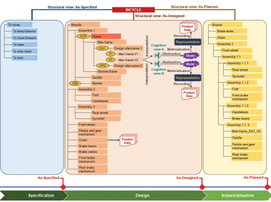
Figure 11 Multi-view product structure (see online version for colours)
Notes: N.B. We draw the reader’s attention to the fact that, in reality, in PLM tools, product data is bound to technical objects, as in the case for the ‘chain’. Nonetheless, we highlight the conceptual process that leads to the creation of product data, which is explicitly depicted on the ‘Men frame V2’ technical object.
2.8.2 Bill of materials
Although a BOM is often defined as the list of parts required to manufacture and assemble a product (IEC, 2003; ISO, 2009, 2010b; Saaksvuori and Immonen, 2008), it is more generally a listing of the things that make up an end item (Stark, 2011). For instance, software components that are required for the good functioning of a product must be considered during the assembly phase, in the same way as the purchased components that are on the list. A BOM can also include attributes such as the quantity, the materials, the cost, etc. According to the product complexity, the list can be flat (Saaksvuori and Immonen, 2008) or hierarchical (Stark, 2011). Additionally, unlike product structures, a BOM cannot store a complete customised products family; it only lists the technical objects for a given customised product (Svensson and Malmqvist, 2002). Design alternatives, versions, revisions and discarded potential options are not part of the BOM. Finally, a BOM does not consider the product data that is associated with the technical objects. A BOM can be seen as a filtered snapshot of a product structure at a given moment. Thus, during the product’s lifecycle, several BOMs generally exist with varying content (technical objects and attributes) for different purposes. The most well-known BOMs are the engineering bill of material (eBOM) and the manufacturing bill of material (mBOM), which respectively list a set of design objects to be industrialised, and a set of industrial objects required to be manufactured. The eBOM is exported from the as-designed structural view, whereas the mBOM is exported from the as-planned structural view.
Definition – BOM: a flat or hierarchical recap list of the technical objects that make up a customised product at a given moment.
2.9 Configuration and CM
In 2.6.1, we pointed out that a configuration and the process of CM are often assimilated to what we call a customised product and product diversity management, respectively. However, as described below, these concepts are not synonyms, strictly speaking.
2.9.1 Configuration
A configuration is a set of interrelated functional and physical characteristics of an existing or planned product (DoD USA, 2001; ISO, 2003a, 2011; NASA, 2008). The definitions given by Fiorèse and Meinadier (2012), ISO (2010b) and Watts (2012) are similar to what we call a customised product. It is true that each customised product is a set of interrelated functional and physical characteristics, and is thus a configuration. In addition to the variants and options, a configuration also includes the concept of version. Because the configuration of a product evolves throughout the product lifecycle (Svensson and Malmqvist, 2002), a configuration is thus one of a series of sequentially created variations of a product (NASA, 2008), which includes the technical objects and their associated product data. Furthermore, since a configuration is time-related, it is imperative to consider the various natures of the technical objects that make up the successive structural views of a multi-view product structure. For instance, the initial configuration considers the functions of the as-specified structural view, whereas the following configuration not only considers the functions, but also the design objects of the as-designed structural view. Therefore, a configuration can be seen as a particular state of the product structure at a given time t of the product lifecycle.
Definition – Configuration: state of a product structure at a given time t of the product lifecycle.
2.9.2 Configuration baseline
A configuration baseline is an agreed-upon configuration that serves as a reference for further activities (Dolezal, 2008; Fiorèse and Meinadier, 2012; ISO, 2003a, 2011). Additionally, the DoD USA (2001) and NASA (2008) state that a configuration baseline is a basis for managing change during the engineering change process. Finally, product baselines are closely linked to the project milestones that mark out the product lifecycle (ISO, 2011).
Definition – Configuration baseline: a formally-approved configuration at key milestones of the product lifecycle.
2.10 Configuration management
CM is a set of coordinated technical, organisational and administrative activities that establish and maintain control of a configuration by maintaining consistent records of its status and by monitoring, reporting and analysing changes throughout the product lifecycle (Debaecker, 2013; INCOSE, 2010; ISO, 2003a, 2011; Svensson and Malmqvist, 2002). During a project review, CM enables the team to verify that the existing or planned product complies with the specified requirements (DoD USA, 2001; ISO, 2010b). Thus, CM can be seen as an identification and management step-by-step process
that assures an up-to-date definition, or realisation, of a planned, or an existing, product (Fiorèse and Meinadier, 2012), and that tracks and manages past configurations (Eigner and Fehrenz, 2011).
Definition – CM: a set of interrelated activities that enables a company to manage the different configurations of a product structure.
2.11 Digital mock-up vs. virtual prototype 2.11.1 Mock-up
According to the ISO (2010b), a mock-up is a product itself that is meant to be thrown away after being used. It is a hardware or physical product (Dolezal, 2008) whose function is to show future shapes and required volumes to stakeholders (Chambolle, 1999). The literature review reveals two relevant characteristics of a mock-up. Firstly, the materials used to build a mock-up are not consistent with the ones that will be selected for the final product; they are traditionally low-priced and easy to shape (Chambolle, 1999). Secondly, a mock-up is not functional, it is an inert or static product (Chambolle, 1999; Lorisson, 2010) that does not take into account the product’s behaviour.
Definition – Mock-up: an experimental, static and hardware product that is used to show stakeholders some physical characteristics of the final product.
2.11.2 Prototype
In contrast to a mock-up, a prototype is dynamic – it takes some or all of the product’s functionalities into account by including its dynamic behaviour (Lorisson, 2010). In other words, a prototype performs one or several functions by transforming input fluxes of materials, energy, or information into output fluxes. Hence, while mock-ups are frequently used in upstream lifecycle phases to exhibit potential design solutions, prototypes are used in downstream lifecycle phases to test and approve product functionalities and performance levels before moving to the next phase (DoD USA, 1998).
Definition – Prototype: an experimental, dynamic hardware and/or software product that is used to show stakeholders some or all physical and functional characteristics of the final product.
2.11.3 Digital
The term digital corresponds to the data whose format consists of digits and to the processes and functional units that use these data (ISO, 1993). As Lorisson (2010) reports, the lifecycle of a product is ‘under numerical control’, which means that it requires an extensive use of IT hardware and software.
Definition – Digital: qualifies something whose processing in some way requires the use of IT hardware and software.
2.11.4 Virtual
A virtual technical object can be assimilated to a fictitious functional unit that mimics a real object (ISO, 1993). It is fictitious because it is intangible and can exist even if the real one is non-existent (Dolezal, 2008).
Definition – Virtual: something that does not exist as such, but that can be made visible by using appropriate digital tools and processes.
2.11.5 Digital mock-up
In the field of CAD, a digital mock-up (DMU) is sometimes reduced to the three-dimensional geometrical representation of a part or of an assembly of parts. A DMU is not only a three-dimensional geometrical representation, it is also the product structure (Gausemeier et al., 2011; Hirz et al., 2013) and the product metadata related to it (Dolezal, 2008). As a mock-up, a DMU is a static graphic representation that enables users to visualise and assess the future characteristics of the real product, such as its shapes (Guyot et al., 2007; Herlem et al., 2012; Kaun, 2002; Toche et al., 2012), space allocation (Guyot et al., 2007) and collisions (Guyot et al., 2007; Kahn, 2013; Kaun, 2002). A DMU is a basic unit to carry out a virtual simulation of the assembly and disassembly process (Hirz et al., 2013), and to detect the potential ergonomic constraints during the assembly/disassembly, maintenance and dismantling operations (Kaun, 2002). Lorisson (2010) differentiates a DMU from a virtual mock-up. The former is a database that contains the definition (mainly geometric) of a digital product, while the latter relates to a virtual environment in which a project team is setup, as in a classical physical mock up, to perform reviews and make decisions. Taraud and Glemarec (2008) report that a DMU cannot be limited to the three-dimensional picture of a product, but that it consists of the set of digital representations leading to the final design of a product. Kaun (2002) adds that a DMU is also used to manage product diversity and changes. As reported by von Praun (1998), a DMU serves as a platform for product and process development, communication and decision-making, from the first product concept all the way to after-sales service and recycling analysis. Although the literature provides us with an exhaustive list of characteristics that can be associated with a DMU, its definition remains fuzzy (Drieux, 2006). Therefore, we will look at various kinds of DMUs to identify the boundaries of the concept.
• Functional digital mock-up (FDMU) – a FDMU is unanimously considered as an extension of a DMU (Enge-Rosenblatt et al., 2011; Schneider et al., 2010; Stark et al., 2011). Product behavioural aspects (e.g., the kinematics and/or dynamics of multibody systems, hydraulics, control, etc.) are added to the three-dimensional geometrical representations of a classic DMU. Behavioural simulations are used to experiment and validate some of the expected product’s functions during the design phases (Enge-Rosenblatt et al., 2011; Fukuda et al., 2013; Hirz et al., 2013;
Schneider et al., 2010; Stark et al., 2011). FDMUs are key artefacts that enable engineers to integrate highly interactive heterogeneous components, such as those that make up multi-physical products (Schneider et al., 2010; Stark et al., 2011).
Figure 13 Functional digital mock-up (see online version for colours)
Definition – FDMU: the virtual geometrical and topological representation of the physical features of the planned product, integrating some of its behavioural aspects. • Virtual prototype – The term virtual prototype is either used to refer to a DMU
(Nguyen Van et al., 2006; Sibois, 2013; Stark et al., 2011), or to an FDMU (Gausemeier et al., 2011; Radkowski, 2011; Wang, 2003). Based on the previous definition of a prototype, we consider a virtual prototype as an FDMU.
• Model-based definition (MBD) – a MBD is the combination of a geometrical representation of a technical object with informative 3D annotations. The main application of MBD is the integration of geometric and tolerancing (GD&T)
information into the geometrical representation (Quintana et al., 2010). Thus, with an MBD there should be no need to manage the geometrical representation and its associated drawings (Quintana et al., 2010). An MBD can not only embed GD&T information, it also has the capacity to structure various types of information such as materials, version, ID, notes, etc. (Alemanni et al., 2011).
Definition – MBD: a virtual geometrical and topological representation of the physical features of a technical object that embeds informative 3D annotations. • Industrial digital mock-up (iDMU) – an iDMU is a DMU that integrates all the
product data that relates to a product, its processes and resources (Mas et al., 2013b; Menéndez et al., 2013). Thus, the functional design and the industrial design (manufacturing and assembly processes, technical and human resources) are merged into one single ‘DMU as a master’ that integrates most of the collaborative
engineering activities (Mas et al., 2013b, 2013c). One of the key advantages of an iDMU is its capacity to generate an as-built iDMU, that is, a complete definition and verification of the virtual manufacturing of a product, which takes into consideration the deviations from the industrialisation phase to the manufacturing phase (Mas et al., 2013b, 2013c).
Definition – iDMU: an integration of both design aspects, functional and industrial, which merges all the product data that relates to a product, the processes and the resources into a single DMU that is used as a master by all of the collaborative engineering activities.
Definition – DMU: virtual geometrical and topological representation of the physical features of a technical object with its associated product metadata, which can be enriched by further design details, such as behavioural aspects, informative
annotations and industrial processes. ADMU that allows simulating the behavioural aspects of the technical object is qualified as functional. A DMU that embeds informative 3D annotations is qualified as MBD. A DMU that integrates functional and industrial design aspects is qualified as industrial. Nevertheless, a DMU turns out to be a set of virtual artefacts that aims at unifying all these various types of information. Such a numerical database of virtual artefacts is the bedrock for a concurrent (simultaneous and integrated) engineering design strategy.
Figure 14 Model-based definition
Source: Quintana and al. (2010)
3 A conceptual map of ambiguous PLM terms used in discrete manufacturing
In Section 2, for each ambiguous PLM term used in discrete manufacturing, we have suggested one or several definitions according to whether they were referring to one or several concepts. Therefore, each term is now linked to a PLM concept whose characteristics are given by a definition.
Figure 15 A conceptual map of ambiguous PLM terms used in discrete manufacturing (see online
In this section, we provide a conceptual map of the clarified terms. The nodes of the graph are labelled with the terms referring to the refereed definitions, and the directed edges stand for the relations between a pair of terms. The blue nodes are concepts used in PLM that were initially considered ambiguous and which we have uniquely defined and labelled. The yellow nodes are key characteristics or instances that helped us to define and refine the general concepts. Finally, the green nodes symbolise terms that we have introduced, labelled and defined.
The conceptual map is a logical structure < Predicate, Subject, Object > – P(S, O). Such a formal description enhances the accuracy of the natural language definitions without requiring a specific theoretical background in logic in order to be understood. For instance, the conceptual mapping ‘EBOM – is a kind of –> BOM’ is similar to the logical triple ‘Is_A_Kind_Of(EBOM, BOM)’ and to the natural language sentence ‘An EBOM is a kind of BOM’. Thus, the whole mapping of terms shows the consistency among all terms that stand for the refereed definitions. Moreover, the graph representation gives a clear overview of how the concepts used in PLM relate to each other, which is very difficult to see if we only jump from one text-based definition to another.
Finally, although this is not the original intention, the conceptual map is another way to define PLM. Indeed, it gives an initial context – a boundary and the constituting concepts – for PLM. Of course, this is far from considering all of the concepts relating to PLM, but the map at least gives a first overview that is open to be discussed, modified and enriched.
4 Conclusions and further work
PLM vocabulary has been weakened by semantic ambiguities, which are due to the popularisation of PLM across numerous fields (e.g., aerospace, automotive and apparel design) and actors (e.g., academics and industrialists; software users and software providers). This paper identifies, discusses, defines and illustrates 32 ambiguous PLM terms used in discrete manufacturing so as to discern a unified glossary. Recurrent questions are discussed and evaluated, such as: Can a product be a software or a service? What distinguishes a variant from an option? Are a BOM and a product structure two identical concepts? What differentiates a model from a representation? What is a view? What are the boundaries of a digital-mock-up? Is there one single DMU or several? Etc.
Although this paper covers a fair part of the most ambiguous key PLM concepts, additional terms and definitions can be provided for concepts that have not been broached in our glossary, and which can also be used to enrich the conceptual map. Another improvement would be to extend the scope to the ambiguous PLM terms used in a continuous process.
Finally, the main objective of this paper is to draw the PLM community’s attention to the need for PLM standards that mandate official PLM keywords and definitions in order to ease the integration of people.
References
Agard, B. (2004) ‘Modélisation des familles de produits: État de l’art (Product family modelling: state of the art)’, Mécanique & Industries, in French, Vol. 6, No. 3, pp.275–288.
Alemanni, M., Destefanis, F. and Vezzetti, E. (2011) ‘Model-based definition design in the product lifecycle management scenario’, International Journal of Advanced Manufacturing
Technology, Vol. 52, Nos. 1–4, pp.1–14.
Brière-Côté, A., Rivest, L. and Desrochers, A. (2010) ‘Adaptive generic product structure modelling for design reuse in engineer-to-order products’, Computers in industry, Vol. 6, No. 1, pp.53–65.
Callahan, S. (2006) ‘Extended generic product structure: an information model for representing product families’, Journal of Computing and Information Science in Engineering, Vol. 6, No. 3, pp.263–275.
Chambolle, F. (1999) Un modèle produit piloté par les processus d’élaboration : application au
secteur automobile dans l’environnement STEP, Published PhD thesis, École Centrale Paris,
Paris, France, in French [online] http://www.plmlab.fr/uploads/documents/Frederic_ Chambolle_Memoire_These_Final.pdf (accessed 8 May 2014).
CIMdata (2014) CIMdata PLM Glossary [online] http://www.cimdata.com/en/resources/about-plm/cimdata-plm-glossary (accessed 8 May 2014).
Dassault Systèmes (2011) Getting Started with ENOVIA V6, User Guide V6R2011X, Companion
Learning Space, Dassault Systèmes.
Debaecker, D. (2013) Le projet PLM par l’expérience (The PLM Project by Experience), in French, Lavoisier, Paris.
Department of Defense United States of America (DoD USA) (1998) DoD Modeling and
Simulation (M&S) Glossary, MIL 5000.59-M, Department of Defense United Stated of
America [online] http://www.msco.mil/files/MSCO%20Online%20Library/DoD%205000.59-M%20-%20MS%20Glossary1%20-%2019980115.pdf (accessed 8 May 2014).
Department of Defense United States of America (DoD USA) (2001) Military Handbook.
Configuration Management Guidance, MIL-HDBK-61A(SE), Department of Defense United
States of America [online] https://acc.dau.mil/adl/en-US/142238/file/27622/MIL-HDBK-61A%28SE%29%20Configuration%20Management%20Guidance.pdf (accessed 8 May 2014).
Dolezal, R.W. (2008) Success Factors for Digital Mock-Ups (DMU) in Complex Aerospace
Product Development, Published PhD thesis, Technische Universität München, Institut für
Luft- und Raumfahrt (ILR), Lehrstuhl für Luftfahrttechnik, München, Germany [online] http://mediatum.ub.tum.de/doc/632972/document.pdf (accessed 8 May 2014).
Drieux, G. (2006) De la maquette numérique produit vers ses applications aval : proposition de
modèles et procédés associés (From the Digital Mock-Up of a Product towards its Downstream Applications: Suggestion of Associated Models and Process), Unpublished PhD
thesis, Institut National Polytechnique de Grenoble, Grenoble, France,(in French.
Ducellier, G. (2008) Gestion de règles expertes en ingénierie collaborative: application aux
plateformes PLM (Management of Expert Rules within Collaborative Design Context: Application to PLM Platforms), Unpublished PhD thesis, Université de Technologie de
Troyes, Troyes, France, in French.
Eigner, M. and Fehrenz, A. (2011) ‘Managing the product configuration throughout the lifecycle’, in Pels, H.J., Bouras, A. and McMahon, C. (Eds.): Product Lifecycle Management. Virtual
Product Lifecycles for Green Products and Services, 11–13 July, pp.396–405, Netherlands.
Electronic Industries Alliance (EIA) (1999) EIA 632:1999 Process for Engineering a System, Arlington.
ElMaraghy, H., Schuh, G., ElMaraghy, W., Piller, F., Schönsleben, P., Tseng, M. and Bernard, A. (2013) ‘Product variety management’, CIRP Annals – Manufacturing Technology, Vol. 62, No. 2, pp.629–652.
Enge-Rosenblatt, O., Clauß, C., Schneider, A. and Schneider, P. (2011) ‘Functional digital mock-up and the functional mock-up interface – two complementary approaches for a comprehensive investigation on heterogeneous systems’, in 8th International Modelica
Conference. Proceedings, Dresden, Germany, 20–22 March.
Erens, F-J. (1996) The Synthesis of Variety: Developing Product Families, Published PhD thesis, Eindhoven University of Technology, Eindhoven, Netherlands [online] http://alexandria.tue.nl/extra3/proefschrift/PRF12B/9603519.pdf (accessed 8 May 2014). Erens, F-J. and Verhulst, K. (1997) ‘Architectures for product families’, Computers in Industry,
Vol. 33, Nos. 2–3, pp.165–178.
Felfernig, A., Friedrich, G. and Jannach, D. (2001) ‘Conceptual modeling for configuration of mass-customizable products’, Artificial Intelligence in Engineering, Vol. 15, No. 2, pp.165–176.
Fiorèse, S. and Meinadier, J-P. (2012) Découvrir et comprendre l’ingénierie système (Introduction
in Systems Engineering), in French, Cédapuès, Toulouse, France.
Fukuda, S., Lulić, Y. and Stjepandić, J. (2013) ‘FDMU – functional spatial experience beyond DMU?’, in Bil, C., Mo, J. and Stjepandić (Eds.): 20th ISPE International Conference on
Concurrent Engineering: Proceedings, IOS Press, Melbourne, Australia, 2–6 September,
pp.435–444.
Garbade, R. and Dolezal, W.R. (2007) ‘DMU@Airbus – evolution of the digital mock-up (DMU) at Airbus to the central of aircraft development’, in Krause, F-L. (Ed.): The Future of Product
Development, Proceedings of the 17th CIRP Design Conference, Springer, pp.3–12.
Gausemeier, J., Berssenbrügge, J., Grafe, M., Sascha Kahl, K. and Wassmann, H. (2011) ‘Design and VR/AR-based testing of advanced mechatronic systems’, in Ma, D., Fan, X., Gausemeier, J. and Grafe, M. (Eds.): Virtual Reality & Augmented Reality in Industry. The
2nd Sino-German Workshop, Springer, Shanghai, China, 16–17 April, pp.1–37.
Grieves, M. (2005) Product Lifecycle Management: Driving the Next Generation of Lean Thinking, McGraw-Hill Education, USA.
Guyot, E., Ducellier, G., Eynard, B., Girard, P. and Gallet, T. (2007) ‘Product data and digital mock-up exchange based on PLM’, in Garetti, M., Terzi, S., Ball, P.D. and Han, S. (Eds.):
Product Lifecycle Management PLM’07. Assessing the Industrial Relevance, Chapter 4: Data Exchange, pp.235–242.
Herlem, G., Andragna, P-A., Ducellier, G. and Durupt, A. (2012) ‘DMU maturity management as an extension of the core product model’, in Rivest, L., Bouras, A. and Louhichi, B. (Eds.):
Product Lifecycle Management. Towards Knowledge-Rich Enterprises. IFIP Advances in Information and Communication Technology, Springer, 9–11 July, Vol. 388, pp.192–201,
Montreal, Canada.
Hirz, M., Dietrich, W., Gfrerrer, A. and Lang, J. (2013) Integrated Computer-Aided Design in
Automotive Development, Springer-Verlag, Berlin Heiderberg, Germany.
Hsiao, S-W., Ko, Y-C., Lo, C-H. and Chen, S-H. (2013) ‘An ISM, DEI, and ANP based approach for product family development’, Advanced Engineering Informatics, Vol. 27, No. 1, pp.131–148.
International Council on Systems Engineering (INCOSE) (2010) Systems Engineering Handbook
V. 3.2. A Guide for System Life Cycle Processes and Activities, INCOSE-TP-2003-002-03.2,
SE Handbook Working Group, International Council on Systems Engineering (INCOSE), January, San Diego, USA.
International Electrotechnical Commission (IEC) (2001) 82045-1:2001 Document management –
Part 1: Principles and Methods, Geneva.
International Electrotechnical Commission (IEC) (2003) IEC 62264-1:2003 Enterprise-Control
System Integration – Part 1: Models and Terminology, Geneva.
International Organization for Standardisation (ISO) (1993) ISO/IEC 2382:1993 Information
International Organization for Standardisation (ISO) (1994) ISO 10303-1:1994 Industrial
Automation Systems and Integration – Product Data Representation and Exchange – Part 1: Overview and Fundamental Principles, Geneva.
International Organization for Standardisation (ISO) (2003a) ISO 10007:2003 Quality Management
Systems – Guidelines for Configuration Management, Geneva.
International Organization for Standardisation (ISO) (2003b) ISO/TS 18876-2:2003 Industrial
Automation Systems and Integration – Integration of Industrial Data for Exchange, Access and Sharing – Part 2: Integration and Mapping Methodology, Geneva.
International Organization for Standardisation (ISO) (2004) ISO 15531-1:2004 Industrial
Automation Systems and Integration – Industrial Manufacturing Management Data – Part 1: General Overview, Geneva.
International Organization for Standardisation (ISO) (2005) ISO 9000:2005 Quality Management
Systems – Fundamentals and Vocabulary, Geneva.
International Organization for Standardisation (ISO) (2007) ISO 21349:2007 Space Systems –
Project Reviews, Geneva.
International Organization for Standardisation (ISO) (2008) ISO/IEC/IEEE 15288:2008 Systems
and Software Engineering – System Life Cycle Processes, Geneva.
International Organization for Standardisation (ISO) (2009) ISO 16100-1:2009 Industrial
Automation Systems and Integration – Manufacturing Software Capability Profiling for Interoperability – Part 1: Framework, Geneva.
International Organization for Standardisation (ISO) (2010a) ISO 10537:2010 Space Data and
Information Transfer Systems – Encapsulation Service, Geneva.
International Organization for Standardisation (ISO) (2010b) ISO/IEC/IEEE 24765:2010 Systems
and Software Engineering – Vocabulary, Geneva.
International Organization for Standardisation (ISO) (2011) ISO 10795:2011 Space Systems –
Programme Management and Quality – Vocabulary, Geneva.
Izadpanah, S-H., Gzara, L. and Tollenaere, M. (2009) ‘The mechanisms of construction of generic product configuration with the help of business object and delay differentiation’, in 19th CIRP
Design Conference – Competitive Design, Cranfield University, Cranfield, UK, 30–31 March,
p.134.
Jiao, J., Simpson, T.W. and Siddique, Z. (2007) ‘Product family design and platform-based product development: a state-of-the-art review’, Journal of Intelligent Manufacturing, Vol. 18, No. 1, pp.5–29.
Kahn, K.B. (2013) The PDMA Handbook of New Product Development, 3rd ed., Jowhn Wiley & Sons, Hoboken, New Jersey, USA.
Kaun, S. (2002) ‘The digital mock-up as a virtual working environment within the development process’, in RTO AVT Symposium on Reduction of Military Vehicle Acquisition Time and Cost
through Advanced Modelling and Virtual Simulation, Paris, France, 22–25 April.
Khedher, A.B., Henry, S. and Bouras, A. (2010) ‘An analysis of the interaction among design, industrialization and production’, International Conference on Product Lifecycle Management
(PLM10), Bremen, Germany, 12–14 July.
Kleiner, S. and Kramer, C. (2013) ‘Model based design with systems engineering based on RFLP using V6’, in Krause, F-L. (Ed.): Smart Product Engineering. Proceedings of the 23rd CIRP
Design Conference, Springer, Bochum, Germany, 11–13 March, pp.93–102.
Lorisson, J. (2010) ‘Réalité virtuelle dans l’industrie – Développement des produits et des processus (Virtual reality in industry – product and process development)’, Dossier techniques
de l’ingénieur l’expertise techniques et scientifique de reference, in French.
Männistö, T. (2000) A Conceptual Modelling Approach to Product Families and their Evolution, Published PhD thesis, Helsinki University of Technology, Helsinki, Finland [online] http://www.researchgate.net/publication/34773498_A_conceptual_modelling_approach_to_ product_families_and_their_evolution (accessed 8 May 2014).
Männistö, T., Peltonen, H., Soininen, T. and Sulonen, R. (2001) ‘Multiple abstraction levels in modelling product structures’, Data & Knowledge Engineering, Vol.36, No. 1, pp.55–78. Mas, F., Ríos, J., Menéndez, J.L. and Gómez, A. (2013a) ‘A process-oriented approach to modeling
the conceptual design of aircraft assembly lines’, The International Journal of Advanced
Manufacturing Technology, Vol. 67, Nos. 1–4, pp.771–784.
Mas, F., Menéndez, J.L., Oliva, M., Gómez, A. and Ríos, J. (2013b) ‘Collaborative engineering paradigm applied to the aerospace industry’, in Bernard, A., Rivest, L. and Dutta, D. (Eds.):
Product Lifecycle Management for Society. 10th IFIP 5.1 International Conference, PLM 2013, Springer, Nantes, France, 6–10 July, Vol. 409, pp.675–684.
Mas, F., Menéndez, J.L., Oliva, M. and Ríos, J. (2013c) ‘Collaborative engineering: an airbus case study’, Proceedings of the 5th Manufacturing Engineering Society International Conference, June, Zaragoza, Spain.
Maurino, M. (1994) La gestion des données techniques. Technologies du concurrent engineering
(Product Data Management. Concurrent Engineering Technologies), in French, Masson,
Paris, France.
Menéndez, J.L., Mas, F., Servan, J., Arista, R. and Ríos, J. (2013) ‘Implementation of the iDMU for an aerostructure industrialization in airbus’, The Manufacturing Engineering Society
International Conference, MESIC 2013, Vol. 63, pp.327–335.
Mtopi Fotso, B., Dulmet, M. and Bonjour, E. (2009) ‘Modélisation par les grammaires de graphes de la génération de la diversité dans les familles de produits (Using graph grammars for the generation of diversity in product family modelling)’, Journal Européen des systèmes
Automatisés, in French, Vol. 43, Nos. 1–2, pp.103–132.
National Aeronautics and Space Administration (NASA) (2007) NASA Systems Engineering
Handbook, NASA/SP-2007-6105 Rev1, December 2007, Washington, USA [online]
http://foiaelibrary.gsfc.nasa.gov/_assets/doclibBidder/tech_docs/5.%20NASA%20SP-6105%20Rev%201%20%28Sys%20Eng%20Handbook%29.pdf (accessed 8 May 2014). National Aeronautics and Space Administration (NASA) (2008) NASA Configuration Management
(CM) Standard, NASA-STD-0005, Washington, USA [online]
https://standards.nasa.gov/released/nasa/NASA_STD_0005.pdf (accessed 8 May 2014). Nguyen Van, T., Maille, B. and Yannou, B. (2006) ‘Digital mock-up – capabilities and
implementation on the PLM field’, in Bouras, A., Gurumoorthy, B. and Han, S. (Eds.):
International Conference on Product Lifecycle Management 2006, Bangalore, Karnataka,
India, 10–12 July, pp.165–175.
O’Donnell, F.J., MacCallum, K.J., Hogg, B. and Yu, B. (1996) ‘Product structuring in a small manufacturing enterprise’, Computers in Industry, Vol. 31, No. 3, pp.281–292.
Object Management Group (OMG) (2003) MDA Guide Version 1.0.1 [online] http://www.omg.org/cgi-bin/doc?omg/03-06-01 (accessed 8 May 2014). PLM Interest Group (2014) PLM Definition – Standard [online]
http://www.plmig.com/welcome/stdplmdefn.shtml (accessed 26 January 2014).
PLM Lab (2011) Une introduction à la gestion de configuration (Introduction to configuration
management), Version 1.3, in French, 22 March.
Puechoultres, B. (2013) Illustrated Glossary of PLM Terms, Unpublished document.
Quintana, V., Rivest, L., Pellerin, R., Venne, F. and Kheddouci, F. (2010) ‘Will model-based definition replace engineering drawings throughout the product lifecycle? A global perspective from aerospace industry’, Computers in Industry, Vol. 61, No. 5, pp.497–508.
Radkowski, R. (2011) ‘Towards semantic virtual prototypes for the automatic model combination’, in: Bernard, A. (Ed.): Global Product Development. Proceedings of the 20th CIRP Design
Conference, Springer, Nantes, France, 19–21 April, pp.307–318.
Randoing, J-M. (1995) Les SGDT (Product Data Management Systems), in French, Hermès-Lavoisier, Paris, France.