Science Arts & Métiers (SAM)
is an open access repository that collects the work of Arts et Métiers Institute of
Technology researchers and makes it freely available over the web where possible.
This is an author-deposited version published in:
https://sam.ensam.eu
Handle ID: .
http://hdl.handle.net/10985/10270
To cite this version :
Romain PIQUARD, Alain D'ACUNTO, Daniel DUDZINSKI - Study of burr formation and phase
transformation during micro-milling of NiTi alloys - In: 11th International Conference on High
Speed Machining, République tchèque, 2014-09-11 - Proceedings of the 11th International
Conference on High Speed Machining - 2014
Any correspondence concerning this service should be sent to the repository
Administrator :
archiveouverte@ensam.eu
Science Arts & Métiers (SAM)
is an open access repository that collects the work of Arts et Métiers ParisTech
researchers and makes it freely available over the web where possible.
This is an author-deposited version published in:
http://sam.ensam.eu
Handle ID: .
http://hdl.handle.net/null
To cite this version :
Romain PIQUARD, Alain DACUNTO, Daniel DUDZINSKI - Study of burr formation and phase
transformation during micro-milling of NiTi alloys - In: 11th International Conference on High
Speed Machining, République tchèque, 2014-09-11 - Proceedings of the 11th International
Conference on High Speed Machining - 2014
Any correspondence concerning this service should be sent to the repository
Administrator :
archiveouverte@ensam.eu
STUDY OF BURR FORMATION AND PHASE TRANSFORMATION
DURING MICRO-MILLING OF NITI ALLOYS
R. Piquard1, A. D’Acunto1, D. Dudzinski1*
1 LEM3 UMR CNRS 7239, 4, rue Augustin Fresnel, 57070 Metz, FRANCE
*Corresponding author; e-mail: daniel.dudzinski@univ-lorraine.fr
Abstract
Micro-milling can be defined as milling with end mills smaller than 1 mm of diameter. The top-down approach from milling to micro-milling is often used to define cutting conditions. Unfortunately geometries either for the active part or the overall shape are quite different from conventional tools, leading to inexistent problems at the macro-scale, such as a larger cutting edge radius to uncut chip thickness ratio leading to ploughing effect. Moreover, micro-milling can be used on particular material such as shape memory alloys in biomedical domain which are difficult to machine.
This study focuses on burr formation during shoulder milling for two biocompatible NiTi alloys: a martensitic NiTi (shape memory effect) and an austenitic one (pseudo-elasticity effect). Design of experiment is used to highlight the influence of various parameters (cutting parameters and material phases) on the burr formation in micro-milling NiTi alloys. Burrs were observed and measured using confocal, optical and electronic microscopy and tend to be as large as shoulders dimensions. Material phase transformation was also examined.
Analysis of variance emphasizes that the larger the feed per tooth and the smaller the width of cut are, the smaller the top burr is. Cutting strategy leads to different burr shape: up-milling burrs have a large curvature, whereas down-milling burrs are slightly bent. An affected layer of about 10 µm has been observed for the austenitic NiTi. The proposed experimental approach give the opportunity to study burr formation in micro-milling, the machinability of alloys or superelastic NiTi shape memory and a qualitative explanation of burr formation has been developed.
Keywords:
Burr formation; micro-milling; nickel-titanium alloys; design of experiments
1 INTRODUCTION
The Nickel-Titanium (NiTi) alloys are shape memory alloys (SMA) which exhibit two properties, pseudoelasticity and shape memory effect. Additional advantages such as biocompatibility, good fatigue and corrosion resistance, high damping capacities [Wu 1999] allow NiTi alloys to be used in medical, dental and micro-mechanics applications. The high ductility, the high degree of strain hardening of NiTi alloys, their unconventional strain-stress behaviour lead them to be difficult to process, more particularly difficult to machine by using conventional techniques The machinability of TiNi shape memory alloys was examined with turning and drilling experiments by Weinert and Petzoldt [Weinert 2004a,b]. The turning tests concerned a NiTi alloy, they were performed under dry and wet conditions for various cutting speed values. According to their experimental results, the authors proposed to distinguish three stages to describe the machinability of this alloy. At low cutting speeds (Vc ≤ 60
m/min), the cutting forces were very high and as a consequence the tool wear was elevated with a high notch wear. Using emulsion as lubricant reduced cutting forces
and tool wear only for cutting speed values lower than 20m/min. In the second stage (60 ≤ Vc ≤ 130 m/min), the
cutting forces and the tool wear appeared to be unaffected by the cutting speed value and by the cutting fluid. In the third range (VC >130m/min), the cutting forces and the tool wear increased significantly for dry conditions. Due to its high ductility another problem, burr formation, occurs during TiNi alloys machining. The burrs may be characterized by their height hb and width wb. At the
beginning of the cutting process, the width of the burr is less than the feed rate and then it increases rapidly to attain higher values. In the same way, the height of burr may grow up to several millimetres. The recommendations were to use emulsion, to choose favourable cutting speed value of about 90-100m/min, to avoid small feed rates and to prefer larger cutting depths. They found that the better feed values are between 0.04 and 0.09 mm/rev, and that the cutting depth should be limited to the tool corner radius. When the cutting depth exceeded the tool corner radius high notch wear occurred. It must be noted that a poor chip breaking is an additional problem for NiTi alloy turning. After turning tests, drilling and deep drilling were performed. Depending on cutting speed and feed rate
chosen high enough, these processes caused an increase of the micro-hardness in the machined subsurface due to work hardening.
As it was pointed out previously, the NiTi alloys may be used to product micro-parts for medical applications or micro-actuators. With this objective, NiTi micro-milling was examined by Weinert and Petzoldt [Weinert 2008]. The cutting tools were solid carbide end mills with a diameter of 0.4mm; all the tools were coated with a TiAlN layer. The machining tests were performed both under dry and wet conditions. It was demonstrated that in comparison to dry machining, MQL reduced the NiTi-adhesions and the flank wear on the end-mills. Under MQL, high surface quality was obtained; however large burr formation was observed. The burr formation can be reduced by increasing radial engagement and depth of cut ap. The best results were
finally obtained under MQL by choosing Vc = 33 m/min, fz
= 12 µm, ae = 40 µm, ap = 10 µm; and different structures
were machined with success using these conditions. The definition but also the description of the burrs are not unique, and depends on several conditions. In this study, a burr was considered as an accumulation of material on the edges of a workpiece.
According to Gillespie [Gillespie 1999], three different mechanisms of burr formation can occur:
Poisson burr: the material is bulged on the free surfaces, due to high compression and plastic deformation.
Tear Burr: comes from the removal of the chip on the piece, similar to punching burrs.
Rollover Burr: due to bending of the material, often the last chip on the exit surfaces which is still attached.
These mechanisms do not necessarily occur on all edges of the workpiece. A classification of burrs depending on their location in slot milling was presented by [Aurich 2009] and is presented on Fig. 1.
Hashimura et al. [Hashimura 1995] compared burr formation of side burr and exit burr in oblique cutting of aluminium alloy by FEM and experiment. As a result, the larger the angle of inclination was, the larger the side burr was. Exit edge break out would not occur with large inclination angles due to the smaller strain of oblique cutting compared to orthogonal cutting.
Lekkala et al. [Lekkala 2011] presented a study on burr formation in micro-milling of slots using the method of design of experiments and Analysis of Variance. They found that burr height was influenced by tool diameter, axial engagement, number of teeth and feed rate. An increase in feed rate tended to decrease the height of burrs. In up-milling, burrs seemed torn. Finally, the author proposed an analytical modelling (physical and geometrical) of the height of exit burrs based on the continuity of the mechanical work and presents results in agreement with experimental results with an accuracy between 0.65 and 25%.
Weinert and Petzoldt [Weinert 2004b] proposed a qualitative model of burr formation in turning operations, the geometry of top burrs was defined by two parameters, the height and width of burr (respectively hb and wb). Two
stages were presented. For the first one, the width of the burr was smaller than the feed, conducting to a full removal of burr at each rotation. For the second stage, the width of burr was larger than feed, conducting to a partial removal of burr at each workpiece rotation and adding a burr growth by bulging of material. In turning operation the
change from stage 1 to stage 2 was due to an increase of tool wear.
Fig 1: Burr location in slot milling [Aurich, 2009]
2 EXPERIMENTAL
SET-UP
2.1 Materials
The two machined materials were a martensitic and an austenitic NiTi. The unique properties of NiTi are due to a phase transformation between austenitic and martensitic phases. This transformation occurs at definite conditions of stress load and temperature and can be initiated during machining.
Four characteristic temperatures related to this phase transformation are used to define this material. At a zero-stress state, and under a temperature load, the start temperature and finish temperature of martensite transformation are known as Ms and Mf and the start
temperature and finish temperature of the reverse transformation are As and Af. These temperatures were
identified by Differential Scanning Calorimeter (DSC) and are given in Tab. 1.
Tab 1: Characteristic temperatures of the two materials
Material phase Ms (°C) Mf (°C) As (°C) Af (°C)
Martensitic 40.3 15.4 59 84.5 Austenitic -53 -79 -30.1 undefined
2.2 Set-up
Milling tests were performed on a Röders RXP 200DS CNC (3,000 - 60,000 rpm) 5-axis high speed machining center (Fig. 2). The experiments were conducted with minimum quantity lubrication (MQL). Tools used were referenced by NS TOOL as MX 225 with a diameter of 0.8 mm, two teeth, a helix angle of 25° and a MUGEN coating. Both cutting edge radius and corner radius had been measured and were respectively about 3 µm and 6 µm. The machining procedure followed these steps:
The specimen was surfaced after a spindle warm-up of 30 min to get the upper plane (reference for the depth of cut) with an end mill (Hitachi HYPS 2020) with a diameter of 2 mm, by sweeping along the Y axis of the machine tool. Before machining, the tool was measured by the laser system of the CNC. Slots were machined along the Y axis with a cutting
diameter of 0.8 mm (full diameter engagement) and a depth of 200 µm by step of 10 µm.
After another warm-up of 30 minutes, the tests were performed on the side of the previous slots (shouldering), with the cutting conditions proposed in
the design of experiments and another warm-up was set when the cutting speed changed.
Warm-up led to control the depth of cut, tool measurement being the only source of dimensional error (spindle warm-up minimizing the thermal expansion).
In order to minimize the tool wear influence on burr formation, a tool should mill 4 square shoulders. In the same way, MQL use was justified [Weinert 2008].
Fig. 2: RXP 200DS
Design of experiments approach (DOE) was justified by the small number of experiments, the measurement duration of responses being relatively long. Results were analysed based on Analysis of Variance (ANOVA) and Fischer-Snedecor test for a significance level of 95%. In order to find the appropriate array and to analyse rapidly the results, the software Nemrodw® was used. In this DOE, burr height hb, width wb and thickness tb had been
used as responses (output variables).
The main interests in the study were the machining conditions and material. Depth of cut ap, width of cut ae,
cutting speed Vc, feed per tooth fz, strategy (up and
down-milling) and material phase were the studied factors. The levels of these independent parameters (input variables) are recapitulated in Tab. 2 and had been selected to cover a range around Weinert and Petzoldt [Weinert 2008] recommended parameters.
Tab.2: Levels of parameters
Parameter Low level High level
NiTi material Austenitic Martensitic
Strategy Up-milling Down-milling
Cutting speed (m/min) 30 60
Feed per tooth (µm) 6 12
Depth of cut (µm) 50 100
Width of cut (µm) 100 200
A linear behaviour was considered, which involved 2 levels for each parameter. In addition, 6 interactions were considered:
Material and cutting speed, Material and depth of cut, Material and feed per tooth, Feed per tooth and width of cut, Strategy and width of cut,
Cutting speed, depth of cut and feed per tooth.
These interactions might be influent on burrs formation, due to the dependency of the cutting conditions on material (for the first three interactions), to the cross
section of uncut chip (for the fourth one) and to dynamic of the cutting process as cutting forces variation and chip flow rate (for the last interactions). Thus the model considered can be written as in equation (1).
∑ . ∑, (1)
, ,
Where is the theoretical response, is the average, the vector associated to a parameter which equals to 1
0 when the parameter is at the lowest level and to 0
1 when it is at the highest level, is the effect of the parameter (the sign giving the level), and are the effect of interactions.
A 26-2 array (16 experiments), with 1 repetition for a total of 32 experiments had been chosen in order to improve the level of confidence with a limited number of experiments.
In order to measure burrs the most correctly, location of burrs had been completed for this study. 12 locations had been denominated, shown on Fig. 3, burrs from 1 to 6 obtained in up-milling, from 7 to 12 obtained in down-milling. Top burr, entrance burr, entrance side burr, exit burr and exit side burr still exist and a burr that can be called tip burr was added which can be related to exit burr for cutting direction according to Olvera and Barrow [Olvera 1996]. This burr is created by the tip of the end-mill on the lowest edge of the square shoulder.
Fig. 3: Used burr locations
Concerning burr measurements, three dimensions were considered to define them: height, width and thickness of burrs as shown on Fig. 4. Average height was measured using a white light confocal interferometer (Leica DCM3D). Width was measured using SEM (Jeol JSM-7001F) and thickness using an optical microscope (Zeiss Axio Imager M1m) after polishing entrance surface. Height and width could also be measured with optical microscope, but these values were representative of a specific section; with the two other measurement systems, an average dimension could be found on the biggest burrs along the square
shoulder as the burrs dimensions presented a large variation.
Fig. 4: Top burr dimensions
3 RESULTS AND DISCUSSION
3.1 Preliminary results
Fig. 5 highlights location and size of the different burrs. It can be noted that the largest burrs are 4, 5, 8 and 10 from Fig. 2. Top burrs obtained in up-milling (4) present a large curvature, whereas top burrs obtained in down-milling (10) are lightly bend. Moreover, top burrs obtained in up-milling are torn along the edge, and respectively these obtained in down-milling are continuous with cracks on the top. From these preliminary observations, the parameters of DOE affect only the top burrs whereas the exit side burrs (5 and 11) and entrance side burrs (2 and 8) which are only dependent of strategy. That is the reason why only top burrs are studied in the DOE.
Fig. 5: Observable burrs (tests n°3 and 4)
SEM observations of end-mills ensure that tool wear is negligible with an EDS analysis. The dimensions of wear zone where the tungsten can be detected are about 100µm along the cutting edge and a width of approximately 10µm corresponding to the upper levels of depth of cut and feed per tooth. Nickel and titanium elements are present on the cutting edge, representative of alloy deposit on the tool.
3.2 Design of Experiments results
Regarding burrs, results of the ANOVA for burr dimensions (hb, wb and tb) show that the model is valid at
99% confident. It means that this model is sufficient to describe the phenomenon of burr formation.
For the height of burr hb, the results of ANOVA are
presented in Tab. 3. Three parameters are influent, the height, the width of cut and the feed per tooth, and four interactions: between cutting speed and material, between depth of cut and material, between feed per tooth fz and
width of cut ae, and between ae and the strategy.
Moreover, more than 60% of the total effects of significant factors are represented only by the effects of feed per tooth fz, width of cut ae and their interaction. An increase of
depth of cut and feed per tooth implies a decrease of burr height of respectively 7.44µm and 29.06 µm, whereas an increase of width of cut implies an increase of burr height of 18.94µm. The interaction means that the positive effect of width of cut (increase of the height of burr) is greater when feed per tooth fz is equal to 6 µm than for a value of
12 µm.
Tab. 3: ANOVA for height of top burrs ANOVA : Height of burrs hb Average value : hb= 63.34 µm
Parameters Effect value Significance at 95% P (%)
Strategy -0.22 No 88.3 ap -3.72 Yes 2.17 * Vc -1.66 No 27.4 Matérial 0.03 No 98.3 fz -14.53 Yes < 0.01 *** ae 9.47 Yes < 0.01 *** Vc x Material -4.22 Yes 1.08 * Material x fz 1.41 No 35.1 ap x material -3.53 Yes 2.81 * ap x Vc x fz 0.66 No 66 fz x ae -5.66 Yes 0.137 ** Strategy x ae 4.03 Yes 1.41 *
*: significance from 95% to 99%; **: significance from 99% to 99,9%; ***: significance over 99,9%
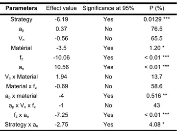
For the width of burrs wb, the results of ANOVA are
presented in Tab. 4. The effects of feed per tooth fz and ae
represent almost 50% of total effects. An increase of feed per tooth implies a decrease of burr height of 20.12 µm, whereas an increase of width of cut implies an increase of burr height of 21.12 µm. The interaction between feed per tooth fz and width of cut ae is also highly influential and its
effect on the same trend as the height of burrs. The effect of machining strategy (largest burrs are obtained in up-milling) confirms the preliminary observations on the shape of top burrs. Larger burrs are obtained in austenitic phase than in martensitic phase.
Tab. 4: ANOVA for width of top burrs ANOVA : Width of burrs wb Average value : wb= 65.87 µm
Parameters Effect value Significance at 95% P (%)
Strategy -6.19 Yes 0.0129 *** ap 0.37 No 76.5 Vc -0.56 No 65.5 Matérial -3.5 Yes 1.20 * fz -10.06 Yes < 0.01 *** ae 10.56 Yes < 0.01 *** Vc x Material 1.94 No 13.7 Material x fz -0.69 No 58.6 ap x material -4 Yes 0.516 ** ap x Vc x fz -1 No 43 fz x ae -7.25 Yes < 0.01 *** Strategy x ae -2.75 Yes 4.08 *
*: significance from 95% to 99%; **: significance from 99% to 99,9%; ***: significance over 99,9%
Regarding the thickness of the burrs tb, the results of
ANOVA are presented in Tab. 5. All factors have a significant effect and only the interaction between the machining and width of cut ae is considered influential.
The most influential factor is the machining strategy. Burrs obtained by down-milling are thicker of 4.44 µm than those obtained by up-milling. An increase of the cutting speed also tends to get thicker burrs of 3.44 µm, contrary to the effect of the depth of cut ap, feed per tooth fz and width of
cut ae.
Tab. 5: ANOVA for thickness of top burrs ANOVA : Thickness of burrs tb
Average value : tb= 7.22 µm
Parameters Effect value Significance at 95% P (%)
Strategy 2.22 Yes < 0.01 *** ap -0.84 Yes 0.0806 *** Vc 1.47 Yes < 0.01 *** Matérial 1.72 Yes < 0.01 *** fz -0.72 Yes 0.292 ** ae -0.97 Yes 0.0228 *** Vc x Material 0.34 No 11.3 Material x fz 0.41 No 6.5 ap x material -0.34 No 11.3 ap x Vc x fz -0.16 No 45.7 fz x ae -0.41 No 6.5 Strategy x ae -0.84 Yes 0.0806 ***
*: significance from 95% to 99%; **: significance from 99% to 99,9%; ***: significance over 99,9%
The interaction between strategy and depth of cut shows that an increase of width of cut ae in up-milling doesn’t
affect burr thickness, unlike in down-milling where the effect of an increase of width of cut ae tends to a
significant decrease of burr thickness.
Considering the modelling given in equation (1) and only the significant parameters, the burr dimensions can be written as in equation (2), (3) and (4).
63.34 3.72 3.72 . 14.53 14.53 . 9.47 9.47 . 4.224.22 4.224.22 3.53 3.53 3.53 3.53 5.66 5.66 5.66 5.66 4.03 4.03 4.03 4.03
(2)
65.87 6.19 6.19 . 3.5 3.5 . 10.06 10.06 . 10.56 10.56 . 44 44 7.25 7.25 7.25 7.25 2.752.75 2.752.75(3)
7.22 2.22 2.22 . 0.84 0.84 . 1.47 1.47 . 1.72 1.72 . 0.72 0.72 . 0.97 0.97 . 0.84 0.84 0.84 0.84(4)
This modelling allows to find the conditions in order to obtain the smallest burrs according to measured dimensions. In order to give equal weight in the minimization process to the three dimensions, it has been decided to multiply thickness by 10. Thus optimal cutting conditions are for both martensitic and austenitic NiTi, a cutting speed of 30 m/min, a feed per tooth of 12 µm, a width of cut of 100 µm and an up-milling strategy.
Concerning depth of cut, 50 µm are preconized for Austenite and 100 µm for martensite.
3.3 Phase transformation
Phase transformation has been observed through micrographs of the cross section of the two samples after machining. Concerning the austenitic NiTi, no modification of the microstructure is observed. Nevertheless, some martensitic needles are visible throughout the thickness of the sample as a result of a large plastic deformation, probably due to the initial forming process. Concerning the martensitic NiTi, a zone of approximately 20 µm under the machined surface has been affected by a phase transformation. Austenitic phase appears probably due to heating and no return to martensitic state occurred.
3.4 Burr formation process
Streaks on top burrs can be observed: this is similar to segmentation of formation of shear bands on chips. However, the discontinuity of milling process suggests that these streaks come from the successive passing of teeth. In addition, streaks are similar to marks let by the tool tip path.
Fig. 6: explanation of top burr streaks formation
One possible explanation is shown in Fig. 6; a burr is formed on the curved free edge by the flank cutting edge. This burr is bulged material due to high compressive stress for small uncut chip thickness, and increased due to the helix angle leading to an oblique cutting. By the accumulation of small burrs for each tool passage (each semi-rotation), a bigger one appears.
Regarding the results of DOE, the strong dependence of the width and height of burrs to width of cut ae and feed
per tooth fz fits with the explanation previously developed
for top burr formation. Indeed, an increase of width of cut implies an increase of top burr height; in addition, the length of the burr formed by bulging is a function of the length of contact between material and tooth, thus to width of cut; as a consequence the height of burr is a function of width of cut. Concerning the effect of feed per tooth fz,
which tends to a decrease in the height of burrs for an increase of this parameter, it is explained by the fact that for a greater feed, at each passage of the tooth, a larger part of burr created by the preceding tooth is deleted. This effect was explained by Weinert [Weinert 2004b] for turning operations.
The interaction between fz and ae, having a significant
effect on height and width of burrs, confirms this possible explanation. An increase of feed per tooth fz causes a
decrease in the effect of width of cut ae; it is possible that
for a large feed, the burr generated by a tooth is removed partially by the next tooth.
4 CONCLUSION
NiTi is mostly used in biomedical field and for this reason burrs have to be minimized. Thanks to burr dimensions proposed in this work, significant parameters for burr formation have been identified through experiments using Design of Experiments. In order to minimize burr dimensions, recommended parameters are a large feed per tooth and a small radial engagement leading to smaller height and width of top burrs. Moreover a down-milling strategy and a low cutting speed permit to have thinner burrs for an easier deburring.
In a same way, burr minimization can have an impact on machining process layout. In such a case, it is preferable to machine shoulder parts before machining the upper plane. In this case tip burrs are created instead of top [Aurich 2009].
Design of Experiments gives quantitative results on burr formation in the range of considered cutting conditions but cannot give a complete modelling of burr formation. Some modelling can predict exit side burr dimensions by analogy with orthogonal cutting. In order to model top burr
formation, a complete 3D cutting modelling of micro-milling is necessary with a characteristic mesh length close to the cutting edge radius which can be time consuming.
5 REFERENCES
[Aurich 2009] Aurich, J.C., Dornfeld, D., Arrazola, P.J., Franke, V., Leitz, L. and Min, S., Burrs—Analysis, control and removal. CIRP Annals - Manufacturing Technology. 2009. Vol. 58, n° 2, pp. 519‑542. DOI 10.1016/j.cirp.2009.09.004.
[Gillespie 1999] Gillespie, L.K., Deburring and edge finishing handbook. 1999. SME. ISBN 0872635015. [Hashimura 1995] Hashimura, M., Ueda, K., Dornfeld, D., and Manabe, K., Analysis of three-dimensional burr formation in oblique cutting. CIRP Annals-Manufacturing Technology, 1995, Vol. 44(1), pp. 27-30.
[Lekkala 2011] Lekkala, R., Bajpai, V., Singh, R.K. and Joshi, S.S., Characterization and modeling of burr formation in micro-end milling. Precision Engineering-Journal of the International Societies for Precision Engineering and Nanotechnology. 2011. Vol. 35, n° 4, pp. 625‑637. DOI 10.1016/j.precisioneng.2011.04.007. WOS:000294239500009.
[Olvera 1996] Olvera, O. and Barrow, G., An experimental study of burr formation in square shoulder face milling. International Journal of Machine Tools and Manufacture. 1996. Vol. 36, n° 9, pp. 1005–1020.
[Weinert 2004a] Weinert, K., Petzoldt, V. and Kötter, D., Turning and drilling of NiTi shape memory alloys. CIRP Annals-Manufacturing Technology. 2004. Vol. 53, n° 1, pp. 65–68.
[Weinert 2004b] Weinert, K. and Petzoldt, V., Machining of NiTi based shape memory alloys. Materials Science and Engineering: A. 2004. Vol. 378, n° 1, pp. 180–184. [Weinert 2008] Weinert, K. and Petzoldt, V., Machining NiTi micro-parts by micro-milling. Materials Science and Engineering: A. 2008. Vol. 481, pp. 672–675.
[Wu 1999] Wu, S.K, Lin, H.C et Chen, C.C,. A study on the machinability of a Ti49.6Ni50.4 shape memory alloy. Materials Letters. 1999. Vol. 40, n° 1, pp. 27‑32. DOI 10.1016/S0167-577X(99)00044-0.
![Fig 1: Burr location in slot milling [Aurich, 2009]](https://thumb-eu.123doks.com/thumbv2/123doknet/7433018.219976/4.892.512.742.131.376/fig-burr-location-slot-milling-aurich.webp)