HAL Id: hal-00663233
https://hal.archives-ouvertes.fr/hal-00663233
Submitted on 26 Jan 2012
HAL is a multi-disciplinary open access archive for the deposit and dissemination of sci-entific research documents, whether they are pub-lished or not. The documents may come from teaching and research institutions in France or abroad, or from public or private research centers.
L’archive ouverte pluridisciplinaire HAL, est destinée au dépôt et à la diffusion de documents scientifiques de niveau recherche, publiés ou non, émanant des établissements d’enseignement et de recherche français ou étrangers, des laboratoires publics ou privés.
Static analysis of sandwich plates by finite elements
Vincent Manet, Han Woo-Suck, Vautrin Alain
To cite this version:
Vincent Manet, Han Woo-Suck, Vautrin Alain. Static analysis of sandwich plates by finite elements. Euromech 360, May 1997, Saint-Etienne, France. pp.53-60. �hal-00663233�
BY FINITE ELEMENTS
V. MANET, W.-S. HAN AND A. VAUTRIN
´
Ecole des Mines de Saint-Etienne
Materials and Mechanical Engineering Department 158, cours Fauriel
42023 Saint-Etienne Cedex 2
Notations
{ } vector (column)
h i transposed vector (row) [ ] matrix
Ω element’s interior (volume or surface)
Γ element’s boundary (surface or curve)
Γ = ∂Ω = Γu∪Γσ; Γu∩Γσ = ∅
Γu part of Γ with prescribed
dis-placements
Γσ part of Γ with imposed forces
ΓI interface
U (small) displacements σ Cauchy’s stresses ε (small) strains λ Lagrange multipliers Dijkl Hooke’s operator
{σ} = [D] {ε} Sijkl [S] = [D]−1
[L] differential operator {ε} = [L] {U }
fΩ applied body forces in Ω T applied forces on Γσ
U prescribed displacements on Γu
1. Introduction
Sandwich plates being more and more involved in structural components, it becomes essential to develop analysis tools taking their specificities into account.
In this paper, we present some computational methods developed in order to describe the mechanical behaviour of sandwich plates in a more realistic way. Emphasis has been put on the determination of stresses at
2 V. MANET ET AL.
the interfaces between the skins and the core which have in general very heterogeneous mechanical properties.
A sandwich plate is a 3-layer laminate, whose layers have very differ-ent mechanical properties: the skins are generally very stiff and work in membrane, whereas the core, which has low stiffness and density, is sub-jected to shear efforts. It yields quite particular behaviour and failure modes (crack modes, instability modes, local denting...), as explained in (Teti and Caprino, 1989).
The main points of our sandwich modelling are the following:
− transverse shear effects are taken into account: this point is extremely important since the core is only subjected to shear loading;
− the continuity of displacements and the equilibrium state of stresses at each interface of layers are fulfilled: these conditions ensure the physical interface condition;
− large differences of the geometrical and mechanical properties between layers are correctly modelized;
− the relative magnitudes of stresses: the plane stress assumption used in the classical theory of laminated plates is not acceptable for sandwich plates.
Computation of stresses at interfaces is of particular importance for sandwich panels submitted to flexural bending. Nevertheless, it remains difficult to calculate these quantities in a accurate way: at the interfaces, only some components of stresses are continuous. We also face the problem of working with “reduced” stress fields (“reduced” means “which does not contain all the components”). For this purpose several approaches have been developed and are presented in this paper.
2. Hybrid sandwich finite elements
In this section, we present the development of different special finite ele-ments taking the aforementioned points into account.
Classical finite elements in displacements yield a correct displacement field, but cannot fulfill the equilibrium state of stresses, which are derived from displacements. On the other hand, mixed formulations, such as Reiss-ner’s one, which use both displacement and stress fields as variables, lead to the continuity of all components of both fields: these models induce too high number of degrees of freedom and non-required continuities.
Therefore, it is necessary to develop methods leading to the continuity of only required components. For this purpose, we introduced a reduced stress field as unknown. It can be done by insuring the displacements continuity at
the interfaces by Lagrange multipliers; these multipliers are easily identified as the reduced stress field. The developed hybrid sandwich elements are initially composed of three sub-elements through the thickness, exactly as a sandwich plate. The displacement field is interpolated quadratically in each layer to take flexural effects into account in a better way.
Ω1 Ω2 Ω3 ←− Γ1 I ←− Γ2I - 1 6 2 Ω1 Ω2 Ω3 ←− Γ1I ←− Γ2 I b b b b b b b b b b b b b b b b b b b b r r r r r r b Displacements r Lagrange multipliers
a) Sub-domains b) sandwich finite element
Figure 1. Sub-domains and finite element
We developed two families of hybrid sandwich elements. In the first type, we use the functional of the potential energy in each sub-layer and ensure the displacement continuity at interfaces with Lagrange multipliers repre-senting the reduced stress field. In the second case, we use the condensed Pian and Tong functional in each sub-domain and Lagrange multipliers to ensure the displacements continuity. These functionnals can be found in (Washizu, 1982).
The first hybrid sandwich element leads to a non-symmetrical and non definite-positive stiffness matrix, the second one to a symmetrical but non definite-positive stiffness matrix, which is typical of mixed systems. Vari-ational principles used by these elements are given in (Manet and Han, 1997).
We use the term “hybrid” because the displacement field in approxi-mated in the volume and Lagrange multipliers only along interfaces. We do not use the term “mixed hybrid” even if we have two types of unknowns (displacements and Lagrange multipliers) to point out that Lagrange mul-tipliers are not a physical field (although they have a physical meaning).
4 V. MANET ET AL.
3. Post-processing
Specials finite elements lead to “non-usual” stiffness matrices, in particular non definite-positive matrices. So, their implementation in commercialized FEM softwares is sometimes difficult.
3.1. STRESS PROJECTION
As an alternative solution, we developed a “stress-projection” method in order to improve the results obtained by displacement finite elements.
This method, initially proposed by (Zienkiewicz and Taylor, 1994), per-mits to improve the accuracy of nodal stresses extrapolated from stresses derived from the displacements at Gauss points.
The principle of the method is to minimize the difference between the stresses obtained from displacements and the stresses issued from a mixed formulation, in each element.
For sandwich structures, problems arise from the high heterogeneity of mechanical properties between the skins and the core. The computation of stresses at the interfaces cannot be done so easily, otherwise stresses would not fulfill the equilibrium state. We use the stress projection method, not on one element, but on two elements on each side of an interface, so that the integration volume includes the interface. In such a case, the calculated stress field fulfills the equilibrium state.
In the displacements formulation, stresses are obtained from nodal dis-placements {q} by: {σu} = [D] [L] [Nu] {q}, where [D] is the generalized
Hooke’s matrix and [Nu] the matrix of shape functions. In a mixed
formu-lation, stresses are obtained directly from nodal stresses {τ } by: {σm} =
[Nσ] {τ }. If we now minimize the differenceRΩ{σm}−{σu} dΩ after having
premultiplied by [Nσ]T, we reach: [Mσ] {τ } = {Pu} with: [Mσ] = Z Ω [Nσ]T [Nσ] dΩ and {Pu} = Z Ω [Nσ]T [D] [L] [Nu] dΩ {q} Hence: {τ } = [Mσ]−1{Pu}
Contrary to (Zienkiewicz and Taylor, 1994), we perform the minimiza-tion process on two elements on each side of an interface, so that the result will yield a stress field which fulfills the force equilibrium state.
3.2. LOCAL REISSNER
Reissner’s mixed formulation, as that of Pian and Tong, leads to a stiffness matrix in which the stress field can be condensed: the stress field does no more belong to the set on global unknowns, and is therefore discontinuous. This condensed method leads to the displacement field and is equivalent to the classical displacement method.
A post-processing method (in fact a decondensation method) can then be applied to retrieve the stress field, but once again on two elements:
{τ } = [A]−1[B] {q}
in order to fulfill force equilibrium state at interfaces, with: [A] = Z Ω [Nσ]T [S] [Nσ] dΩ and [B] = Z Ω [Nσ]T [L] [Nu] dΩ
This method is mathematically equivalent to the previous one. 4. Applications
In this section, we only present two simple examples. More results concern-ing hybrid sandwich elements can be found in (Manet and Han, 1997).
In the following, “Sandwich” denote solutions obtained with our hybrid sandwich elements (for legibility, these two elements are merged because their results are very close); “Disp.” is the solution obtained with classical finite elements in displacements without post-processing; “P-P” denotes results obtained with the post-processing methods (the stress projection and local Reissner methods yield very close results).
4.1. A SANDWICH BEAM
We consider a simply supported beam, with total length L and total height H, under uniform pressure as shown in figure 2. The analytical solution is given in (Lerooy, 1983). The core represents 80% of the total thickness, and L/H = 12.
- x
1, u1
6
x2, u2
Figure 2. Simply supported sandwich beam
Convergence of the mid-section deflection is given: i) in figure 3.a as a function of the number of degrees of freedom; and ii) in figure 3.b as
6 V. MANET ET AL. Reissner Sandwich Disp. (and P-P) Nb. DOF u2/u2 theory 1.1 1.0 0.9 100 300 500 Reissner Sandwich Disp. (and P-P) Nb. long. cuts u2/u2 theory 1.1 1.0 0.9 5 15
a) function of DOF b) function of longitudinal cuts
Figure 3. Convergence of central deflection
a function of the number of longitudinal cuts on the half beam. Hybrid sandwich elements have the same convergence speed as the displacements method in terms of the number of longitudinal cuts; the fact that these models have more degrees of freedom (Lagrange multipliers) explains the shift of figure 3.a.
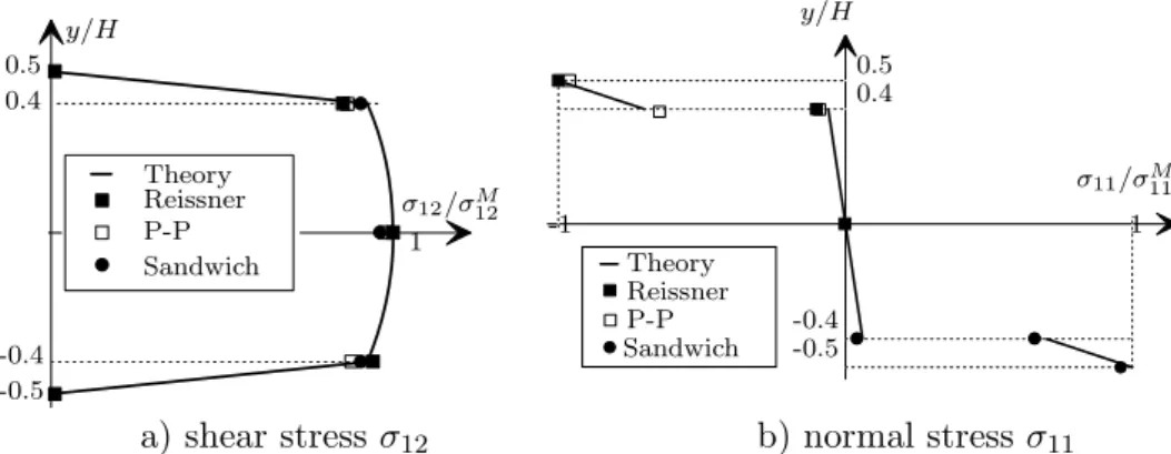
The transverse shear stress distribution through the thickness is shown in figure 4.a. The result for the classical finite element method is not plotted, because this component is not continuous.
Theory Reissner P-P Sandwich σ12/σ12M y/H 0.5 0.4 -0.4 -0.5 1 Theory Reissner P-P Sandwich σ11/σM11 y/H 0.5 0.4 -0.4 -0.5 1 -1
a) shear stress σ12 b) normal stress σ11
Figure 4. Comparison of stress distribution through the thickness at x = L/4
Figure 4.b shows the distribution of σ11 through the thickness. Results
obtained by Reissner’s method and post-processing are only plotted for σ11/σM11 < 0. For hybrid sandwich elements, they are plotted for σ11/σ11M
the interfaces. This figure shows that Reissner’s method leads to a exceeding continuity. Our elements and post-processing methods give an appropriate shape of this discontinuous component.
From figures 3 and 4 it is clear that the presented methods yield results in agreement with the theory, for displacements as well as for the stress distribution through the thickness, and especially at interfaces.
4.2. A SANDWICH PLATE
We now extend the previous example to 3D. Let us consider a simply sup-ported square plate under uniform pressure, as shown in figure 5. The core represents 80% of the total height H, and L/H = 12, with L the length of the side of the plate. The reference solution is given in (Pagano, 1970).
simply supported uniform pressure
Figure 5. Symply supported square sandwich plate
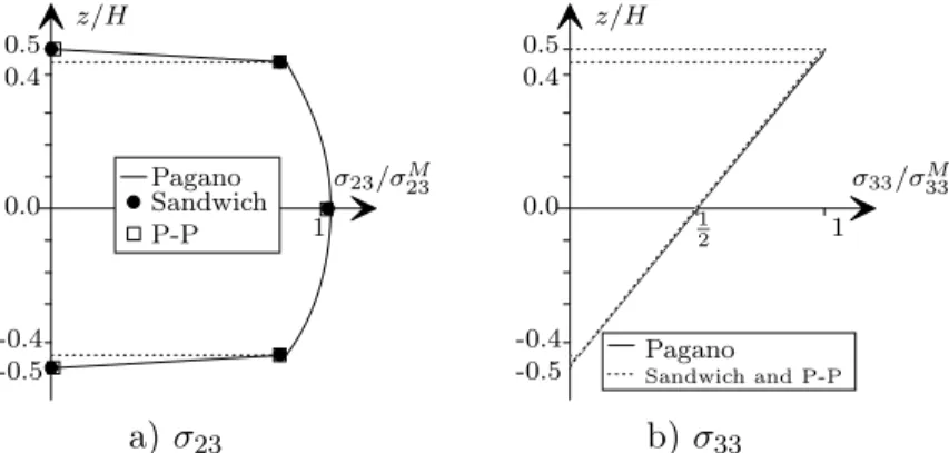
Keeping the previous example in mind, we limit our study to the dis-tribution of σ23 and σ33 through the thickness of the plate. These results
are shown in figure 6.
Pagano Sandwich P-P z/H σ23/σM23 0.5 0.4 0.0 -0.4 -0.5 1 Pagano Sandwich and P-P z/H σ33/σ33M 0.5 0.4 0.0 -0.4 -0.5 1 1 2 a) σ23 b) σ33
8 V. MANET ET AL.
5. Conclusion
The two different approaches, the hybrid sandwich finite elements and the post-processing, have been presented and assessed. From that, we can draw the following conclusion:
− both methods give good results for displacements as well as for stresses: i) only required stress components are continuous at the interfaces and the force equilibrium state is fulfilled; ii) at the free edge of structures, the normal stress vector, σijnj, converges to zero.
The hybrid sandwich finite elements are formulated without assump-tion of the theory of laminated plates. Even though they have a little higher number of degrees of freedom, they represent mechanical be-haviours of the sandwich plates in a more realistic way.
− the post-processing methods permit to use directly the displacement results obtained by any existing FEM softwares.
The computing time of the present post-processing methods is a little higher than the direct computation, which uses only shapes functions ({σ} = [D] [L] [Nu] {q}) but has been shown to be numerically the
worst, as explained in (Hinton, 1974). Most of FEM programs use more sophisticated methods, generally a local least square method (ANSYS for example) to compute nodal stresses. The present post-processing methods have the same computation time as these methods, but ob-tains the same accuracy with fewer elements.
We can emphasize that the two present approaches permit to calculate displacements and stresses in an accurate way, and that they can be easily implemented in existing FEM softwares.
References
Hinton, E. and Campbell, J. S. (1974) Local and global smoothing of discontinuous finite element functions using a least squares method, Int. J. for Num. Meth. in Eng. 8, pp. 461–480.
Lerooy, J.-F. (1983) Calcul des contraintes de cisaillement transversales dans les struc-tures mod´erement ´epaisses, PhD thesis, Institut National Polytechnique de Lorraine. Manet, V. and Han, W.-S. (1997) La mod´elisation des plaques sandwich par ´el´ements finis hybrides et ses applications, Actes du troisi`eme colloque national en calcul des structures 2, Presses acad´emiques de l’Ouest, Nantes, pp. 657–663.
Pagano, N.J. (1970) Exact solutions for rectangular bidirectional composites and sand-wich plates, J. Composite Materials 4, pp. 20–34.
Teti, R. and Caprino, G. (1989) Mechanical behavior of structural sandwiches, Sandwich Construction, pp. 53–67.
Washizu, K. (1982) Variational methods in elasticity and plasticity, Pergamon Press. Zienkiewicz, O.C. and Taylor, R.L. (1994) The Finite Element Method 1, MacGraw-Hill,