HAL Id: hal-01863885
https://hal.archives-ouvertes.fr/hal-01863885
Submitted on 29 Aug 2018
HAL is a multi-disciplinary open access
archive for the deposit and dissemination of
sci-entific research documents, whether they are
pub-lished or not. The documents may come from
L’archive ouverte pluridisciplinaire HAL, est
destinée au dépôt et à la diffusion de documents
scientifiques de niveau recherche, publiés ou non,
émanant des établissements d’enseignement et de
Distributing Relational Model Transformation on
MapReduce
Amine Benelallam, Abel Gómez, Massimo Tisi, Jordi Cabot
To cite this version:
Amine Benelallam, Abel Gómez, Massimo Tisi, Jordi Cabot.
Distributing Relational Model
Transformation on MapReduce.
Journal of Systems and Software, Elsevier, 2018, 142, pp.1-20.
�10.1016/j.jss.2018.04.014�. �hal-01863885�
Distributing Relational Model Transformation on
MapReduce
Amine Benelallama,∗, Abel Gómezc, Massimo Tisib, Jordi Cabotd,c
aDiverSE team (Univ Rennes, Inria, CNRS, IRISA) 263 Avenue Général Leclerc, 35000
Rennes, France
bIMT Atlantique, LS2N (UMR CNRS 6004). 4, Rue Alfred Kastler, 44300, Nantes, France cUniversitat Oberta de Catalunya. Av. Carl Friedrich Gauss, 508860 Castelldefells, Spain
dICREA. Passeig de Lluís Companys, 23, 08010 Barcelona, Spain
Abstract
MDE has been successfully adopted in the production of software for several domains. As the models that need to be handled in MDE grow in scale, it becomes necessary to design scalable algorithms for model transformation (MT) as well as suitable frameworks for storing and retrieving models efficiently. One way to cope with scalability is to exploit the wide availability of distributed clusters in the Cloud for the parallel execution of MT. However, because of the dense interconnectivity of models and the complexity of transformation logic, the efficient use of these solutions in distributed model processing and persistence is not trivial.
This paper exploits the high level of abstraction of an existing relational MT language, ATL, and the semantics of a distributed programming model, MapReduce, to build an ATL engine with implicitly distributed execution. The syntax of the language is not modified and no primitive for distribution is added. Efficient distribution of model elements is achieved thanks to a distributed persistence layer, specifically designed for relational MT. We demonstrate the effectiveness of our approach by making an implementation of our solution publicly available and using it to experimentally measure the speed-up of the transformation system while scaling to larger models and clusters.
Keywords: Model Transformation; Distributed Computing; MapReduce; ATL; NeoEMF
∗Corresponding author. Note this work has been carried out during the PhD thesis of
Amine Benelallam within the AtlanModels team.
Email addresses: [email protected] (Amine Benelallam), [email protected] (Abel Gómez), [email protected] (Massimo Tisi), [email protected] (Jordi
1. Introduction
Model-Driven Engineering (MDE) has been successfully embraced in several domains for automating software development and manufacturing maintainable solutions while decreasing cost and effort. Indeed, recent work has shown the benefits of MDE in applications for the construction industry [1] (for
commu-5
nication of building information and inter-operation with different tools and actors), modernization of legacy systems [2], learning and Big Data analytics [3]. The AUTomotive Open System ARchitecture (AUTOSAR) used in the develop-ment of automotive software systems, and the Building Information Modeling (BIM [1]) are two successful standards involving MDE development principles
10
in the software lifecycle for more than ten years and twenty years respectively. Model query and transformations are key operations to guarantee these benefits. A model transformation (MT) is an operation responsible for translating one model to another. A complex transformation written in one of the general purpose languages (GPLs) can be extremely large and unmaintainable. Fortunately,
15
model query and transformation languages come to the rescue, having been designed to help users in specifying and executing model-graph manipulation operations efficiently. They provide adequate constructs and facilities to specify modular and reusable transformations with less effort. The relational paradigm is the most popular among MT languages, based on the declarative definition of
20
rules relating input and output model elements. Relational model transformations use tracing mechanisms to instate these relations.
Despite all these promises, the MDE approach is not widely applied to large-scale industrial systems. This is mainly due to the serious scalability issues that the current generation of MDE tools is facing [4, 5, 6]. Indeed, according to
25
existing empirical assessments from industrial companies adopting MDE [4, 7], the lack of tools and technologies supporting collaboration and scalability are the substantial disadvantages in MDE. Such large systems exhibit a growing complexity in design, as well as the need to handle an increasing amount of data. For example, BIM contains a rich set of concepts (more than eight hundred) for
30
modeling different aspects of physical facilities and infrastructures. A building model in BIM is typically made of several gigabytes of densely interconnected graph nodes. The model has been growing in time by incrementally integrating different aspects and stakeholders [8]. The AUTOSAR size has been similarly growing [9, 10]. Therefore, there is a calling need to develop a new generation of
35
tools capable of coping with large models. 1.1. Problem statement
Foremost, MT operations involve mainly graph matching and traversing techniques. Such operations are CPU-consuming, which raises serious scalability issues as graphs grow in scale and complexity. Consequently, graph processing
40
problems in general, and MTs in particular, can exceed the resources of a single machine (CPU). For example, in our experiments, we show how typical MT tasks in the reverse-engineering of large Java code bases may take several hours to compute in local.
One way to overcome these issues is exploiting distributed systems for
paral-45
lelizing model manipulation (processing) operations over computer clusters. This is made convenient by the recent wide availability of distributed clusters in the Cloud. MDE developers may already build distributed model transformations by using a general-purpose language and one of the well-known distributed programming models such as MapReduce [11] or Pregel [12]. However such
50
development is not trivial, especially since distributed programming requires familiarity with concurrency and distribution theory that is not common among MDE application developers, in particular when the set of possible execution paths can be large, and transformation result can be non-deterministic. Dis-tributed programming also introduces a completely new class of errors w.r.t.
55
sequential programming, which is linked to task synchronization and shared data access. Finally, it entails complex analysis for performance optimization, for instance, balancing computation load, and maximizing data locality. To summarize, we argue that the growth in data and complexity that is being experienced by the industry is ahead of the current generation of MT tools.
60
This hampers the adoption of MDE in industrial contexts. Therefore, a new generation of MT engines should be provided.
1.2. A distributed platform for relational MTs
In previous work, Clasen et al. [13] draw the first lines towards a conceptual framework for handling the transformation of very large models (VLMs) in
65
the Cloud. Their vision includes essentially two bricks, a model transformation engine and a model access and persistence framework, discussing different possible alternatives. In this paper, we provide a practical solution for these bricks, opting for the data-distribution scheme.
We introduce a distributed platform for running relational MT in the Cloud.
70
We show that relational MTs, thanks to their specific level of abstraction, can be provided with semantics for implicit distributed execution. While we use the rule-based language ATL (AtlanMod Transformation Language [14]) to exemplify our approach, our distribution approach is applicable to the class of relational model transformation languages. We show that thanks to the properties of the ATL
75
language, interactions among rule applications are reduced. The distribution in our proposed framework is implicit, i.e. the syntax of the MT language is not modified and no primitive for distribution is added. Hence developers are not required to have any acquaintance with distributed programming. The semantics we propose is aligned with the MapReduce computation model, thus, showing
80
that rule-based MT fits in the class of problems that can be efficiently handled by the MapReduce abstraction.
Distributed computation models like MapReduce are often associated with persistence layers for accessing distributed data. In our second contribution, we propose a new model-persistence backend, NeoEMF/Column, that provides
85
support for transparently decentralized persistence and access on top of a dis-tributed column store. NeoEMF/Column provides lightweight serialization/de-serialization mechanisms of data communicated across the network and concur-rent read/write from/to the underlying backend.
We demonstrate the effectiveness of the approach by making an
implementa-90
tion of our solution publicly available1and by using it to experimentally measure the speed-up of the transformation system while scaling to larger models and clusters, and more complex transformations. To do so, we use two well-known model transformations, ControlFlow2Dataflow and Class2Relational. The paper illustrates in detail the integration of two components introduced in our previous
95
work [15, 16]. In particular, we extend this work by providing the big picture of the ATL-MR approach, contributing precise definitions and properties(Section 4), carefully analyzing ACID properties required by distributed MTs and implement-ing them on top of NeoEMF/Column (Section 6), and deepenimplement-ing on failure management and data distribution(Section 7). Finally, we evaluate the scalability
100
and performance of ATL-MR on top of NeoEMF/Column (Section 8). 1.3. Outline of the paper
The rest of the paper is structured as follows. Section 2 discusses the main related work in scalable MT and persistence. This section highlights the main limitations of existing approaches and tools in terms of scalability, then
105
positions our framework w.r.t. them. Section 3 describes the running case of the paper and uses it to introduce the syntax of ATL and its execution semantics. Later, it briefly outlines the main concepts of the MapReduce programming model. Afterwards, Section 4 gives an overview of our framework for distributed MTs. It starts by presenting some definitions and properties
110
to simplify the understanding of our approach, then describes the different steps of the distributed transformation process. Section 5 extends our previous work on a distributed engine for MTs with ATL on MapReduce [15]. Section 6 introduces our distributed persistence framework and its support for the set of ACID properties guaranteeing consistent model transformations. Section 7
115
illustrates the integration of processing and persistence layer. Section 8 discusses the evaluation results of our solution when applied to two use cases with different complexity. Finally, Section 9 concludes our paper and outlines some future work.
2. Related Work
120
Model transformation operations may involve intensive read/write from/to models. These models are traditionally stored in a persistence backend. Hence, the performance of a MT engine could be highly impacted by the performance of the underlying persistence backend. For example, the latency due to read and write operations may severely affect the execution time of a MT. In this
125
section, alongside approaches on scalable MTs, we present related work on scalable persistence. First, we introduce related work attempting to improve graph and model processing performance, namely, parallel and distributed model/graph transformation approaches. Then, we review related work on
scalable persistence organized by types of persistence backends, File-based,
SQL-130
based, and NoSQL-based. Finally, we discuss the limitations and drawbacks of existing MT approaches and examine the appropriateness of current solutions for model persistence to distributed MTs.
2.1. Distributed and parallel graph processing
Parallel and distributed graph transformation is a well-studied problem, and
135
well-defined fundamentals have been proposed in several works. In parallel and distributed graph transformations, rule applications are structured in both temporal and spatial dimensions. Graphs are split into sub-graphs for local transformations, then joined again to form a global graph [17]. Two main families of approaches have been proposed, shared memory (parallel) and message
140
passing (distributed). In what follows, we examine existing solutions in parallel and distribute MTs. Afterwards, we briefly discuss some alternative execution semantics for scalable transformations, then we present some high-level languages for distributed data-parallel computing.
2.1.1. Distribution for graph processing languages
145
Among distributed graph transformation proposals, a recent one is Mezei et al. [18]. It is composed of a transformation-level parallelization and a rule-level parallelization with four different matching algorithms to address different distribution types. In another work [19], Izso et al. present a tool called IncQuery-D for incremental query in the Cloud. This approach is based on a distributed
150
model management middleware and a stateful pattern matcher framework using the RETE algorithm. The approach has shown its efficiency, but it addresses only distributed model queries while we focus on declarative transformation rules.
Two approaches map a high-level graph transformation language to the Pregel
155
programming model [20, 21]. Krause et al. [20] proposed a mapping of a graph transformation language and tool, Henshin, to the "BSP model transformation framework" on top of the BSP model. The approach is based on a code generator that translates the graph transformation rules and transformation units into a Pregel program. The matching phase is split into a series of local steps. A local
160
step inspects if a local constraint is satisfied and generates, extends, or merges a set of partial matches. A search plan generation algorithm is responsible for the generation of local steps.
In a similar approach, Tung et al. [21] implemented their own DSL for the specification of graph transformations. This DSL is also compiled into a Pregel
165
program and executed over a distributed cluster. The DSL inherits most of its constructs from UnCAL, a query language and algebra for semi-structured data based on structural recursion. The semantics of UnCAL was improved to support the basic Pregel skeletons. In contrast to the previous approach, this one supports successive applications of queries/transformations. In particular,
170
both approaches implemented their framework on top of Giraph, an open-source implementation of the Pregel model.
Besides our work, the only other proposal addressing relational MT dis-tribution is Lintra, by Burgueño et al. [22], based on the Linda coordination language. Lintra uses the master-slave design pattern, where slaves are in charge
175
of executing in parallel the transformation of sub-models of the input model. The same authors propose a minimal set of primitives to specify distributed model transformations, LintraP [23]. With respect to our approach, Lintra requires to explicitly use distribution primitives, but it can be used in principle to distribute any transformation language by compilation.
180
2.1.2. Shared-memory parallelization for graph processing languages
Shared-memory parallelization is a closely related problem to distribution. For model transformation, Tisi et al. [24] present a systematic two-steps approach to parallelize ATL transformations. The authors provide a multi-threaded implementation of the ATL engine, where each rule is executed in a separate
185
thread for both steps. The parallel ATL compiler and virtual machine have been adapted to enable a parallel execution and reduce synchronization overhead.
A similar approach for parallel graph transformations in multi-core sys-tems [25] introduces a two-phase algorithm (matching and modifier) similar to ours. Bergmann et al. propose an approach to parallelizing graph
transforma-190
tions based on incremental pattern matching [26]. This approach uses a message passing mechanism to notify of model changes. The incremental pattern matcher is split into different containers, each one is responsible for a set of patterns. The lack of distributed memory concerns makes these solutions difficult to adapt to the distributed computing scenario. Moreover, in these cases, the authors
195
investigate task distribution, while we focus on data distribution, especially for handling VLMs.
2.1.3. Alternative execution semantics for scalable transformations
The idea of overloading the execution semantics of model transformation languages in order to improve scalability is not new. In particular, several works
200
introduced incremental or streaming computation semantics.
Incremental computing is a software feature aiming at saving the program re-computation time every time a piece of data changes. It identifies the outputs which depend on the changed data, then updates their value. EMF-IncQuery [27, 28] is a declarative model query framework for EMF models using the graph
205
pattern formalism as a query specification language. It aims at bringing the benefits of graph pattern-based queries and incremental pattern matching to the EMF ecosystem. Bergmann et al. [29] proposed an approach to integrate incremental pattern matching into existing legacy systems built over RDBs. It translates graph patterns/rules into SQL triggers. Additional tables are added
210
to store cached relationships. Jouault et al. [30] introduced an approach for incremental transformations in ATL. Neither ATL’s syntax nor its semantics sustained any change, except for some minimal changes to the compiler. Giese et al. [31] proposed an approach to automatically induce automatic incremental synchronization using Triple Graph Grammar (TGG).
Streaming computation is a computer programming paradigm equivalent to event stream processing and reactive programming. Several approaches that support reactive and streaming model transformation have been proposed [32, 33, 34]. VIATRA 3 [32] is a source incremental event-driven model transformation platform based on the reactive programming paradigm. VIATRA 3 offers a
220
family of internal DSLs to specify advanced tool features built on top of existing languages like EMF-IncQuery and Xtend. VIATRA-CEP [33] is an engine for streaming model transformations by combining incremental transformation and complex event processing. It includes a DSL for defining atomic event classes and combining them into complex patterns and events. Martínez et al. [34]
225
introduced a reactive model transformation engine for ATL. This work combines efforts on enabling incrementality and lazy evaluation of ATL transformations. These approaches are well-suited to the model-driven applications involving frequent runtime updates. The transformation engine takes care of re-executing only the necessary computation affected by the update. For efficient execution
230
of one-shot transformation on VLMs, these approaches fail drastically. 2.1.4. High-level languages for distributed data-parallel computing
Many high-level languages for data-parallel computing targeting distributed programming models have been proposed. However, these languages are not designed for performing distributed model transformations.
235
Microsoft SCOPE [35], Pig Latin [36], and HiveQL [37] are high-level SQL-like scripting languages targeting massive data analysis on top of MapReduce. Pig Latin and SCOPE are hybrid languages combining both forces of a SQL-like declarative style and a procedural programming style using MapReduce primitives. They provide an extensive support for user-defined functions. Hive
240
is a data warehousing solution built on top of Hadoop. It comes with a SQL-like language, HiveQL, which supports data definition statements to create tables with specific serialization formats, and partitioning and bucketing columns.
DryadLINQ is a language designed to target the Dryad [38] engine, a general-purpose distributed execution engine for coarse-grain data-parallel applications.
245
Unlike PigLatin or SCOPE, which introduce new domain-specific languages, DryadLINQ is embedded as constructs within existing programming languages. A program written in DryadLINQ is a sequential program composed of expressions specified in LINQ, the .NET Language Integrated Query. The expressions perform arbitrary side-effect-free operations on datasets and can be debugged
250
using standard .NET development tools. 2.2. Scalable persistence of VLMs
The interest on scalable model persistence has grown significantly in recent years. Nonetheless, existing approaches are still not suitable to manage this kind of artifacts both in terms of processing and performance.
255
2.2.1. XMI-based approaches
Models stored in XMI need to be fully loaded in memory for persistence. The lack of support for lazy or partial loading of models hampers handling VLMs
not fitting in a memory of a single machine. Moreover, this persistence format is not adapted to developing distributed MDE-based tools. One way to tackle
260
scalability issues while sticking to the XMI representation is by decomposing the model into fragments. Amálio et al. [39] proposed a mathematical ground for this, based on the ideas of modularity and separation of concerns. Below, we investigate the state-of-the-art tools and frameworks for persisting EMF-based models and draw down their limitations.
265
EMF fragments [40] is a hybrid persistence layer for EMF models aimed at achieving fast storage and navigation of persisted data. EMF-Fragments uses annotations to decompose a model into smaller documents. A similar approach is EMF Splitter [41], it borrows the modularity structure used in Eclipse for Java projects organization to decompose the models. Both approaches rely on
270
the proxy resolution mechanism used by EMF for inter-document relationships. EMF Fragment supports MongoDB, Apache HBase, and regular files, while EMF Splitter supports only XMI files.
2.2.2. Relational-based approaches
Connected Data Objects (CDO) model repository [42] is the de facto
stan-275
dard solution to handle large models in EMF by storing them in a relational database. It was initially envisioned as a framework to manage large models in a collaborative environment with a low memory footprint. However, different expe-riences have shown that CDO does not scale well to very large models [43, 44, 45]. CDO implements a client-server architecture with transactional and notification
280
facilities where model elements are loaded on demand. CDO servers (usually called repositories) are built on top of different data storage solutions. However, in practice, only relational databases are commonly used.
2.2.3. NoSQL-based approaches
Barmpis and Kolovos [46] suggest that NoSQL databases would provide better
285
scalability and performance than relational databases due to the interconnected nature of models. Morsa [44] was one of the first approaches to provide persis-tence of large-scale EMF models using NoSQL databases. Specifically, Morsa uses MongoDB [47], a document-oriented database, as its persistence backend. Morsa can be used seamlessly to persist large models using the standard EMF
290
mechanisms. As CDO, Morsa is built using a client-server architecture. Morsa provides on-demand loading capabilities together with incremental updates to maintain a low workload. The performance of the storage backend and their own query language (MorsaQL) have been reported in [44] and [45].
Mongo EMF [48] is another alternative to storing EMF models in MongoDB.
295
Mongo EMF provides the same standard API as previous approaches. However, according to the documentation, the storage mechanism behaves slightly different than the standard persistence backend (for example, when persisting collections of objects or saving bi-directional cross-document containment references). Using Mongo EMF to replace another backend in an existing system, requires an
300
Table 1: Summary of distributed and parallel MTs approaches
Approach Paradigm Exec. Mode Concurrency EMF Integ. Graph Rel. Shared Dist. Mem. Disk
VMTS-para # # # # VMTS-dist # # # # ATL-para # # # LinTra # # # Henshin # # # # Tung et al. # # # #
Legend: feature supported, # feature not supported
Table 2: Summary of model persistence approaches
Approach Store Lazy loading Access Conc. write
CDO SQL fine centralized yes
Mongo EMF NoSQL fine centralized yes
Morsa NoSQL fine local no
EMFSplit XMI coarse local diff. splits*
EMFfragments XMI coarse decentralized diff. splits
(*)Concurrent writes are not allowed at the file level. Permitted only on different files.
2.3. Current limitations to scalable MT and persistence
In this section, we reviewed existing approaches aiming at optimizing graph processing, with a particular focus on graph transformation operations. Moreover, we presented state-of-the-art tools for the persistence of VLMs in EMF. Tables 1
305
and 2 summarize the limitations of MT approaches and model persistence tools respectively.
While most approaches in graph/model transformation focus on the paral-lelization of the transformation using the graph paradigm, only two approaches focus on relational model transformation, parallel-ATL [24] and LinTra [22].
310
Nonetheless, parallel-ATL is still limited to the resources of one machine, while LinTra is not compatible with existing EMF-based applications, especially pre-cluding some runtime interactions with EMF components. It translates the transformation rules together with in-/output metamodels to a Linda-specific format. As for the remaining approaches, visibly, none of them has a clear
315
support of concurrent write on target models, nor a clear support for complex transformation rules (e.g. rules involving multiple input patterns). Our solution is designed to address these missing features.
Concerning the solutions for persisting EMF models, we observed that, while most of the existing approaches scale in some scenarios, they expose a
320
few limitations that are crucial to distributed model Transformations. EMF Fragments and EMF Splitter require a good fragmentation from the user. They support lazy loading only at the chunk level. As a consequence, complex queries may lead to loading the whole model even though some elements are not accessed. Moreover, EMF Fragments on top of HBase is not transparent with regard to
FlowInstr txt : String Var name : String Method Param SimpleStmt cfNext * use * def * localStmts *
(a) ControlFlow metamodel excerpt
FlowInstr txt : String Method SimpleStmt dfNext * localStmts *
(b) DataFlow metamodel excerpt Figure 1: Simplified ControlFlow and DataFlow metamodels
model distribution. Queries and transformations need to explicitly take into account that they are running on a part of the model and not the whole model. These backends assume to split the model into balanced chunks. This may not be suitable for distributed processing, where the optimization of computation distribution may require uneven data distribution. Finally, existing solutions
330
using a client-server architecture (e.g. CDO over a distributed database) use a single access point. Even when model elements are stored in different nodes, access to model elements is centralized, since elements are requested from and provided by a central server. This constitutes a bottleneck and does not exploit a possible alignment between data distribution and computation distribution.
335
With a growing size of clients, the single access point can rapidly turn into a limitation.
We extended an existing multi-layer persistence backend for VLMs in EMF with support for concurrent read-write. The distribution is completely trans-parent for EMF-based tools, and the alignment between data distribution and
340
computation distribution is alleviated. Moreover, our solution relies on the CAP (Consistency, Availability and Partitioning tolerance) principle, where we sacrifice some ACID properties in order to achieve better global performance while guaranteeing full consistency.
3. Background
345
Before going into the details of our proposal, in this section, we present the necessary background. First, we introduce the ATL transformation language by means of a case study. We discuss a set of properties that reduces inter-rules communication. Later, we introduce the MapReduce programming model and describe its properties and features.
350
3.1. The ATL transformation language
While our distribution approach is applicable to the class of relational model transformation languages, in this paper, we refer to the ATL language to exem-plify this class. To elucidate the discussion of our approach, we refer throughout the paper to a single case study related to the analysis of dataflows in Java
355
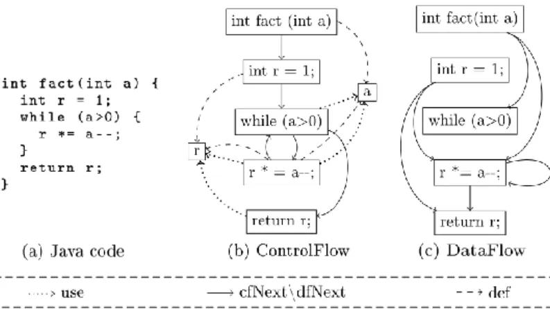
Figure 2: ControlFlow2DataFlow transformation example
by the Transformation Tool Contest (TTC) 2013 [49] as a benchmark for MT engines.
Excerpts of the source and target metamodels of this step are shown in Fig. 1. In a control-flow diagram (Fig. 1a), a FlowInstruction (FlowInstr) has a field
360
txt containing the textual code of the instruction, a set of variables it defines or writes (def ), and a set of variables it reads (use). A method may contain a set of simple statements localStmts. A FlowInstruction points to the potential set of instructions that may be executed after it (cfNext ). Method signatures and SimpleStatements (SimpleStmt) are kinds of FlowInstruction. A Parameter is a
365
kind of Variable that is defined in method signatures.
The dataflow diagram (Fig. 1b) has analogous concepts of FlowInstruction, Method and SimpleStatements but a different topology based on the dataflow links among instructions (dfNext ). For every flow instruction n, a dfNext link has to be created from all nearest control-flow predecessors m that define a
370
variable which is used by n.
Fig. 2 shows an example of models for each metamodel, derived from a small program calculating a number factorial. For readability reasons, and in order not to congest our graphs, containment references are omitted. As it can be seen in the figure, the transformation changes the topology of the model graph,
375
the number of nodes and their content, and therefore can be regarded as a representative example of general transformations. In this paper we refer to an ATL implementation of the transformation named ControlFlow2DataFlow and available at the tool website2.
Languages like ATL are structured in a set of transformation rules
encapsu-380
lated in a transformation unit. These transformation units are called modules (Listing 1, line 1). The query language used in ATL is the OMG’s Object
Constraints Language (OCL) [50]. A significant subset of OCL data types and operations is supported in ATL. Listing 1 shows a subset of the rules in the ControlFlow2DataFlow transformation.
385
Input patterns are fired automatically when an instance of the source pattern (a match) is identified, and produce an instance of the corresponding target pattern in the output model. Implicitly, transient tracing information is built to associate input elements to their correspondences in the target model.
Source patterns are defined as OCL guards over a set of typed elements, i.e.
390
only combinations of input elements satisfying that guard are matched. In ATL, a source pattern lays within the body of the clause ’from’ (Listing 1, line 15). For instance, in the rule SimpleStmt, the source pattern (Listing 1, line 16) matches an element of type SimpleStmt that defines or uses at least a variable. Output patterns, delimited by the clause ’to’ (Listing 1, line 18) describe how
395
to compute the model elements to produce when the rule is fired, starting from the values of the matched elements. E.g., the SimpleStmt rule produces a single element of type SimpleStmt. A set of OCL bindings specify how to fill each of the features (attributes and references) of the produced elements. The binding at line 20 copies the textual representation of the instruction, the binding at
400
line 21 fills the dfNext link with values computed by the computeNextDataFlows OCL helper. The rule for transforming methods is similar (Listing 1, lines 3-12). ATL matched rules are executed in two phases, a match phase and an apply phase. In the first phase, the rules are applied to source models’ elements satisfying their guards. This execution strategy is recognized in the community
405
as Map Entities before Relations/Objects before Links model transformation design pattern [51]. Each single match corresponds to the creation of an explicit traceability link. This link connects three items: the rule that triggered the
Listing 1: ControlFlow2DataFlow - ATL transformation rules (excerpt) 1 module C o n t r o l F l o w 2 D a t a F l o w ; 2 c r e a t e O U T : D a t a F l o w from I N : C o n t r o l F l o w ; 3 r u l e M e t h o d { 4 from 5 s : C o n t r o l F l o w ! M e t h o d 6 to 7 t : D a t a F l o w ! M e t h o d ( 8 t x t <− s . t x t , 9 l o c a l S t m t s <− s . l o c a l S t m t s , 10 d f N e x t <− s . c o m p u t e N e x t D a t a F l o w s ( ) 11 ) 12 } 13 14 r u l e S i m p l e S t m t { 15 from 16 s : C o n t r o l F l o w ! S i m p l e S t m t ( n o t ( s .def−> 17 i s E m p t y ( ) and s . u s e−>i s E m p t y ( ) ) ) 18 to 19 t : D a t a F l o w ! S i m p l e S t m t ( 20 t x t <− s . t x t , 21 d f N e x t <− s . c o m p u t e N e x t D a t a F l o w s ( ) 22 ) 23 }
application, the match, and the newly created output elements (according to the target pattern). At this stage, only output pattern elements type is considered,
410
bindings evaluation is left to the next phase.
The apply phase deals with the initialization of output elements’ features. Every feature is associated to a binding in an output pattern element of a given rule application. Indeed, a rule application corresponds to a trace link. Features initialization is performed in two steps, first, the corresponding binding
415
expression is computed. Resulting in a collection of elements, it is then passed to a resolution algorithm (called resolve algorithm) for final update into the output model. The resolve algorithm behaves differently according to the type of each element. If the type is primitive (in case of attributes) or target, then it is directly assigned to the feature. Otherwise, if it is a source element type, it is
420
first resolved to its respective target element – using the tracing information – before being assigned to the feature. Thanks to this algorithm we are able to initialize the target features without needing to navigate the target models. The resolveTemp, a generalization of the resolve algorithm, is also invoked on a source element but returns a specific target model element identified by a name
425
of the rule and a name of a target pattern belonging to this rule. A normal resolve can be regarded as a resolveTemp call having as parameters a default rule name and the name of the first target pattern element.
As result of ATL’s execution semantics, especially four specific properties of the language (below), inter-rule communication is made discernible and the
430
odds of running into race conditions are minimized. More precisely, interaction among ATL transformation rules are reduced to bindings resolution, where a target element’s feature needs to link to other target elements created by other rules:
Property 1. Locality: Each ATL rule is the only one responsible for the
435
computation of the elements it creates, i.e., the rule that creates the element is also responsible for initializing its features. In the case of bidirectional references, responsibility is shared among the rules that create the source and the target ends of the reference.
Note that if a transformation language does not satisfy this property, a way
440
to lower the data communication cost would be by making sure that different rules sharing update task reside on the same machine.
Property 2. Single assignment on target properties: The assignment of a single-valued property in a target model element happens only once in the transformation execution. Multi-valued properties can be updated only by adding
445
values but never deleting them.
If a language does not guarantee this property, one way of communicating less data is by local aggregating operations. Let’s take for instance the example of a rule that, for every rule application increments a variable, instead of sending a bunch of increment values, it would be recommended to aggregate them and
450
Remote read <+, 1> <+ , 1> <*, 1> < , 1> <+, 1> <*, 1> < , 1> <*, 1> <+, 1> Log0 Log1 Log2 Log3 Log4 Log5 Log6 Log7 Log8 S P LI T 1 S P LI T 2 S P LI T 3 Write result <*, 1> <*, 1> <*, 1> < , 1> < , 1> <+, 1> <+, 1> <+, 1> <+, 1> Map Reduce Worker
Read split Localwrite <*, 3>
< , 2>
<+, 4>
Record
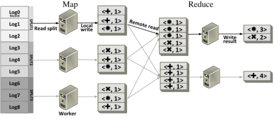
Figure 3: MapReduce programming model overview
Property 3. Non-recursive rule application: Model elements that are produced by ATL rules are not subject to further matches. As a consequence, new model elements cannot be created as intermediate data to support the computation.
This differentiates ATL from typically recursive graph-transformation
lan-455
guages. The property should not be confused with recursion in OCL helpers that are responsible for intermediate computations over the source models only but not the target ones.
Property 4. Forbidden target navigation: Rules are not allowed to nav-igate the part of the target model that has already been produced, to avoid
460
assumptions on the rule execution order.
This property is possible thanks to the resolve algorithm. A way to workaround the non-satisfaction of this property is by making sure that the target elements creation and update happen in two different phases.
3.2. MapReduce
465
MapReduce is a programming model and software framework developed at Google in 2004 [11]. It allows easy and transparent distributed processing of big data sets while concealing the complex distribution details a developer might cross. MapReduce is inspired by the map and reduce primitives that exist in functional languages. Both Map and Reduce invocations are distributed across
470
cluster nodes, thanks to the Master that orchestrates jobs assignment.
Input data is partitioned into a set of chunks called Splits as illustrated in Fig. 3. The partitioning might be monitored by the user through a set of parameters. If not, splits are automatically and evenly partitioned. Every split comprises a set of logical Records, each containing a pair of hkey, valuei.
475
Given the number of Splits and idle nodes, the Master node decides the number of workers (slave machines) for the assignment of Map jobs. Each Map worker reads one or many Splits, iterates over the Records, processes the hkey, valuei pairs and stores locally the intermediate hkey, valuei pairs. In the
meanwhile, the Master receives periodically the location of these pairs. When
480
Map workers finish, the Master forwards these locations to the Reduce workers that sort them so that all occurrences of the same key are grouped together. The mapper then passes the key and list of values to the user-defined reduce function. Following the reduce tasks achievement, an output result is generated per reduce task. Output results do not need to be always combined, especially if
485
they will subsequently be processed by other distributed applications.
Let’s take a closer look at the MapReduce programming model by means of a simple example, depicted in Fig. 3. Assume we have set of log entries coming from a git repository. Each entry contains information about actions performed over a particular file (creation → + , deletion → X, or modification → ∗ ). We
490
want to know how many times each action was performed, using MapReduce. The master evenly splits the entries among workers. For every record (log entry), the map worker extracts the action type and creates a hkey,valuei pair with a key the action itself and value ’1’. In the reduce phase, pairs with the same key are grouped together. In our example, the modification and deletion go to the
495
first reducer, while the creation goes to the second one. For each group, the reducer combines the pairs and creates a hkey,valuei pair, but this time with value the sum of the values with the same key. This value refers to how many times the action occurred in the logs.
A useful optimization feature shipped with MapReduce is the Combiner. It
500
is an optional class taking place right after the map phase, and before the shuffle phase. It operates on pairs originating from the mapper running on the same node. For each set of pairs sharing the same key, values are aggregated in order to combine them into a single pair according to the Combiner class definition. As you can notice, the main benefit using combiners is to reduce the volume of
505
data sent between the Map and Reduce phases, and therefore the time that is taken to shuffle different pairs across the cluster. We use the combiner feature in order to perform a local resolve, which allows us to send fewer traces to the reduce phase.
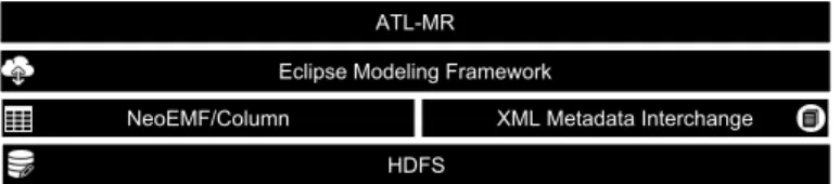
It is to the Distributed File System (DFS) that the MapReduce framework
510
owes its ability to scale to hundreds of machines in a cluster. The master node in MapReduce tends to assign workloads to servers where data to be processed is stored to maximize data locality. An interest of MapReduce is due to its fault-tolerant processing. The Master keeps track of the evolution of every worker execution. If after a certain amount of time a worker does not react, it is
515
considered as idle and the job is re-assigned to another worker. Same for DFS, data is divided into blocks, and copies of these blocks are stored in different nodes across the cluster to achieve a good availability as nodes fail.
Hadoop [52] and Hadoop Distributed File System (HDFS) [53] are the most well-known and widely used open-source implementations of MapReduce and
520
4. Conceptual Framework
In this section, we give a global overview of our distributed MT framework. We first introduce some definitions and properties we believe would help better grasp our data distribution approach. Later, we describe our distributed model
525
transformation process by means of a simple example. 4.1. Definitions
In typical relational MT engines (e.g., the standard ATL and ETL engines), the transformation execution starts by loading the input model. Then the engine applies the transformation by selecting each rule, looking for matches
530
corresponding to the input pattern, and finally generating the appropriate output elements [54]. Each execution of a matched input pattern is called a rule application.
From now on, we denote by E a set of model elements, and M a set of commodity machines in a distributed system S.
535
Definition 1. Let R be a set of model transformation rules. A rule application is defined by the tuple (r, in) where:
• r ∈ R is the rule being applied
• in ⊆ E is the list of source elements matched by the rule r (i.e., the input pattern)
540
In the context of distributed model transformations we define other two properties of rule applications:
• e ∈ in (primary trigger) is a single element elected as the primary trigger of the rule application
• ctx ⊆ E (context) is the subset of model elements accessed to evaluate
545
expressions in r for the rule application. These elements include the elements of the input pattern
Given Definition 1, we consider a MT execution job as the union of elementary rule application execution jobs, where each job is responsible for transforming a single input pattern. In the case of rules with n-ary input pattern (matching a
550
sub-graph), we consider the job of applying the rule to be primarily triggered by one input pattern element. Selecting a primary triggering element for each rule application ensures that, after distributing the source model, a rule application occurs on only one machine, i.e. the one responsible for transforming the triggering element.
555
The distribution of a transformation based on a data-parallel distribution approach over m machines (m = |M|), consists of dividing the input model into m splits and assigning disjoint sub-models of the input model to different machines. Each machine will be then responsible for transforming the assigned subset. In what follows we refer to this set of elements assigned to a machine i
560
by Ai. Given a system S of m machines, the set of assigned elements has the
Property 5. Each element e ∈ Ai is assigned to one and only one set (∀i, j ∈
M, i 6= j =⇒ Ai∩ Aj= ∅ )
In order to transform its set of assigned elements Ai, a machine i needs to
access all the elements that are necessary for the transformation of its assigned elements. We denote this set as:
Di=
[
e∈Ai
dependencies(e)
where dependencies(e) is the union of the contexts of all the rule applications
565
that are primarily triggered by e.
Consequently, every machine i needs to load all the elements Li belonging to
Ai∪ Di.
Typical distributed graph processing presents a higher ratio of data access to computation w.r.t. typical scientific computing applications. In particular,
570
most of the computational complexity of MT rules lies in the pattern matching step, i.e. the exploration of the graph structure. With a naive data distribution scheme, the execution time can be monopolized by the wait time for model elements lookup. Hence, an intelligent assignment of elements to cluster nodes should be performed. For instance, an intelligent data-distribution strategy may
575
try to minimize network traffic by an intelligent assignment (Ai). In particular,
it may try to minimize the number of shared elements, i.e. elements that are needed by multiple nodes (e.g. i and j share Li∩ Lj). The problem is similar to
a well-known problem in the graphs community, Graph-Based Data Clustering with Overlaps [55]. This problem allows clusters overlapping by duplicating (to
580
a given extent) graph vertices or edges. In related work [56], we discuss this problem in more details. We have formalized the problem of model partitioning for distributed model transformations in linear programming and proposed a greedy algorithm for efficient data distribution.
4.2. Overview of the distributed transformation process
585
Figure 4 shows a global overview of our distributed transformation framework by means of a simple example. The transformation is composed of a simple rule that changes the shape of nodes (from Square to Hexagon) but keeps the same ID as well as graph topology. Our distributed cluster is composed of a single master node, data nodes, and task nodes. Data nodes and task nodes communicate with
590
each other through a distributed MOF-compliant model access and persistence API. While task nodes are responsible for transforming the input model or composing the output one, data nodes are responsible for hosting the partial input/output models. Although in our illustration we differentiate between data nodes and task nodes, in real-world clusters, data can be processed in the same
595
node it resides in.
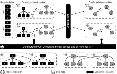
Our distributed model transformation process is divided in three steps, (i) data distribution, (ii) parallel local transformation, and (iii) parallel composition. The coordination phase plays the role of a barrier in which task nodes share their output data among each other for composition.
e h g f a d c b a d c b e h g f
Distributed (MOF-Compliant) model access and persistence API a d c b g e h g f d Coordination
Task node (worker) Data node Concurrent Read/Write
Data distribution Parallel local transformation Parallel global composition
Split 1 Split 2 a b c d e f g h a b c d e f g h a g a g e d e d
Figure 4: A conceptual framework for distributed model transformation
In the first phase, the master node is responsible for assigning source model elements to task nodes (data distribution) for computation. Each task node is responsible for executing the rule application triggered by the assigned elements. These subsets (a.k.a. chunks, splits, or partitions) are designed to avoid any redundant computation in two separate nodes (respecting Property 5). Moreover,
605
since the master node is limited by its memory capacity, we consider a lightweight and memory-friendly assignment mechanism of source model elements. In our example, the master node assigns {a, b, c, d} to the upper node, and the remaining to the second one (as shown in Figure 4).
After assigning source model elements to task nodes, they start processing
610
the transformation in parallel. However, due to the complexity of the pattern matching phase, a task node may have to load additional elements in order for its local transformation to complete (parallel transformation). For instance, in our example, each square needs to traverse the set of its direct neighboring nodes to reproduce the graph topology. In particular, the upper task node needs the
615
elements "g" while the second node needs "d". Because the set of additional elements is known only at runtime, our persistence framework transparently provides task nodes with the ability to access any input element, identified by its UUID, during the transformation execution. This is granted to an on-demand lazy loading mechanism (see Section6). Additionally, all data requests
620
are transparently passed through the persistence layer and task nodes would not be aware of the physical location of the model elements. However, the cost for accessing data is not constant as it is likely influenced by the network I/O.
At the end of the parallel transformation phase, each task node will result in a local output sub-model together with a set of tracing information that
int fact(int a) int r = 1; while (a>0) r *= a--; return r; a r int fact(int a) int r = 1; while (a>0) r *= a--; return r; int fact(int a) int r = 1; while (a>0) r *= a--; return r; Map 1 output Map 2 output Reduce output Input Model
Local match\apply Global resolve
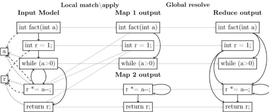
Figure 5: ControlFlow2DataFlow example on MapReduce
has a twofold role. This information does not only contain information about computation already performed but also about the one that needs to be performed in order to compose local output sub-models into a global output model.
The coordination phase plays the role of a synchronization barrier, where, once all task nodes finish their parallel transformation, they exchange trace
630
information about the missing links in order to compose the global model. To avoid network congestion, target sub-models are stored together with the traces, and only a list of UUIDs identifying these traces is passed through the network. In the final phase (parallel composition), missing tracelinks are evenly split to task nodes, and relationships are established between the output sub-models to
635
compose the final output model. The persistence framework enables task nodes to concurrently establish links between any given model elements. Similarly to the previous phase, task nodes can transparently access, at any time, model elements and the transformation traces.
5. Distributed Relational Model Transformation on MapReduce
640
Distributed model-to-model transformation inherits most of the well-known challenges of efficient parallel graph processing, such as poor data locality and unbalanced computational workloads. In particular, implicit data distribution is not trivial for transformation languages where rules applied to different parts of the model can interact in complex ways with each other. The higher is the
645
number of these interactions, the bigger is the volume of data communicated across the network, both at inter and intra-phase levels. In MapReduce, this turns into, more data to serialize, de-serialize, and less network throughput due to congestion. Thanks to ATL properties introduced in Section 3, the possible kinds of interaction among ATL rules is strongly reduced, which allows
650
to decouple rule applications and execute them in independent execution units. In this section, we show how our distributed transformation process has been mapped to the MapReduce programming model, then, we illustrate the alignment of ATL execution semantics to the MapReduce.
5.1. ATL and MapReduce alignment
655
Mostly, distributed (iterative) graph processing algorithms are data-driven, where computations occur at every node of the graph as a function of local graph structure and its intermediate states. The transformation algorithm in ATL could be regarded as an iterative graph processing algorithm with two phases (match and apply described in Section 3) and one intermediate state
660
(matched). Each node of the cluster that is computing in parallel takes charge of transforming a part of the input model.
In our approach, we propose a mapping that aims at reducing cross-machine communication cost. That is by adopting some good practices for scalable graph processing in MapReduce. This is made possible, thanks to the alignment of the
665
ATL distributed execution semantics with MapReduce described below. The proposed mapping is conceptually similar to the original ATL algorithm.
As an example, Figure 5 shows how the ATL transformation of our running example could be executed on top of a MapReduce architecture comprising three nodes, two maps and one reduce workers. The input model is equally
670
split according to the number of map workers (in this case each map node takes as input half of the input model elements). In the map phase, each worker runs independently the full transformation code but applies it only to the transformation of the assigned subset of the input model. We call this phase Local match-apply. Afterwards, each map worker communicates the set of model
675
elements it created to the reduce phase, together with trace information. These trace links (grey arrows in Figure 5) encode the additional information that will be needed to resolve the binding, i.e. identify the exact target element that has to be referenced based on the tracing information. The reduce worker is responsible for gathering partial models and trace links from the map workers,
680
and updating properties value of unresolved bindings. We call this phase Global resolve.
In the following, we briefly describe the distributed execution algorithm, which is decomposed in two phases, the Local match-apply phase assigned to mappers and the Global resolve phase assigned to reducers.
685
Local match-apply
At the beginning of the phase, input splits are assigned to map workers. Each one of these splits contains a subset of the input model for processing. Despite this, each worker can access the whole input models in case it needs additional data for bindings computation. Thanks to our model data mapping, which
690
adheres to good practices in graph data representation [57], model elements together with their adjacent nodes are stored as tuples. Adjacent model elements are accessed lazily and on-demand when it is required by the transformation execution logics. Algorithm 1 illustrates the pseudo-code of the Local match-apply.
695
For every model element in the split, the map function verifies if a rule guard matches and in this case instantiates the corresponding target elements, same as in the regular execution semantics. In the case of rules that match multiple
Algorithm 1: Map function
input : Long key, ModelElement element
1 foreach rule ∈ getApplicableRules(element) do 2 if isMatched(element, rule) then
3 link ← createLink(element, rule); 4 addLink(linkSet, link);
5 foreach binding ∈ getBindings(link) do
6 if isAttribute(binding) then
7 applyAttribute (binding);
8 else
9 foreach ComputedElement ∈ computeBindingExp(binding)
do 10 if isLocal(ComputedElement) then 11 resolvedElement ← resolveTarget(ComputedElement); 12 applyReference(resolvedElement, binding); 13 else 14 addElementToTrace(ComputedElement, binding); 15 storeLink(generatedKey, link);
// generatedKey to decide to which reducer this link will be assigned
elements, the map function would consider the elements of the split as the first element of the matched pattern, and look for combinations of other elements
700
satisfying the guard. For each instantiated output element, a trace link is created connecting source and target elements of the applied rule. Subsequently, the algorithm starts processing the list of property bindings for the instantiated target elements. We extended the behavior of the resolve algorithm to enable handling elements transformed in other nodes, we call this algorithm local
705
resolve. In the case of attribute bindings (lines 6–7), the same standard behavior is preserved, the OCL expression is computed and the corresponding feature is updated accordingly. While bindings related to references connect elements transformed by different rule applications, potentially on different nodes, the resolution is performed in two steps: (i) the OCL expression of
710
the binding computes to a set of elements in the source model and ATL connects the bound feature to these source elements using trace links; (ii) the source-models elements are resolved, i.e. substituted with the corresponding target element according to the rule application trace links. If the source and target elements of the reference are both being transformed in the same node,
715
both steps happen locally (lines 10–12), otherwise trace links are stored and communicated to the reducer, postponing the resolution step to the Global resolve phase. The resolveTemp algorithm behaves similarly. In the Global
resolve phase, unresolved elements coming from the resolveTemp are treated equally to unresolved model elements coming from the normal resolve.
720
Global resolve
At the beginning of the reduce phase, all the target elements are created, the local bindings are populated, and the unresolved bindings are referring to the source elements to be resolved. This information is kept consistent in the tracing information formerly computed and communicated by the mappers. Then it
725
resolves the remaining reference bindings by iterating over the trace links. For each trace link, the reducer iterates over the unresolved elements of its property traces, resolves their corresponding element in the output model, and updates the target element with the final references. The pseudo-code for the Global resolve is given in Algorithm 2.
Algorithm 2: Reduce function
input : String key, Set<TraceLink> links 1 foreach link ∈ links do
2 foreach property ∈ getTraceProperties(link) do// unresolved properties
3
4 foreach elmt ∈ getSourceElements(property) do
5 resolvedElement ← resolveTarget(elmt);
6 updateUnresolvedElement(property, trgElmt);
// equivalent to applyReference (element, binding) in map function
730
5.2. ACID properties for atomic model manipulation operations in ATL Distributed computation models like MapReduce are often associated with persistence layers for accessing distributed data. In solutions for Big Data, where scalability is the main requirement, persistence layers sacrifice ACID properties in order to achieve better global performance. In networked shared-data systems,
735
this is also known as CAP theorem [58]. Such properties need to be implemented by the application layer on a need basis.
Hereafter, we reason about the execution semantics of ATL, especially, atomic model manipulation operations (as coming from the MOF specification). Our objective is to extract the minimal set of ACID properties to be guaranteed
740
for a consistent output model. This reasoning is conducted while taking into consideration the model access modes and the possible interactions between model manipulation operations.
As no definition of a transaction has been carried in the formal MOF specifi-cation, in our study, we consider that each model manipulation operation on a
745
single element runs in a separate transaction. This definition is similar to the one adopted by the CAP theory. In our analysis, we rely on the semantics of the
MOF reflection API, especially the methods used by the ATL engine. Hereafter, we give a brief description of the MOF’s Reflection API.
Table 3: Access modes in ATL transformations
Match Apply
Input read-only
Output write-only
Trace write-only read-only
In model-to-model transformations with ATL, models are never accessed in
750
read-write mode but only in read-only mode or write-only mode. Precisely, while source models are always read-only and target models are always write-only, trace models are, depending on the phase, either read-only (apply phase) or write-only (match phase). Table 3 summarizes different access modes per model-kind\phase.
755
Moreover, in our distributed transformation framework, we identify two different scopes of computation, depending on the phase. The computation can run either in a local scope (Local match/apply), or a global scope (Global resolve). In the local scope, all the write operations happen in local. Data is always created and manipulated by the same task node. As a result, model
760
manipulation operations on the same model element never run concurrently. On the other hand, concurrency may take place in the global scope, and different machines can modify the same element at the same time.
Regardless of the computation scope, models that are accessed in read-only mode are subject only to side-effect free queries3. Likewise, during the local
765
scope, trace models are always consistent because they are considered as local intermediate data. In the remaining of this section, we are interested only in the global scope, in particular, the output models.
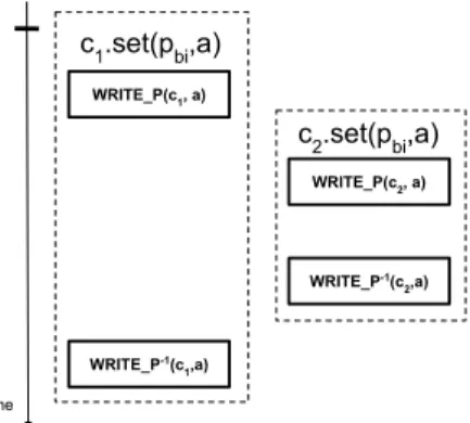
Output models undergo a building process creating a model that grows monotonically (Property 2 and 3). However, during the global computation,
770
there exist some specific cases that may lead to inconsistency. In particular, (i) when having operation invoking a change in more than one element (e.g. containment and bidirectional references), or (ii) updating multi-valued references. For instance, in ATL, elements are newly created and attached to the resource4
(in the match phase), they’re all considered as root elements. Moreover, they’re
775
linked to it through a containment-like relationship. On these terms, and despite Property 4, when moving these elements to their final container (in the apply phase), first, they are removed from the resource, then, they are moved to the new containing element. Similarly, in the case of updating a containment or a bidirectional reference. These operations need to either entirely fail or succeed.
780
3The accessed data is always consistent since no write operation occurs 4A resource can be considered as an index for root elements
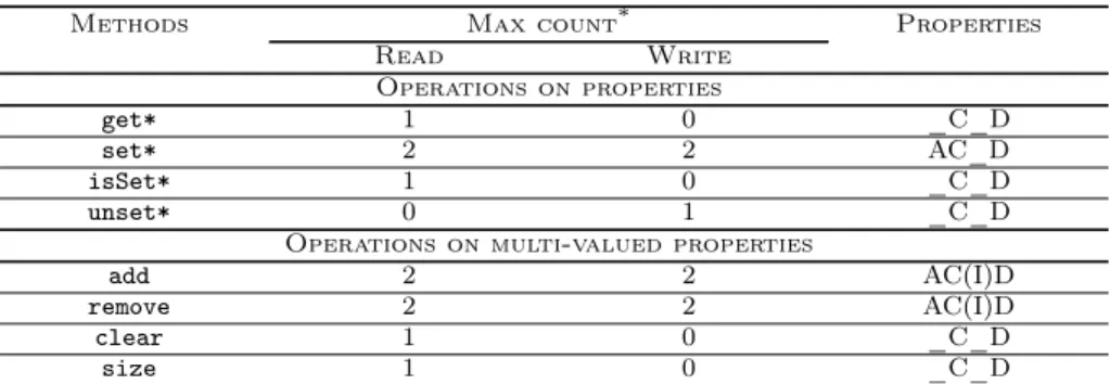
Table 4: Summary of accesses counts of MOF Reflection operations
Methods Max count* Properties
Read Write Operations on properties get* 1 0 _C_D set* 2 2 AC_D isSet* 1 0 _C_D unset* 0 1 _C_D
Operations on multi-valued properties
add 2 2 AC(I)D
remove 2 2 AC(I)D
clear 1 0 _C_D
size 1 0 _C_D
* Note that only max access count is taken under consideration
Table 4 depicts the set of operations in the MOF Reflection API as well as the maximum read/write operation count within a transaction. Note that, operations on full objects such as elements creation are not considered. Finally, the table depicts the ACID properties that need to be fulfilled when the operation is performed during model transformation, in order to guarantee the correctness
785
of the output model. The properties between parenthesis can be relaxed5, while
the others should be strongly preserved.
Beyond lowering data communication over the network, the interest of ATL properties, discussed in this section, extends to reducing the chances of running into concurrent modifications, and thus the Isolation property can be relaxed
790
for some operations. Especially, thanks to Property 2, updates on single-valued properties occur only once in the transformation lifetime. In the case of updates on multi-valued properties, the chances of having concurrent updates are defi-nitely considerable. Nevertheless, in ATL only add or remove operations might run into concurrent updates. The distributed persistence framework should make
795
sure that two concurrent add or remove operations will leave the system in a consistent state6.
As noticed in the properties column, Durability and Consistency are two mandatory properties to be preserved. The correctness of the output results is tied to guaranteeing these properties in every single method. Supposing that
800
the underlying backend guarantees ACID properties at the finest-grained level (single CRUD operation), methods involving updates in more than one element (two-phased commits) need to be atomic, while update operations on multi-valued properties (add and remove) need to be isolated. These methods should execute in two steps, first, the latest value is looked-up, then the property’s value
805
is updated according to the method behavior. However, thanks to the monotonic building process of models in ATL, even if a two-phase commit does not happen
5Supported only in specific scenarios
6It is worth to mention that in MOF, only type, cardinality, and default properties are
natively checked for Consistency. Model constraints, described as OCL invariants, are validated only when invoked.
in the same transaction, the model will eventually be consistent (i.e. we will end up having the same output model). Relaxable properties are depicted between parenthesis. In case one of these methods fails, the system should rollback. In
810
the next section, we show how we guarantee the set of ACID properties on top of NeoEMF/Column.
6. Decentralized Model Persistence for Distributed MTs
In the previous section, we discussed the set of ACID properties that is needed to guarantee a sound and consistent MT in a distributed manner. In this
815
section, we introduce a solution that realizes the aforementioned requirement on top of a decentralized wide-column store.
Storing models in the Cloud is a good solution to break down the complexity in handling VLMs. Due to the limitations discussed in Section 2, we extend, NeoEMF, a multi-layer persistence framework with a decentralized persistence
820
layer called NeoEMF/Column. NeoEMF is EMF-compliant. EMF-based tools would not be aware of the NeoEMF framework, as communications between the tool and NeoEMF are always passing through the EMF layer. We benefit from the built-in features in NeoEMF to alleviate the performance of accessing and storing models for distributed model transformations. In particular, we rely
825
on the on-demand loading mechanism to ensure that only needed elements are loaded, especially when the model is too big to fit in memory. Also, we exploit the different caching mechanisms shipped within NeoEMF reduce accesses to the database and improve the access time of already loaded elements.
NeoEMF/Column is built on top of HBase, a decentralized wide-column
830
store. NeoEMF/Column hides the model distribution from client’s applications. Model access to remote model elements in NeoEMF/Column is decentralized, which avoids the bottleneck of a single access point, and alleviates the alignment between data distribution and computation distribution. NeoEMF/Column is delivered with two stores, the first one is Direct-write and the second one is
835
Read-only. The first store optimizes memory usage by reflecting model changes directly to the underlying backend. And thus, make the new changes directly available to other clients. Inconveniently, all clients have to fetch properties values from the underlying backend at every read operation. In future work, we plan to supply NeoEMF/Column with a distributed notification mechanism
840
to alert clients of changes in model elements.
Model data in NeoEMF/Column is stored using adjacency list. For each node in the graph, a list of vertices adjacent to it is stored. Each row in the table is responsible for storing a model element. This representation has a low storage cost on disk, and the time to access the list of adjacent nodes is constant.
845
In our design, we take advantage of the use of UUID design principle to flatten the graph structure into a set of key-value mappings. More details about the model data mapping can be found in the NeoEMF/Column tool paper [16].