Design of an undervoltage load shedding scheme
for the Hydro-Qu6bec system
Daniel
Lefebvre CCdricMoors
ThierryVan
CutsemResearch Director, FNRS Hydro-Quebec, Division TransEnergie
Complexes Dcsjardins, Tour de I'Est C P 10000 Montreal
(QC),
CanadaUnivcrsity of Liege Dept. of Elec. Eng. and Comp. Sc. Sart Tilman B37 B-4000 Lit-ge, Belgium
lefebvrc.daniel.4@hydro.qc.ca c.moors@ulg.ac.be t.vancutsem @ulg.ac.be
Absfracf-This paper deals with the control logic of an un- dervoltage, closed-loop load shedding scheme aimed at protecting the Hydro-Quebec system against long-term voltage instability. This scheme relies on a set of "if-then" rules whose parameters are determined through combinatorial optimisation, relying on the system dynamic response over a set of scenarios. Preliminary results of the above optimisation technique are given, besides a brief description of the foreseen implementdtion.
I.
INTRODUCTION
There are two lines of defence against incidents likely to
preventively estimate security margins with respect to credible contingencies, i.e. incidents with a relatively high probability of occurrence. Very often, preventive security criteria state that the system should respond in an acceptable way to (N-1)-type incidents, without the help
of post-contingency actions affecting gcnerators and/or loads;
col-rectively: implement System Protection Schemes (SPS) (also referred to as Special Protection Schemes), to face the more severe, but less likely incidents. The latter are typically N-2 or more dangerous disturbances. This paper focuses on corrective control of long-term volt- age instability, driven by load tap changers, generator overexci- tation limiters, switched shunt compensation, restorative loads, and possibly secondary voltage control [I], [Z]. This type of
instability has become a major threat in many systems. While it should be used in the last resort, load shedding
is an effective countermeasure against voltage instability [3],
especially when the system undergoes a severe initial voltage drop that cannot be tolerated for a long time.
As for any SPS. the design of a load shedding scheme is a challenging task in terms
of
number of possible protection settings and (pre- and post-disturbance) scenarios to consider. Even study engineers with a very good knowlegde of their system face this huge complexity problem. Tools are thus needed to help them choosing the most appropriate designs.This paper reports on the use of combinatorial optimisation for the tuning of a closed-loop load shedding controller aimed at protecting the Hydro-Quibec system against long-term trigger system instability:
voltage instability. It is the continuation of the previous pub- lications 141, [SI, [6], considering a new controller structure, new criteria and new dimensioning scenarios.
11. UNDERVOLTAGE LOAD SHEDDING IN THE H Y D R O - Q U ~ B E C SYSTEM
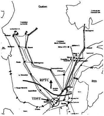
With its long transmission corridors between the hydro generation areas in the North and the main load centers in the South part of the province (see Fig. I ) , the Hydro-QuCbec
(H-Q) system is exposed to angle, frequency and voltage stability problems.
Fig. I, Hydro-Quebec EHV syslem with RPTC and TDST action zones
Besides static var compensators and synchronous con- dcnsers, the automadc shunt reactor switching devices
-
namedMAlS - play an important role in voltage control (71. These devices. in operation since early 1997, are now available in
twenty-two 735-kV substations and control a large part of the total 25.500 Mvar shunt compensation. Each M A E device relies on the local voltage. the coordination hetween substa- tions being performed through the switching delays. While fast-acting MAIS can improve transient angle stability, slower MAIS significantly contribute to voltage stability. MAlS de- vices react to voltage drops but also prevent overvoltages hy reconnecting shunt reactors when needed.
In order to upgrade the reliability of its transmission system,
H-Q has developed over the recent years an extensive defence plan against major disturbances. Besides traditional under- frequency load shedding measures, an extensive generation rejection and remote load shedding scheme - named RPTC
-
has been installed to face transient angle stability problems. The next step of this deployment is the undervoltage load shedding scheme - named TDST - whose implementation is scheduled for the beginning of 2004 (see Fig. I ) .While RPTC is an event-based SPS (due to the speed of angle instability phenomena), TDST will be response-based
[8] (owing to the nature o f long-tcnn voltage instability), re- lying on transmission voltages measured in the Montreal area. More precisey, local voltages will be measured in five 735-kV
substations equipped with MAIS devices and validated through the data acquisition chains of the latter. The measurement sampling rate will be 0.1 second. The average
v of these
local voltages will then be considered, provided that three valid values out of the five have been received.The protection will rely on
V
not only to allow bad data rejection but also to better identify dangerous disturbances. Indeed, while an N-1 contingency (for which no load shedding is allowed) can affect one o f the local voltages, it will have little effect on the average V . Conversely,a
significant dropof
v
is an indication thatan
N-2 or more severe disturbance has occured.The shedding logic will rely
on
the absolute value ofP,
as well ason
the sudden decreasesA V
of
this signal. Innormal operating conditions, the voltage profile of the H-Q
system is maintaind in a narrow range around its nominal value (typically [O.Y8 1.021 pu) while the highest shedding threshold will be around 0.94 pu (a typical value of the critical voltage
in this capacitive system). The A V criterion is used to account for cases where pre-disturbance voltages would be at the upper limit of the above range. The voltage drop
A V
is
computed with respect to a reference V o obtained by taking the average value ofV
overa
sliding time window (of typically 30 s). Assoon as
v
will drop by more 170, the average value ofV
over the last availahle window will be taken as the referenceV".
Invalid values of V are discarded when computing V ' .TDST will act in a pre-defined "load basin", of which it will be allowed to shed at most a certain percentage. The set
of distribution circuit breakers that can he opened is known by the remote load shedding controller also used by RPTC.
By relying on
V ,
the protection is aimed at counteracting system-wide instability. In addition to this, local load sheddingcontrollers will he attached to each of the five substations from which local voltage measurements are taken. Each of these controllers can act on a pan of the above mentioned hassin. Their action will, however. be conditioned to some decrease o f
V .
These local controllers are not considered in the remainingof this paper.
111.
THE
UNDERVOLTAGE LOAD S H E D D l N G LOGlCThe control logic relies on the following:
R I :
if
v
<
Vimin
during d l second.7, shed AP1 M WR2:
if
v
<
VZmtn
during d2 seconds. shed A P , MWR3:
ifV
<
V3"'%"
during d~ seconds, shed A P , MW1 rule allowed to act several times, provided that (at least) one of the above has been already activated:
<
VImin during dI seconds. shed A P T MCb:where the larger -
V ,
the largerAPI
3 rules. each allowed to act once:
RI:
if
Rules
RI
to R3 aim at making the voltage promptly recover once it has dropped below an unacceptable level (e.g. from the customer viewpoint). TheVIm'"
parameteris
set at this level, while the other voltage thresholds are such that :(1) Each rule corresponds to a different level of severity. Corre- spondingly, the load shedding amounts and delays are chosen so that the deeper the voltage drop, the larger thc shedding:
(2)
q n i n
<
~ y i n<
~ ; n i nAP,
>
APl
>
APi
and the shorter the delay:d3
<
d 2<
di ( 3 )Alternative choices may he thought of. For instance, there might be less or more rules, although in the latter case, the computational effort of the optimisation should be kept in mind. Also, the inequalities (2, 3) are not mandatory. although they have been found to work well.
The idea behind rule
R I
is to set upa
controller adjusting its action to the severity of the situation. T h e latter is assessed through the average voltage drop over the time interval d l . Tothis purpose. the load shedding step is given by:
A P I = k AVa,, with AP?'*
5
AP,
5
A P y z (4) whereAVaug
is the average voltage drop :and to is the time at which falls below
VImtn.
Clearly, the largerV;.*"
-v,
the larger A p r .Finally,
API
is discretized as indicated in Fig. 2. to take into account that loads are shed by blocks (when opening circuit breakers).While the main purpose
of R I ,
R2, R3
is to react to a severe voltage drop. the role ofR I
is the final stabilization of theA P J = IC AV,,,
Ap,",
1'""
... .-Fig. 2. Discretization of load shedding
system. In this respect, the thrcsholds of R I and RJ are such that:
'lm*"
<
'Jmin( 6 )
With V,mzn set to a higher value, the risk increases of an
undue load shedding following a large system transient. On
the basis of simulations, it is possible to tune the protection parameters to avoid such false alarms; however, the uncertainty affecting the simulation models must be considered as well. Therefore, to increase the protection security, H-Q has decided to condition the application of R J to the previous triggering of (at least) one of the rules R I to RJ.
Rules
R I , Rz:
RJ
are "concurrent" in the sense that any ofthem can he applied irrespective of the others. However, each rule may he triggered only once.
On the other hand,
R J
is conditioned to the other rules, as explained above, but can be applied repetitively. This yields a closed-loop design since the protection may act several times, each action being based on the measured result of the previously taken actions, and adjusted in amplitude to the system evolution. This closed-loop design guarantees a higher SPS robustness against modelling uncertainties at the dcsign stage.Note finally that by adjusting its action to the severity of the situation, the controller minimizes the risk of overfrequency (and thermal unit tripping) due to excessive load shedding.
1V. OPTIMISATION OF THE LOAD SHEDDING CONTROLLER The methodology used to adjust the settings of TDST consists of two steps [ 6 ] . I n the first step, a set of training scenarios is built, and each unstable scenario of this set is analyzed to determine the minimal load shedding needed. In
the second step, the protection parameters are adjusted in order to approach as closely as possible the optimal sheddings computed in the first step, over the whole set of scenarios. A combinatorial optimization method is used to this purpose. A. Scenario analysis
The first step thus consists in setting up a set of s training scenarios, corresponding to various topologies, load levels, generation schemes, contingencies, etc. Given the load basin that TDST will control, for each scenario, we determine
P: (i = l > ...: s), the minimal amount of load to shed U I U single point in time.
To this purpose. for a given shcdding delay T , the minimal amount Ptm"' of load to shed is dctermined iteratively by in- cremcntal or binary search [ 6 ] . This determination is repeatcd for various values of r ; P: is then taken as the minimum of
the PFin(,) curve.
An example of such a curve is given in Fig. 3 for the Hydro- Quebec system. For the scenario of concern. the best time to shed load is 15 lo 20 seconds (or 35 to 40) seconds after the disturbance. This delay allows the MAIS to trip shunt reactors and hence to increase the network transmission capa- bility, thereby reducing the amount of load to shed. Shedding earlier resets the MAIS by increasing the transmission voltages monitored by these devices. The value of P: is 650 MW.
IICQ}
I
6 shunt reaclor nippings
l800 700 ~ ~ ~ ~ r ( s
600
10 20 30 40 50 60 70 Fig. 3. minimal load shedding vs. shedding delay in a given scenario
B. Statement of the optimization problem in the rules and hence have to be adjusted:
Let us denote by x the vector of all parameters which appear x = [APi APz AP3 dl dz d3 Vzmin V3min
k A P F
AP,""" VImin d,] (7)Given the s training scenarios, the problem is to determine x
such that the following requirements are met:
1) the amount of load shedding must he as close as possible to the ideal value P: determined in the first step;
2 ) all unstable scenarios must be saved (dependability);
3)
no load must be shed ina
stable scenario (security);4) the average voltage must
not
stay belowVIm'"
for This can be translated into an optimization problem: mini-more than some time. mize either the L1 objective:
or the
L ,
objective:max
[P;'(X)
-
P,'+
p , ( x ) ] (9)where, in the t-th scenario, P,"h(x) is the total load power shed by the controller and p,(x) is a penalty term accounting
for the violation of the above requirements. In Eq. (8) (resp.
(9)). thc sum (resp. the max) extends over the unstable scenarios. Thc expression within brackets is expected to be positive since:
.
P;’(x)
> P;:
indeed, more load has to be dropped when shedding in several stcps (as thc controller docs) rather than a single one (as assumed when computing P;). This assertion has been verified in a11 our simulations;.
p , ( x )2
0. For details ahout the choice of the penalties,please refer to [SI. 161.
C. The Brarich-and-Bound approach
The above optimization problcm is complex. Indeed, both
P;” and p , must be determined from time-domain simulations and hence, explicit analytical expressions cannot be estab- lished. Moreover, they vary with x in a discontinuous manner, which prevents from using mathematical programming meth- ods. Finally. multiple local minima are expected. This is why we prefer to resort to combinatorial optimization.
To this purpose. each component
of
x is discretized in afinite number of possible values. The discretization steps are chosen in accordance with the engineering knowledge of the problem (see Section V.A).
Evaluating the L I or L , objectives for a given protection setting requircs to simulate the s scenarios (in order to com- pute the s terms P ~ ‘ ( x ) ~
:
‘
f
+pi(x)). This time-consuming step precludes a brute-force enumeration of all the discrete instances of x.Luckily. a short-cut can dramatically decrease the computa- tional effort. It consists, during the enumeration of the various instances of
x,
in keeping track of 16, the best value of the objective obtained so far. I b is an upper hound on the sought global minimum. Now, as the various scenarios are being checked for a given instance ofx,
the objective function canonly increase. Therefore, as soon as the objective function becomes greater than
I I ,
the scenario enumeration can he broken and the current instance of x ahandoned; otherwise, the value of the objective becomes the new l b . This procedureis outlined in Fig. 4, where x ( j ) denotes the j-th instance of
x
(J=1,. . . : A’).
START R L > lo RREAK L > l b1
BREAK --)END1
Fig. 4. skelch of Ihc Bnnch-and-Bound method
This
significant short-cut of the enumerative search is noth- ing hut an application of the Branch-and-Boutid principle 191.Note that when the load shedding controller only involves rules of the type R I ~ Ra:
Rs.
the optimization problem can be formulated as a tree exploration and an improved hound can be built, from which further speed-up can be obtained with the Branch-and-Bound method [6].When using the L1 objective, the gain i n computing time is expected to he smaller. indeed, due to the additive nature of this objective. a higher number of scenarios have usually to he simulated before the Objective function reaches the I6
value. This is a drawback of the L1 objective. On the other hand. this objective usually behaves more smoothly, i.e. is less sensitive to small changes in parameters 161.
it is easily seen from the above description that the perfor- mance will he improved if
Ib
decreases at an early stage of the search andlor the scenarios with the largest contribution to the objective are processed first. As regards the second aspect, it may be advantageous to dynamically reorder the scenarios on the basisof
their ability to break enumerations, observed at the beginning of the search or in previous optimizations [6].D. Distributed processing
In spite of the effectiveness of the Branch-and-Bound al- gorithm, the computational burden may remain prohibitive, especially when the Lt objective is considered or when the size of the search space to explore is important. Fortunately, the very structure of the problem makes it easy to distribute computations on several “slave” processors coordinated by a
“mastcr” one.
In thefirst scheme to come to mind the master assigns the simulation of a scenario to each slave (as soon as it becomes available) and receives from the latter the value of P;’h and the stablelunstable diagnosis. Enumeration breaks and I6 updates are taken care of by the master. This scheme is efficient in
so far as the time for transferring the data from the master to a slave is small compared to the simulation time, so that the communication overhead remains negligible.
An alternative consists of using each slave to explore a subset of instances
of
x.
In this secondscheme,
as soon asb decreases, the new value must be broadcasted to all the
other slaves.
E. 7ime simulation tools
Detailed long-term voltage instability simulations remain time consuming. This computational burden does not ex- ist with the Quasi Steady-State (QSS) simulation, a well- documented simplified long-term simulation technique [2].
QSS simulation is useful for processing a large search space and taking preliminary decisions, for instance deciding which parameters will he subsequently fixed, to save computing time.
An example of comparison between QSS and detailed simulations is given in Fig. 5 , in an unstable case without load shedding. As can be seen, the long-term behaviour is well captured by the QSS simulation but, expectedly, the short- term transients (taking place over the first 20 seconds) are not
reproduccd. This period of time where voltage and frequency experience large transients has to be simulated in detail in order to properly set the protection parameters.
v
(Pu; 0 . 9 5 0.9 0 . 8 5 0.8 0.75 0.7 b ili
I
0 . 6 5 0 2 0 10 60 8 0 100Fig. 5 . QSS vs. detailed simulation (unstable case)
In this respect, the coupling between full and QSS sim- ulations presented in [IO] is a very interesting compromire hetween efficiency and accuracy. The idea is to simulate the short-term period using detailed simulation and, once the transients have died out, to switch to QSS simulation, the latter being initialized "out of equilibrium".
V. RESULTS A. Training scenarios and criteria
urations. summarized in Table I.
The study reported in this paper involves 22 system config-
TABLE I
SYSTEM CONFIOUKATIONF CONSlDEREU IN T H E T R A I N I N G SCENAKlOE
__
conA- ;urntion A R C D E F G H I J K L M N 0 P Q R S T U V__
735-kV lines >ut of service 0 I 1 1 1 I 1 4 4 3 3 3 3 1 I 1 3 0 1 I 4 3 mber of iynChrOnOUS condensers 6 6 8 8 1 8 7 8 7 8 1 8 1 1 7 1 1 6 8 8 8 7 MAlS devices 6 6 6 6 4 I O 6 6 4 10 6 10 6 3 4 4 5 6 6 6 6 6__
-
-
oad active power exponent I I I 1 1 I I I I I I I 1 I I 1 1 1.3 1.3 I .3 1.3 1.3_ _
-
Table I1 details the 38 scenarios finally selected. They involve N-I, N-2 and N-3 contingencies, respectively. In
accordance with the standard operating rules. the systcm is stable following any N-l incident. The MAIS devices can bc uscd to this purpose.
TABLE II DESCKII'TION OF T H E 38 T K A l N l N C SCEKAKIOS
i
G
-
I 2 3 4 5 6 7 8 9 I O II 12 I 3 14 15 16 17 18 19-
-
:ani. A A R A R R B C C S C D D E N T D F G-
-
-
ncid. N-l N - l N-2 N-2 N-3 N-l N-2 N-l N-2 N-2 N-2 N - l N- I N-2 N-2 N-2 N-2 N-l N-2-
type-
32 37-
:ant G 0 P H H I U H U J J K J V L L U M Q-
-
a
'ype N-2 N-2 N-2 N-l N-l N-2 N-2 N-2 N-2 N ~ l N - l N-2 N-2 N-2 N - l N- 1 N-2 N-2 N-2-
-
P; (MW) 300 I00 300 0 0 300 1450 1200 650 0 0 300 X M ) 600 0 0 U 500 0-
The training set includes 16 stable scenarios in order to train the protection not to act in stable cases. In the 22 unstable scenarios, the minimal load sheddingP:
has been determined as outlined in Section IV-A. The values. computed with anaccuracy of 50 MW, are given in Table 11. In this study, load shedding is shared out between 10 locations, each load being decreased proportionally to its initial value. As can be seen from Table 11, the P: values range rather uniformly in the [lOa 14501 MW interval, between marginally and severely unstablc cases.
Requirements 1 to 4 of Section IV-B have been taken into
account. In accordance with Hydro-Quebec planning rules, the 3rd requirement has been amended by allowing some (hopefully small) load shedding to take place after
a
stable hut severe incident. The N-2 scenario No 19 is concerned. The latter is handled as an unstable scenario with P: = 0 in (8) and (9). This leads to finally processing s = 22+
1 = 23scenarios. As regards the 4th requirement, the average voltage is not allowed to stay below VI"" = 0.94 pu for more than 15 seconds.
B. Search spaces
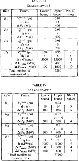
Tables I11 and IV detail the two search spaces considered in this study, referred to as SPI and SP2, respectively. The main
difference between them concerns
the
numberof
unknowns to determine. In SPI, the parameters of rules R I , R? andR3
are fixed to values suggested by preliminary trial-and-error simulations. Hence, the parameters to he optimized (indicated with hold font) are those associated with the R I rule.On the other hand, thc purpose of SP2 is to let the methodology find the best parameters of rules R I ,
Rz
and RBas well. The exponential complexity of the combinatorial op- timization makes it nonetheless necessary to limit the number
TABLE 111
SEARCH SPACE I
TABLE I V
SEARCH SPACE 2
1 Rule I I L w n I Umrr I Nb.of I
of unknowns as well as the values tested for each of them. In
this respect, the thresholds VZmi“ and
VJmin
have been chosen from the observation of the very first voltage drops (after the disturbance occurrence). They havc also been chosen to that each ruleis
optimized froma
significant number of scenarios. Finally, the size of the search space has been further reduced by “linking” the delays d l , dl and d3 as indicated in Table IV.The total number of instances of x is given in both tables. The only considered designs are those satisfying inequali- ties (2), (3) and (4). Taking into account that each combination has to be tested over 23 scenarios, these figures confirm the huge complexity of the combinatorial optimization.
C. Computing tools
As of writing this paper. tests with detailed simulation are
under progress. Therefore, we present hereafter the results of
a
preliminary study using QSS simulation.To speed up computations, thc dynamic reordering tech- nique mentioned in Section IV-C has been used.
Finally, when optimizing the
L 1
objective from SP2. the ~computations have been distributed over 4 PCs. according
to
the second scheme of scction IV-DD.
Results arid discussimTable V shows. for each search space and each Objective, the optimal value found for the various parameters and the value of thc corresponding objective. For information only. the value of the other (non optimized) objective is given in parentheses underneath the first one. Let us emphasize that all four requirements of Section IV-B are met in all designs of Table V.
TABLE V
OPTlMlZATlCJN RESULTS
As can be seen, the performances of the controllers found from the two search spaces are the same when the L , objective is considered (see 2nd and 4th columns of the table). On the other hand, optimizing the L L objective from SP2
allows to find
a
better design (see 3rd and 5 t h columns). This result indicates that, while the primary objective of rulesR I
toRB
is to make voltages promptly recover, they are also useful to improve the controller performances in terms of shed amounts. The final choice between the two objectives will be made from the results of detailed simulations.Figures 6 and
7
show two typical time evolutions ofv
for one of the obtained designs.In Fig. 6, the behaviour is typical of a “traditional” under- voltage load shedding scheme. In the first scconds following the occurrence of the disturbance, several rules are activated to shed an important amount of load, in order
v
to be brought back above 0.94 pu, The final stabilizationis
then guaranteed by MAIS devices and theR I
rule.The situation is different in Fig. 7: although
v
falls belowVImin
and Vzmzn just after the disturbance, the controller takes advantage of the MAIS devices, which make V recover above 0.94 pu. Once the voltage decrease resumes, the controller hasto wait for rule R I to shed 400 MW; thcn, it relics on rule
R I
to adjust its action to the severity of the situation. This allows the total load shed (700 MW) to he very close to the target value(P:
= 650 MW).\,,mi"
\T2"
\p"
n 50 I W 150 zoo 250 300 350 400 450
Fig. 6. Time evolution of in scenario 26
SPI
L ,
1
L16 shunt reactor trippings by MAIS
SP2 L ,
I
1.1 sheddine of 3'100 MW-1
enumeration B&B approach Gain / I V F " shedding of 400 MW 0.92 t (S) 50m o
150 n.931
Ij
nFig. 7. Time evolution of V in scenario 28
7773 101322 518242 331479
16 I.? 18 5.4
Table VI compares the total number of simulations required
to design the controller from the two search spaces. These figures confirm that optimizing the L l objective requires more simulations and hence is more time consuming. The gain with respect to a brute force enumeration is much more important in the case of L,, as discussed in 161.
However, the optimization of L 1 from SP2 shows an in- teresting result: sharing out the search space between several processors (which was not done for SP1) allows to break more enumerations and hence reject a larger percentage of (useless) designs. Indeed, with 4 processors working in parallel, lower values of I b have been discovered sooner, and broadcasted to
the other processors. From the computing time viewpoint, this adds to the gain naturally obtained from parallel computations. These two speed-ups cumulated bring a n overall gain i n
computing time of 15.
VI. CONCLUSION
This paper has described some characteristics of TDST, an undervoltage load shedding scheme scheduled for implemen- tation in the Hydro-QuCbec system by the beginning of 2004. The emphasis was on the control logic. Obviously, many other practical aspects, essential for the reliability of such a system
protection scheme, have not been considered here.
TDST will rely on four if-then rules. Three of them aim at making the average voltage promptly recover above some admissible level, and will make up the first line
of
defence against voltage instability. Conditioned to the previous trig- gering of these rules, the fourth one is allowed to act several times and to adjust its action to the severity of the situation. thereby yielding a robust closed-loop protection.The combinatorial optimization (Branch-and-Bound)
methodology previously proposed by the authors to optimize the parameters of the above rules, has been applied Io this new structure, using a new set of dimensioning scenarios. The results of a preliminary study have been presented in
this paper. Tests with detailed simulations are under progress. Distributed processing, as outlined in this paper, is essential to keep the optimization approach tractable while investigating a sufficiently large search space for the protection parameters.
Obviously, the final tuning of TDST will have to take into account several other aspects, such as the coordination with the existing RPTC.
The method is already useful to assist Hydro-QuChec en- gineers in the highly combinatorial and multi-faceted task of adjusting TDST parameters. It will also prove useful for updat- ing thc protection parameters, for instance when transmission system reinforcements will come into effect.
REFERENCES
[ I ] C. W. Taylor, Power System Voltage Stability. McGraw Hill. EPRl Power System Engineering series, 1994
[21 T. Van Cutsem. C. Voumas, Voltage Stability of Electric Power Systems.
Boslon. Kluwcr Academic Publishers, 1998
[I] C. W. Taylor. "Cancepls of undervoltage load shedding for voltage stability", IEEE Trans. on Power Delivery, Vol. 7, pp. 480-488. 1992 141 C. Moors, D. kfebvre. T. Van Cutsem. "Load Shedding Controllers
Against Voltage Instability: a Comparison of Designs". Proc. of the IEEE Power Tech Conference. Pono (Panugal). 2001, ISBN 0-7803-7140-2
[51 C. Moors. D. Lefebvre, T. Van Cutsem. "Design of load shedding schemes against voltage instability". IEEE Power Engineering Society Winter Meeting. Singapore. 2000
[ 6 ] C. Moors. On the Design of Load Shedding Schemes against Voltage
Instability in Electric Power System. PhD thesis, University of Lilge. Fuc. of Applied Sciences, October 2002
(71 S. Bemard, G. Trudel, G. Scott, "A 735-kV shunt reactors automatic switching system for Hydro-Qu&c network". IEEE Trans. on Power System, Vol. 11, pp. 2024-2030, 1996
[SI ClGRE Working Group 34-02-19, System Protection Schemes in Power Networks. ClGRE publication, 2001
[9] W. S. Cook, W. H. Cunningham, W. R. Pulley Blank. A. Schnjver,
Combinatorial Optimization, Wiley-Interscience, 1998
[IO] L. Loud, P. Rousreaux, D. Lefebvrr, T. Van Cutsem. "A time-scale decomposition-based simulation tool for voltage stability analysis", h o c . of the IEEE Power Tech Conference, Pono (Ponugal), 2001, ISBN 0-
7803-7 140-2.