Rankine cycle for waste heat recovery on commercial trucks:
approach, constraints and modelling
N. Espinosa
1, L. Tilman
2, V. Lemort
2, S. Quoilin
2, B. Lombard
1 1: Volvo Powetrain France, 1, Avenue Henry Germain 69802 Saint Priest2: University of Liège, Thermodynamics laboratory, Campus of Sart Tilman, Bât 49, B-4000, Liège, Belgium
Abstract: With increasing oil price and growing interest in cutting green house gases emissions, waste heat recovery techniques appear as a very promising path to enhance engine thermal efficiency.
Thermoelectricity and Rankine cycles are two possible ways to recover thermal energy. The Rankine cycle shows the highest potential due to its higher cycle efficiency in comparison with the current state-of-the-art thermoelectric materials intrinsic conversion ratio. This paper will focus on the Rankine cycle system.
The first part of the paper lists and describes the constraints of a heat recovery Rankine cycle system associated to a long haulage truck: limitation of heat available in the heat source, vehicle heat rejection constraints, safety and environmental issues for the working fluid, and backpressures occurring during the heat recovery process.
The second part of the paper presents a 0-D simulation model of a Rankine cycle system. It is shown how the model can be used to compare the performance achieved with several working fluids. Moreover, basic thermodynamic limitations of the system are underlined. Conclusions are drawn concerning the limitation of using only thermodynamic simulations.
The performance of the condenser (and its influence on the overall performance) has been investigated more in details, which is shown in the third part of the paper. This was carried out based on a 1-D simulation model of the condenser. Influence of the condenser size and ram air effect are discussed, and the impact on the Rankine cycle is assessed.
Keywords: Waste heat recovery, Rankine cycle, modelling.
1. Introduction
For commercial vehicles, fuel economy is one of the main drivers of the powertrain development to design competitive trucks. Indeed, in France, for a typical long haul truck owner, fuel consumption is the second more important cost (23 %) after salaries [12]. Furthermore, major technical evolutions in the commercial vehicles powertrain
were done to comply with emission regulations during the last decade, and the next regulation (Euro VI – 2014) will regulate pollutants to near zero. However, other emissions such as carbon dioxide could be later regulated as it is the case in Japan, pushing even more technologies for powertrain efficiency enhancement.
Rankine cycle Waste Heat Recovery (WHR) systems are promising ways to improve engine efficiency for long haul trucks that spend a small amount of time in transient operations.
A basic WHR Rankine cycle system is made of a pump circulating the liquid working fluid from the low pressure to the high pressure of the system, an evaporator producing a working fluid vapour when recovering the wasted heat, an expansion machine (or expander) producing the usable work from this vapour by expanding it to a lower pressure level, and a condenser bringing the vapour back to the liquid state before entering the pump back again (see Figure 4). The implementation of Rankine cycles for recovering heat in mobile applications have been studied for years and relevant examples can be found in the literature [1], [2]. Mack Trucks designed a Rankine cycle on a commercial truck using a Fluorinol mixture as working fluid during the 1970’s. More recently, systems including modern internal combustion engine (ICE) constraints were reported by Honda [3] and BMW (the “Turbosteamer”) for passenger cars [4] and Cummins [5] for commercial trucks. All those systems enable to decrease the fuel consumption up to 10 %. Some publications dealt with Rankine cycle modelling results [13] [14], the first one focused on light duty vehicles and the second did not use real commercial vehicle duty cycles. This paper focuses on the commercial vehicles constraints and modelling tools for waste heat recovery Rankine cycle systems. The reflexion is based on a typical European commercial truck highway usage. Along the paper, 0-D and 1-D simulation tools are presented and illustrate the impact of those constraints on the Rankine cycle system and on its limits.
This paper highlights the constraints inherent to commercial vehicles and their influence on the Rankine cycle system design and performance.
2. Commercial vehicle waste heat recovery constraints
2.1 Heat sources
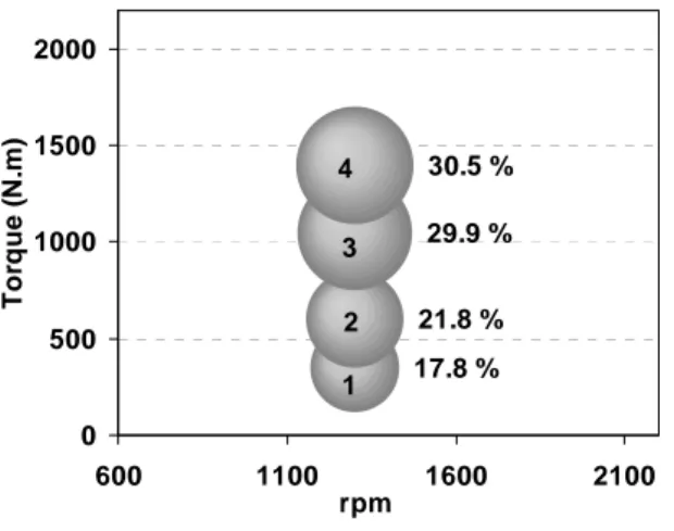
Four heat sources are recoverable on a truck: the charge air cooler (CAC) gases, the engine coolant, the exhaust gas being recirculated (EGR) and the tail pipe exhaust gases. Teng et Al. [6] showed that EGR and exhaust gases are the most interesting heat sources recoverable due their high exergy value. On road, a commercial long haul truck shows a stationary behaviour due to its flat highway rolling most of the time. The engine is operating at mid-speed and between 30 and 60 % of the full load as illustrated in Figure 1.
30.5 % 29.9 % 21.8 % 17.8 % 0 500 1000 1500 2000 600 1100 1600 2100 rpm Tor que ( N .m ) 1 2 3 4
Figure 1 : engine operating points and time-weighting factors on a predominantly flat motorway (Paris-Lille road, cruise speed 90
km/h, engine 11 liter US’07 385 hp). The particular low load rolling and the good diesel engine efficiency are responsible for low exhaust temperature levels typically around 300 °C (Table 1). On an exhaust gas recirculation (EGR) engine, the temperature is around 100 °C higher but the recirculated mass flow rate is lower by more than 70% compared to the exhaust gases mass flow rate. The latter flow rate depends on the strategies employed by the engine manufacturer to reduce nitrogen oxides emissions (NOx).
High EGR rates strategies can be employed, as mentioned by Teng et al. [14] which can make the EGR a very attractive heat source for WHR. However, there is a current trend to increase the efficiency of the NOx aftertreatment system, which means that high EGR rates (that reduce the engine efficiency) are becoming less attractive for the manufacturers.
As those heat sources are finite, the Carnot efficiency can not be used to describe their maximum potential. Indeed, when they are recovered, their temperature decreases. The maximum thermal efficiency definition given in [7] is more appropriate for these heat sources as it integrates the Carnot cycle along the heat source
(°C) (kg/s) 1 300 0.13 2 312 0.14 3 333 0.17 4 330 0.22 Engine point Exhaust mass flow rate Exhaust temperature
Table 1 : exhaust temperature and mass flow rate on four typical engine operating points of a commercial truck – the weighting factors are
presented in Figure 1.
temperature decrease. This definition corresponds to a reversible engine running with a finite heat source and defined by:
c h h c h c th,max
T
T
ln
T
T
1
T
T
1
η
−
−
=
(1)The theoretical maximum efficiency of a finite heat source at 300 °C is only 25 % whereas it is 45 % for the Carnot efficiency (Figure 2). When considering a non-ideal Rankine cycle operating with the refrigerant HFC - R245fa fluid (1,1,1,3,3-Pentafluoropropane) and recovering the exhaust gas energy with a finite gas source (0,2kg/s), the efficiency is further decreased to a 10 % value due to a more reasonable cold source (40 °C), thermodynamic properties of the fluid and component efficiencies (see section 3.3).
Figure 2 : comparison between Carnot efficiency, maximum thermal efficiency for a
15 °C infinite cold source and an R245fa thermodynamic Rankine cycle (40 °C finite
2.2 Constraints on the rejected heat
As aforementioned, engine exhaust gases are the most interesting heat source to be recovered due to their higher exergy content. A system recovering both EGR and exhaust gas line (after turbine) can also be considered but complicates the WHR system and increases its cost. Since all engines do not use EGR, this paper will focus on a pure exhaust WHR system.
Adding a WHR system increases by more than 25 % the need for heat rejection on the truck because the condenser of the Rankine cycle needs to be cooled down and the heat to power conversion efficiency is low (between 10 and 20 % depending on the temperature level).
Heat can be rejected directly to the air (direct cooling system) or indirectly to an intermediary fluid (indirect cooling system). The latter is then cooled by air by means of an additional heat exchanger (a radiator in front of the truck for example).
The direct air-working fluid condenser shows the higher potential due to a lower condensing pressure but the additional amount of working fluid required can be important and problematic for certain fluids (high global warming potential and inflammable fluids). The indirect cooling system enables a small Rankine cycle loop but decreases the efficiency by integrating a second temperature difference in the additional heat exchanger. The direct air condenser can be considered as the most promising heat rejection system due to its higher efficiency. This is probably why it has been preferred in previous studies [1] [2] [3]. However, it brings significant packaging issues for the Rankine system.
Since the engine operates most of the time at mid-speed, mid-load (vehicle driving at 80-90 km/h), the ram air speed is preferred to cool the Rankine cycle. The direct air condenser can be placed separately from the existing cooling system, for example on top of the cabin roof. The major drawback is the aerodynamic penalty for the truck as the air speed is important. It can also be placed behind the cabin. In that case, a fan is required for the air condenser because the vehicle ram air speed is almost zero. The power consumption of such fan can rapidly increase (usually as the square of the flow rate), reducing the interest of this configuration.
The air-cooled condenser can also be placed in front of the existing cooling system. This implies no (or few) aerodynamic impacts. The drawback of this solution is the impact on the existing cooling system due to a higher air temperature coming in the charge air cooler (CAC) and the
decrease in air speed on the existing cooling circuit. In that case, the rejected power from the Rankine cycle is directly linked to the cooling system behaviour and sizing.
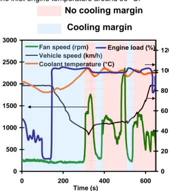
Commercial truck cooling systems are sized for the worst road scenario that could be experienced: the truck is fully loaded (40 T), runs at a very low speed climbing a slope (no ram air) and ambient temperature is very high (40 °C). The fan is then sized in order to provide the minimum air maintaining the coolant outlet engine temperature below the boiling point (<110 °C) - On a flat road (low engine load) at 90 km/h, the fan is disengaged (the fan rotates due to aerodynamic drag and ram air alone is sufficient to cool down the engine. A thermostat regulates the coolant flow rate in the radiator to maintain the inlet engine temperature around 90 °C.
0 500 1000 1500 2000 2500 3000 0 200 400 600 Time (s) 0 20 40 60 80 100 120 Fan speed (rpm) Vehicle speed (km/h) Coolant temperature (°C)
Cooling margin
No cooling margin
Engine load (%)Figure 3 : existing cooling margin zones for a long haul truck before and during a road
slope.
Figure 3 illustrates the fan regulation: when the truck starts to climb uphill (at t = 180) the engine load increases from relatively low to full load to maintain vehicle speed), which increases the coolant temperature up to 100°C. The coolant flow rate in the radiator is increased to maintain its temperature. Since this is not sufficient to maintain the coolant temperature, the fan is engaged.
For the Rankine cycle system, the heat rejection is possible when the balance between the power recovered by the Rankine cycle system and the additional fan power consumption remains positive.
Most of the time in a vehicle life, the fan is not engaged (or at a low speed as trained by the ram air). This means that a cooling margin exists for the Rankine cycle system. This cooling margin zone is illustrated in Figure 3. The cooling margin exists for relatively flat roads (engine load at about 40 % and vehicle speed at 90 km/h). Transients have to be considered carefully to prevent the fan engagement.
To summarize, a direct air Rankine cycle system is a promising solution to maximize the Rankine cycle efficiency. This air condenser can be placed in front of the existing cooling system to minimize aerodynamic penalties but the Rankine cycle has to be stopped before the fan engagement.
2.3 Energy usage
The net power generated by the Rankine cycle is of mechanical type. This mechanical power can be directly supplied to the engine shaft by means of a belt or a gearbox, or be used in combination with a generator to produce electricity.
The mechanical coupling depends on the selected expander technology. Volumetric expander (scroll, screw, piston, etc.) show a relatively low rotating speed, which allows direct coupling with the engine shaft through a belt or gears. Turbomachines on the other hand show a very high rotating speed, which makes the use of an intermediate gearbox necessary.
When a generator is used to produce electricity, the control of the expander can be achieved by varying its speed and/or bypassing the working fluid. The onboard electrical network on a long haul truck consumes about 1 kW electrical power in average with peaks up to 4 kW, which is lower than the output power of the Rankine cycle. (see 3.2). As a result, introducing a Rankine cycle system with a generator implies to electrify some vehicle and engine auxiliaries, such as the cooling fan and/or the air-conditioning compressor that are huge consumers.
2.4 Working fluid selection
The use of a particular working fluid is explained by its ability to extract heat at a low temperature level. Indeed, each working fluid thermodynamic characteristic should be adapted to the heat source (see 3.2). Various working fluids have been used on automotive applications and show various thermodynamic potentials: ethanol and water were used by BMW [4], R245fa by Cummins [5] or fluorinol mixtures by Mack Trucks [2].
For commercial truck, the low flammability level is a major concern especially for a system using an air-cooled condenser. Hence, alcohols and
hydrocarbons are arguably not the best candidates despite of their good thermodynamic efficiencies. Instead, refrigerants are usually good candidates and are already used for air-conditioning systems. They are generally not dangerous and compatible with materials. They do not freeze, which is the major concern with water. However, the current generation of refrigerant called HFC shows a high global warming potential (950 - 1070 for HFC-245fa [19]), which means that their use could be limited or banned in the near future. The new HFO -1234yf which replaces the R134a for mobile air conditioning is part of a new fluid generation called HFO. It has a very low global warming potential (GWP) around 4 [20]. HFO fluids with higher critical temperature than the HFO – 1234yf could be promising for the use in Rankine cycles on commercial vehicles.
2.5 Backpressure impact
The presence of an evaporator on the exhaust line will have a negative impact on the engine backpressure. As the evaporator is size-constrained and should stay efficient to extract as much heat as possible from engine exhaust gases, it should be designed to limit the backpressure. Since heat rejection is not possible on high loaded engine operating points, a bypass is also a solution to avoid too large backpressures when the Rankine system is not running. Such typical design strategies have already been applied for thermoelectric generators [15].
3. Thermodynamic considerations 3.1 Modelling the Rankine cycle
A 0-D simulation model is necessary to understand the thermodynamic limits of such a heat recovery system.
The thermodynamic model developed under “Engineering Equation Solver” (EES) presented in Figure 4 associates a simple modelling of the pump and the expander by means of an isentropic efficiency, with three zone models of the evaporator and of the condenser. The system is modeled under EES and is mainly inspired from previous works on Rankine cycle from Quoillin [21] and Lemort [16]. More sophisticated models mixing 0-D and 1-D heat exchanger models are reported in the literature by Duparchy et al [8]. The evaporator and the condenser are modelled by assuming that they can be fictitiously divided into three heat exchangers (3-zone model) associated in series and characterized by a pure counter-flow arrangement (Figure 4). These heat exchangers correspond to the liquid zone (L), the
vaporization zone (TP) and the vapour superheating zone (V). L ev out g T , , , Tg,in,ev,V L ev in wf T , , , Twf,out,ev,V pp in wf
T
, , ex out wf T , , ex in wfT
, , V cd in wf T , , , L cd out wf T , , , pp out wf T , , L cd in a T, , ,T
a,out,cd,V Pump Evaporator Expander CondenserFigure 4 : Rankine cycle overall model The simulation software being an equation solver, inputs can be set as outputs and conversely. Generally, in sizing-oriented simulations, the vapour superheating at the evaporator exhaust is imposed, as well as the temperature pinch point in the evaporator and the condenser. In this case, the required heat exchange area is calculated by the model.
The selection of the pinch point results from a trade-off between the cost of the heat exchanger, its size and its performance. By considering the values typically achieved in refrigeration heat exchangers, this pinch point is fixed a priori to 10 K, keeping the order of magnitude typically achieved in vapour compression refrigeration systems. This value is further analyzed for the condenser with the 1-D simulation tool. Enthalpies in EES are automatically determined as function of parameters such as pressure, temperature, fluid quality, entropy. In this model, efficiencies are not chosen as inputs of the model. Instead, a minimum pinch point is fixed. It is defined by : ) ; ; ( , , , , , , , , , , , , , , , , , , V ev out wf V ev in g L ev out wf TP ev out g L ev in wf L ev out g pinch T T T TΔT =MIN− T −T − (2)
The pump is modelled by an isentropic efficiency that is supposed constant and fixed at 70 %. It is assumed that the pump flow rate is regulated in such a way to maintain the imposed superheating at the expander inlet.
The modelling of the condenser is based on the following hypothesis: the condensing temperature is imposed at 30°C which means that the condenser is designed and controlled to maintain this temperature. This temperature ensure a realistic pinch point if ambient temperature is taken as the cold medium (engine coolant is not taken as cold source). The liquid subcooling is
neglected. Practically, this parameter depends on the amount of fluid charged into the cycle [21]. 3.2 Application
This 0-D tool enables to analyse the behaviour of various fluids for a given heat source (temperature and mass flow rate fixed).
When considering a recovery on the engine exhaust gases, it is proposed to study three typical fluids encountered in the literature: water, ethanol and HFC-245fa. As illustrated in the T-s diagram (Figure 5), those fluids have various critical temperatures and latent heat of vaporization. -50 0 50 100 150 200 250 300 350 400 0 2 4 6 8 Entropy (kJ/kg/K) Temp e rat u re (° C) Water Ethanol R245fa
Figure 5 : T-s diagram comparison between three typical fluids.
Evaporative pressures and condensing temperatures are two typical parameters that can be studied within the 0-D tool.
The assumption considered in this paragraph are : a 70% isentropic efficiency for the expander and the pump, a 10 K pinch point at the evaporator and a 30 °C minimum condensing temperature, As shown in Figure 6, the net power produced by the Rankine cycle usually increases with the evaporative pressure for a fix condensing pressure. Hence, the evaporative pressure giving the maximum net output power is the critical pressure for ethanol and HFC-245fa. The superheating used should be kept at its minimum value as concluded by Mago et al. [17]. This is characteristic for fluids with a low critical pressure compared to the hot source [18]. For water, the behaviour is rather different as it is a wet fluid (the vertical saturation vapour line has a negative slope). The superheating is needed not to condense the fluid after the expansion which could damage the expansion machine (especially for an axial turbine). This superheating is limited by the inlet gas temperature.
0 2 4 6 8 10 12 0 20 40 60
Evaporative pressure (bar)
Ne t p o w er r e c o ve re d (k W) Ethanol R245fa Water
Figure 6 : influence of evaporative pressure on net power output for three typical Rankine
cycle working fluid on engine point 3 (Figure 1) - 30 °C condensing temperature – pump
and expander efficiencies set to 0.7. When a superheating is needed, the recovered energy can not be used to preheat the fluid which limits the evaporating pressure. This explains why the water evaporative pressure is limited in Figure 6. As a result, the net power recovered levels off to 7 kW. As ethanol is a more isentropic fluid (vertical saturation vapour line), a high superheating is not necessary which enables an increase in pressure and in net power recovered. This first results obtained in Figure 6 only take into account heat sources. Real components would change this conclusion. For example, water was considered at 30 °C condensing temperature which means at an under atmospheric pressure level. A 100 °C condensing temperature would be rather profitable. The same reasoning can be applied for ethanol which condenses at 80 °C. Furthermore, when considering a reciprocating expander used for the Rankine cycle, the volumetric expansion ratio should be considered instead of a simple pressure ratio as it integrates the density of the fluid. This volume ratio is defined as the ratio between the volumetric flow rate at the expander outlet and inlet. As the volume ratio depends on the properties of the fluid, it better gives an idea of the expander size used.
Taking into account those considerations, the net work recovered is given as a function of the volume ratio in Figure 7. R245fa enables the highest recovered work for a fixed volume ratio. However, the rejected power is higher for R245fa as it enables a higher heat extraction from the heat source as shown in Figure 8. As a result, a simple 0-D considerations gives a first analysis on the performance and on working fluids that should be used for a given heat source. When comparing the three fluids studied in the literature, R245fa seems the most attractive despite its higher heat rejection rate. A 1-D approach should be used to
consider component size as well as sensitivity to external parameters. 2 2.5 3 3.5 4 4.5 5 5.5 6 6.5 7 0 20 40 Volume ratio N e t p o we r r e c o vered ( W ) Water R245fa Ethanol
Figure 7 : Net power recovered by the Rankine cycle on the engine point 3 as a function of the volume ratio for water, R245fa and ethanol
working fluids. 2 7 12 17 22 27 32 37 42 47 52 0 20 40 Volume ratio R e je ct ed p o w e r ( k W ) Water R245fa Ethanol
Figure 8 : rejected power by the Rankine cycle on the engine point 3 (Figure 1) as a function
of the volume ratio for water, R245fa and ethanol working fluids.
4. 1 –D simulation
A 1-D condenser model has been developed under GT-Power® to investigate more in details the condenser component. The GT-power® code uses the Navier-Stokes equations in discretized volumes. Conservation is done for the mass, the energy and momentum between each volume. Transient and steady state simulations can be done. This paper will focus on steady state simulations.
4.1 Condenser modelling
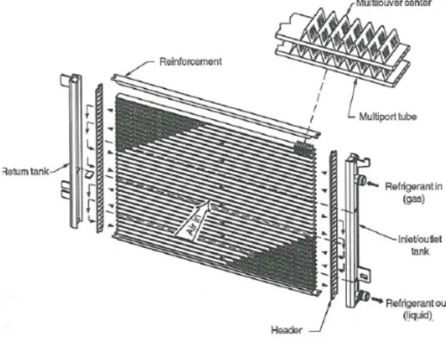
The condenser model is based on existing automotive parallel flow air-conditioning condensers installed on a commercial truck (see
Figure 9). As those condensers are sized for a good cost/performance ratio this technology is attractive for an automotive Rankine cycle.
Figure 9 : typical louvered parallel multiflow condenser used in automotive
air-conditioning [ 9].
The condenser modelled is a parallel flow with louvered fins on the air side. The main assumptions in this model are the followings: the refrigerant passes were not taken into account for simplicity, pressure drops on the refrigerant side were not considered, channels in the tube were not modelled, the fluid distribution is considered as uniform and longitudinal conduction is not modelled.
On the gas side the Chang and Wang correlation [10] was used to define the heat transfer coefficient and the Colburn factor for the pressure drop specification for the condenser fin louvered geometry. The pressure drop and the heat transfer coefficient are then integrated along the condenser in a Fortran user model implemented in GT-Power®. The latter user model enables to define the heat rate between the air side and the wall for the particular geometry used.
Figure 10 : Rankine cycle parallel flow condenser model implemented under
GT-Power.
On the refrigerant side, Dittus-Boelter [11] correlation for smooth pipes is used for the desuperheating and subcooling zone whereas Shah [11] is used for the two-phase zone. The
latter correlation is found as relatively appropriate for low mass velocities.
This model is validated with a maximum difference of 10 % compared with test data for an R134a air-conditioning condenser (Figure 11).
0 5 10 15 20 25 0 2 4 6 Air speed (m/s) H e at t ra n sf er e d ( k W ) Model data Test data
Figure 11 : parallel flow GT- Power condenser model validation on a R134a air –conditioning
commercial truck condenser. 4.2 Condenser study
As the 1-D condenser model is based on existing correlations, it can be considered as predictive. As a result, it is used to size or to investigate the impact of external parameters.
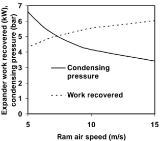
When the speed of the truck decreases, the ram air available in front of the truck will also decrease. The impact on a Rankine cycle global model done under GT-Power® is presented (Figure 12). This overall GT-Power® Rankine cycle model considers a 70% isentropic efficiency for the pump and the expander, an infinite evaporator and the condenser presented in 4.1. The condenser considered in calculation has a 0.25 m² front surface and it is 16 mm thick. Engine point 3 exhaust gases conditions are used as inputs to the simulation (see Table 1). A decrease in ram air speed increases the condensing pressure of the cycle for a fixed cycle condition (Figure 12). The evolution is not linear as the condenser tends to be saturated when the air speed is very important. Conversely, when the air speed goes below 10 m/s the recovered power drops significantly. The cycle efficiency remaining approximately the same, this power drop is mainly explained by a lower heat rejection that is a lower heat extraction at the heat source.
The packaging limited in front of the truck sets the condenser heat transfer surface. As a result, the overall heat transfer coefficient U .A is limited. To ensure an amount of heat transferred within the limited packaging the temperature difference between the two fluids should increase (see equation 3).
0 1 2 3 4 5 6 7 5 10 15
Ram air speed (m/s)
E x p a n d e r w o rk re c o v e re d ( k W ), condensi ng pr essur e ( b ar ) Condensing pressure Work recovered
Figure 12 : influence of ram air speed on the HFC – R245fa Rankine cycle condenser pressure and the expander work recovered at
15 °C ambient temperature. 0 20 40 60 80 100 120 140 0 10 20 30 40 Heat transfered (kW) Te m p er at ur e ( °C ) R245fa air ~40°C
Figure 13 : Temperature within the condenser as a function of the heat transferred for air and R245fa. Results based on a 5 m/s air inlet
speed. The pinch point is around 40 °C. The minimum temperature difference defined as the pinch point illustrates this in Figure 13. It is around 40 °C. This high value is explained by the limited place in front of the truck.
DTML
A
U
Q
=
.
.
(3)In the case simulated, the outlet air temperature is 40 °C. This temperature would impact the truck fuel consumption. For a commercial truck, above 40 °C CAC inlet air temperature, a 10 K increase in temperature implies a 1 % fuel consumption penalty. This is mainly explained by a lower inlet air engine density which will require more pumping power by the turbocompressor to bring air to the engine.
The size increase (thickness) of the condenser could remain possible to reduce the air outlet temperature but the packaging remains problematic on a commercial truck. Indeed, overall truck length is limited in Europe while the
volume of merchandise carried out should remain as high as possible for the truck owner (33 euro-pallets).
4. Conclusion
The Rankine cycle is a promising technique to recover waste heat. This additional amount of heat recovered implies impacts on aerodynamic of the truck and/or on the existing cooling system. A simple Rankine cycle based on exhaust gas has been preferred as it is today a heat source that exists on all existing engines on the market (EGR or non EGR engines). By recovering on engine exhaust gases, the Rankine cycle will affect the engine fuel consumption because of higher pressure losses on the exhaust line. The challenge for waste heat recovery techniques remains the heat rejection as Rankine cycle system efficiencies are quite low (10-15 %). Lots of working fluids exist and have been reported in the literature. Among them, the R245fa seems promising for the operating conditions described in this paper mainly due to its non flammable behaviour and thermodynamic performance that could fit the commercial truck on road usage.
The thermodynamic 0-D simulation remains a first tool to evaluate the maximum potential of such systems. In practice and depending on the assumptions used, various conclusions could be taken from those simulations. This explains why a 1-D model is implemented. An example of the 1-D condenser model shows that the ram air speed and ambient temperature have a strong impact on the condenser heat rejection and on the condensing pressure which decreases the Rankine cycle efficiency (+25 % more power recovered when ram air speed is multiplied by 3).
5. Acknowledgement
The authors acknowledge the contribution of L. Aixala and N. Auffret for their help and reviewing, the French National Research Association (ANR) and the French environment and Energy Management agency (ADEME) financial support.
7. References
[1] Platell O. B : “Progress of Saab Scania's Steam
Power Project”, Society of Automotive
Engineers, 760344, 1-12, 1976.
[2] E. F. Doyle, L. DiNanno, S. K : “Installation of a
Diesel-Organic Rankine Compound Engine in a class 8 Truck for a Single-Vehicle Test”, Society
[3] Ibaraki, S.; Endo, T.; Kojima, Y.; Takahashi, K.; Baba, T. & Kawajiri, S : “Study of efficienc
on-board waste heat recovery system using Rankine cycle”,
Review of Automotive Engineers, 28, 307-313, 2007.
[4] Freymann, R.; Strobl, W. & Obieglo, A. : “The
Turbosteamer : a system introducing the principle of cogeneration in automotive applications”, MTZ, 69, 20-27, 2008.
[5] Nelson, C : “Waste Heat Recovery”
DEER Conference, 2008.
[6] Teng, H ; Regner, G ; Cowland, C : ”Waste heat
recovery of heavy-duty diesel engines by organic Rankine cycle part 1 : hybrid energy system of diesel and Rankine engines.”, 2007-01-0537, 2007.
[7] Thermo Electron corporation report : ”Feasibility
test on compounding the internal combustion engine for automotive vehicles, task II”, COO-2690-1, 1976.
[8] Duparchy, A ; Leduc, P ; Bourhis, G ; Ternel, C
: “ heat recovery for next generation of hybrid vehicles : simulation and design of a Rankine cycle system “, International battery, hybrid and fuel cell electric vehicle symposium, Norway, may 2009.
[ 9] Shah, R.K ; Sekulik, D.P : ”Fundamentals of
heat exchanger design”. 2003.
[10] Lin, Y; Wang, C ; Chang, K.H : ”heat transfer
and friction correlation for louver fin geometry”. International Journal of Heat and Mass transfers, 43, 2237-2243, 2000.
[11] Thome, J.R. Engineering databook III.
Woverine Tube Inc., 2008.
[12] Comité National Routier.”CNR-Indice
synthétique longue distance 40 tonnes” [online]. Available on< www.cnr.fr>, 2010.
[13] El Chammas, R ; Clodic, D. ”Combined cycle
for hybrid vehicles”. Society of automotive engineers, n° 2005-01-1171, 2005.
[14] Teng, H; Regner. ”Improving fuel economy for
HD diesel engines with WHR Rankine cycle driven by EGR cooler heat rejection”. Society of automotive engineers, n°2009-01-2913, 2009.
[15] Mazar, B. ”Potenziale thermoelektrischer
verlustwärmenutzung bei hocheffizienten antriebssträngen“. IAV thermoelektrik conference, Berlin, 2008.
[16] Lemort, V. ” Contribution to the characterization of scroll machines in compressor and expander modes”, thesis, 2008.
[17] Mago, P.J; Chamra, L.M and Somayaji: C.
“Performance analysis of different working fluids for use in organic Rankine cycles”, Proc. ImechE vol. 221, Part A: J. Power and Energy, 2007.
[18] Invernizzi, C; Iora, P and Silva, P: ”Bottoming micro-Rankine cycles for micro-gas turbines”, Applied Thermal Engineering, 27, 100-110, 2007.
[19] “HFC-245fa – product steward ship summary”
[online]. available on
<http://www51.honeywell.com/sm/common/doc uments/Public-Ris-Summary-HFC-245fa.pdf>
[20] M. Spatz, B. Minor : “HFO-1234yf, a low GWP
refrigerant for MAC”, VDA alternative refrigerant winter meeting, Austria, 2008.
[21] S. Quoillin : ”Experimental study and modeling
of a low temperature Rankine cycle for small scale cogeneration”, thesis report, 2007.
8. Glossary
CAC: Charge air cooler
1-D: One dimensional
EES: Engineering equation solver
EGR: Exhaust gas recirculation
GWP: Global warming potential
HD: Heavy duty
HFC: Hydro fluoro carbon
HFO: Hydro fluoro olefins
ICE: Internal combustion engine
NOx: Nitrogen oxides
WHR: Waste heat recovery
9. Nomenclature
A
Overall heat transfer surface (m²)DTML
Mean logarithmic temperaturedifference (K)
Q
Heat transferred within the heatexchanger (W)
T
Temperature (K)U
Overall heat transfer coefficient(W/m²/K)
pinch
T
Δ
Minimum temperature differencebetween the two fluids within the heat exchanger (pinch point) (K)
max ,
th
c