HAL Id: tel-01628481
https://pastel.archives-ouvertes.fr/tel-01628481
Submitted on 3 Nov 2017
HAL is a multi-disciplinary open access
archive for the deposit and dissemination of sci-entific research documents, whether they are pub-lished or not. The documents may come from teaching and research institutions in France or
L’archive ouverte pluridisciplinaire HAL, est destinée au dépôt et à la diffusion de documents scientifiques de niveau recherche, publiés ou non, émanant des établissements d’enseignement et de recherche français ou étrangers, des laboratoires
accidental situations
Alexandre Targa
To cite this version:
Alexandre Targa. Development of multi-physics and multi-scale Best Effort Modelling of pressurized water reactor under accidental situations. Physics [physics]. Université Paris Saclay (COmUE), 2017. English. �NNT : 2017SACLX032�. �tel-01628481�
Thèse de Doctorat
de
l’Université Paris-Saclay
preparée à
l’École Polytechnique
École Doctorale N◦ 573Interfaces Approaches Interdisiplinaires, Fondements, Applications et Innovation
Spécialité de doctorat : Énergie Nucléaire par
Alexandre TARGA
Développement de modélisations multi-physiques Best Effort pour une analyse fine des réacteurs à eau pressurisée en conditions accidentelles.
Thèse présentée et soutenue à l’Ecole Polytechnique, le 7 Juillet 2017:
Composition du Jury :
Président du Jury, Pr. J.J. MARIGO, Université Paris-Saclay Rapporteur, Pr. K. IVANOV, North Carolina Univ.
Pr. P. RUBIOLO, Grenoble INP Examinateur, Pr. C. DIOP, CEA-SACLAY
Dr. N. KERKAR, EDF-SEPTEN Dr. K. MER-NKONGA, CEA-CADARACHE Directeur de thèse, Pr. P. LE TALLEC, Ecole Polytechnique
Résumé
L’analyse de sûreté des réacteurs nucléaires nécessite la modélisation fine des phénomènes y survenant et plus spécifiquement ceux permettant d’assurer l’intégrité des barrières de confinement. Les outils de modélisation actuels fa-vorisent une analyse fine du système réacteur par discipline dédiée, et couplée avec des modèles simplifiés. Néanmoins, le développement depuis plusieurs an-nées d’une approche dite "Best Effort", basée sur des calculs multiphysiques et multi-échelle, est en cours de réalisation. Cette approche permettra d’accéder au suivi et à l’analyse détaillée de problèmes complexes tels que l’étude des Réac-teurs nucléaires en situation standard et accidentelle. Dans cette approche, les phénomènes physiques sont simulés aussi précisément que possible (selon la con-naissance actuelle) par les modèles couplés. Par exemple, des codes disciplinaires existent et permettent la modélisation précise de la neutronique, de la thermo-hydraulique du coeur du réacteur, ou de la thermomécanique du combustible. Une approche "Best Effort" consiste à coupler ces modèles afin de réaliser une modélisation globale et précise du système de réacteur nucléaire. Cette approche nécessite de bien définir les modèles qui sont utilisés afin de préciser exactement leurs limites, et donc de les assumer ou de les optimiser. C’est dans ce contexte de travail que s’inscrit cette thèse. Elle consiste dans le développement d’un couplage multiphysique et multi-échelle "Best Effort" afin d’obtenir une analyse précise des Réacteurs à Eau Légère en situations normale et accidentelle. Elle a consisté principalement en l’analyse des modèles et de leurs interactions et à la mise en oeuvre d’un algorithme de couplage multiphysique entre une neutron-ique et une thermohydraulneutron-ique exprimées à l’échelle du réacteur, ainsi qu’avec une thermomécanique fine à l’échelle élémentaire du crayon combustible. En outre, un travail spécifique a été effectué afin de préparer ou d’améliorer l’accés à l’information physique locale nécessaire à la mise en oeuvre de modélisations couplées multi-échelles, à l’échelle du combustible.
Mots clés: Modélisation Multiphysique, Thermohydraulique, Thermo mécanique
Abstract
The safety analysis of nuclear power plants requires a deep understanding of underlying key physical phenomena that determine the integrity of the physical containment barriers. At the present time, cutting edge models focus on a single aspect (discipline) of the physical system coupled with rough models of the other aspects needed to simulate the global system. But, safety analyses can be carried out based on Multiphysics and Multiscales modelling. This Best Effort approach would give a full and accurate (High Fidelity) comprehension of the reactor core under standard and accidental situations. In this approach, the physical phe-nomena are simulated as accurately as possible (according to present knowledge) by coupled models in the most efficient way. For example, codes exists that are accurate modellings of Neutronics, or modellings of thermal fluid mechanics in-side the core, or modellings of thermal fluid mechanics over the whole system, or modellings of thermal mechanics of the fuel pin or over the whole device struc-ture. A Best Effort approach would couple these models in order to realize a global and accurate modelling of the Nuclear reactor. This approach requires to define well the models that are used in order to exactly specify their limits, and hence, specify uncertainties of the coupled model results in order to assume and optimize them. It is in this context that this PhD thesis work is being under taken. It consists in the development of a Multi-physics and multi-scale Best Effort modelling in order to obtain an accurate analysis of Pressurized Water Reactor under standard and accidental operating situations. It mainly involves the understanding of each model and their interactions, followed by the imple-mentation of multiphysics algorithms coupling Neutronics and Thermohydraulics at reactor scale to an accurate Thermomechanics at the elementary scale of the fuel pin. In addition, a work project has been carried out in order to prepare or improve the access to the local physical informations that are needed for the implementation of multiscale coupling scheme, at the elementary scale of the fuel pin.
Keywords: Multiphysics modelling, Thermohydraulics, Fuel pin
Dedication
. . . . . . . . . . . . . . .Acknowledgements
First and foremost, I want to express my sincere gratitude to Pr. MARIGO who accepted to be the Jury President of PhD Thesis Defence, then I want to ex-press my sincere gratitude to the Rapporteurs, Pr. IVANOV and Pr. RUBIOLO, as well as to the Examiners, Dr. MER-NKONGA, Pr. DIOP and Dr. KERKAR, who accepted to attend my PhD Thesis Defence, which marks the completion of these three fruitful years of PhD research.
With the same intensity, I would like to thank my PhD Director at the Ecole Polytechnique, Pr. LE TALLEC and my CEA supervisor, Dr. LE PALLEC. To them I am deeply and affectionately grateful for their guidance and patience, their strong and unflinching support and, above all, for their incredible scien-tific knowledge, the mathematical rigor and the Physical research analysis they steadily taught me during these three past years. None of this would have been possible without them.
I am also grateful to the Ecole Polytechnique and to the SERMA, both of whom gave me the opportunity to carry out my PhD. More specifically, I would like to thank Dir. BLANC-TRANCHANT, Director of the SERMA, and its suc-cessor, Dir. DELPECH, for their support and advices, as well as Dir. DAMIAN, Director of the "Laboratoire d’Etude, de Protection et de Conception" and the late Director Dir. AGGERY, to whom I address my deepest thoughts.
I am also very grateful to the colleagues at the SERMA, DEC, STMF and LGLS that I have had the pleasure of collaborating with during this PhD and that were particularly generous with their time.
Regarding the Neutronical part at the SERMA, I would like to thank the APOLLO3 Team for their advices, exceptional programming skills, the physical analysis that helped me handle the complexity of Neutronics and for their thoughtful and pertinent remarks and suggestions during the preparation of my numerous presentations: Anne-Marie BAUDRON, Jean-Jacques LAUTARD and Christine MAGNOT, Didier SCHNEIDER, Roland LENAIN, Jean-Michel Do, Karim AM-MAR, Cyril PATRICOT and Christine POINOT.
Regarding the ThermoMechanical part at the DEC, I would like to thank Dir. MASSON, Patrick GOLBRON, Laurence NOIROT, Bruno MICHEL and Kather-ine MER-NKONGA for their continuous and strong both technical and academic support during the process of developing and formulating mathematically the ALCYONE part of this multiphysics coupling. In addition, I would like to thank specifically Katherine for her unflinching support to help me achieve this cou-pling, her scientific guidance but also for her affection and sincere support during difficult time. I am sincerely and affectionately grateful and I will always be in-debted for that. None of this would have been possible without her.
Regarding the Thermohydraulical part at the STMF, I would like to thank Anouar MEKKAS and Sebastien CHEMIN who helped me handle and under-stand the FLICA part of this coupling.
CORPUS platform.
None of this would have been possible without them.
The administrative teams of SERMA and LMS, Michele, Jocelyne on the one hand and Alexandra and Anna on the other, as well as everyone else, were also of invaluable help to me during this time.
I also am truly grateful to all the people who have been on my side throughout these years of work. To Didier, who frequently offered me a seat in his car and most enjoyable conversations. To Roland for its strong and unflinching support. To Amelie, Arthur(s), Bertrand, Cyril, Daniele, Mathieu, Kevin, Karim and Olga, who dispensed practical and technical advices on the PhD and not only helped me avoid common traps but offered a sympathetic ear and moral support in good and bad times. I also want to thank my long-time friends, Antoine, Aude, Cedric, David, Faustine, Jacques and Victor, for those blissful moments of engaged con-versations on everything but the PhD.
I am deeply grateful to my parents, my brothers Adrien and Antoine, my grand-parents and the rest of my family and my in-laws for their continuous en-couragement, unwearied interest, unlimited patience and daily support.
Last but not least, I want to thank my beloved Daria SINICHKINA, who has been my fellow-traveller throughout this great adventure. Thank you so much for your love, care, corrections, and so many other things you have done for me while you were also struggling with your own Thesis. I look forward to the many happy years we will share together.
Contents
Page Résumé . . . i Abstract . . . iii Dedication . . . v Acknowledgements . . . vii List of Figures . . . xvList of Tables . . . xxi
I
Introduction
1
II
Physical context and scientific objectives
7
1. The Nuclear Reactor: a multi physical system . . . 91.1 A multiphysical complex System . . . 9
1.2 The multiscale system . . . 12
1.3 Multiphysics coupling State-of-the-art . . . 14
2. Transient scenario phenomenology of a Rod Ejection Accident . . . 17
2.1 REA classical transient overview . . . 17
2.2 Physical specifications . . . 20
2.2.1 Neutronics representativeness . . . 20
Temporal aspect . . . 20
Spatial aspect . . . 24
2.2.2 Thermomechanics representativeness . . . 26
Thermomechanics initial state . . . 26
Mechanical transient specificities . . . 27
2.2.3 Thermohydraulics representativeness . . . 29
Thermohydraulics initial state . . . 29
Thermohydraulics transient specificities . . . 29
2.3 REA Benchmarks identification . . . 31
2.4 Academic case and transient scenario . . . 34
2.4.1 Academic model . . . 34
2.4.2 Academic scenario . . . 35
Initial state . . . 35
Transient and Post accident state . . . 37
PWR-Academic core transient comparison . . . 39
3.1 Core Reactor Physical Description . . . 45
3.2 Physical Equations . . . 46
3.2.1 Symbols and definitions . . . 46
3.2.2 Unknown elements of the problem . . . 48
3.2.3 Variables . . . 49
3.2.4 Neutron transport equation . . . 49
3.2.5 Isotopic and precursor evolutions . . . 50
3.2.6 Physical closure equations . . . 53
3.2.7 Boundary conditions . . . 58
3.3 APOLLO3 Numerical Methods - Core Calculation . . . 59
3.3.1 Code Description - APOLLO3 . . . 59
3.3.2 Symbols and definitions . . . 59
3.3.3 Code description - Variables . . . 60
3.3.4 Multigroup theory . . . 61
3.3.5 Microscopic Cross Sections . . . 62
3.3.6 Macroscopic cross sections . . . 64
3.3.7 Discretization strategy . . . 67
SPn discretization method - the static case . . . 68
SPn discretization method- Kinetic case . . . 70
Sn discretization method - Static Case . . . 71
3.3.8 Power computation . . . 72
4. Access to the local parameters and Best Effort improvement of Neu-tronics models . . . 73
4.1 Fast neutron flux Computation . . . 73
4.2 Fine Flux Reconstruction . . . 74
4.2.1 MINOS-MINARET Approach . . . 75 4.2.2 Flux Reconstruction . . . 77 4.2.3 Algorithm . . . 80 4.2.4 Validation . . . 81 4.2.5 Results . . . 83 4.2.6 Conclusion . . . 86
4.3 Power reconstruction at pellet level . . . 87
4.3.1 Burn-up computation . . . 87
4.3.2 Flux and radial Power Computation at the pellet scale . . . 88
4.3.3 Prompt neutron flux computation for the clad . . . 89
4.3.4 Isotopic concentrations . . . 89
els
99
6. ThermoMechanical equations and Numerical Models of the fuel pin
un-der irradiation . . . .101
6.1 Physical Description . . . .101
6.2 Notations and unknowns . . . .102
6.3 Constitutive laws for pellet . . . .105
6.3.1 Crack law . . . .105
6.3.2 Creep law . . . .106
6.3.3 Solid Swelling and Densification . . . .107
6.3.4 Gas swelling . . . .108
6.3.5 Thermal expansion . . . .111
6.3.6 Fuel pellet Physical data . . . .111
6.4 Constitutive laws for the fuel pin cladding . . . .112
6.4.1 Viscoplastic behavior . . . .112
6.4.2 Creep behavior . . . .113
6.4.3 Thermal expansion . . . .114
6.4.4 Fuel pellet Cladding Physical data . . . .114
6.5 Boundary conditions and final mechanical problem . . . .115
6.6 Thermal modelling . . . .117
6.7 Discretization and code description . . . .120
7. Best Effort improvement of the fuel pin ThermoMechnaical models . . . . .121
7.1 Condensation of the Thermodynamic problem . . . .121
7.2 Problem linearization and elimination of the internal variables . . . . .125
7.3 ALCYONE fuel pin effective temperature computation . . . .126
8. Thermomechanical conclusion . . . .129
9. ThermoHydraulical Physical equations and Numerical Models . . . .137
9.1 Physical Description . . . .137
9.2 Notations and unknowns . . . .138
9.3 Physical Equations . . . .142
9.3.1 Conservation laws . . . .142
9.3.2 Porous Model Closure laws . . . .143
9.3.3 Vapor production term . . . .144
9.3.4 Stress tensor . . . .145
9.3.5 Wall Friction force . . . .145
9.3.6 Thermal coefficient and sources terms . . . .147
9.3.7 Porous Model Boundary conditions . . . .149
V
Multiphysics Best Effort coupling - Proof of
Con-cept
159
11. Thermohydraulics-Thermomechanics coupling - proof of concept . . . .163
11.1 Methodology . . . .163
11.2 Numerical and Physical verification . . . .167
11.3 Results . . . .168
11.4 Conclusion . . . .171
12. Neutronics - Thermohydraulics - Thermomechanics coupling Algorithms and methodology - Proof of Concept . . . .173
12.1 Total coupling algorithms . . . .173
12.2 Hydraulics simplification : Neutronics - Thermomechanics cou-pling Methodology . . . .176
12.3 Thermal simplification : Neutronics - Thermohydraulics coupling Methodology . . . .178
12.4 Neutronics - Thermomechanics - Thermauhydraulics coupling Method-ology . . . .180
13. Neutronics - Thermohydraulics - Thermomechanics coupling results and analysis - Proof of Concept . . . .183
13.1 Results Comparisons and Analysis . . . .185
13.2 Effective Temperature Comparisons . . . .210
13.3 Results Conclusion . . . .212
VI
Conclusion and Perspectives
213
VII
ANNEXE
221
14. ANNEXE 0 - French Abstract . . . .22315. ANNEXE I . . . .227
15.1 Pressurized Water Reactor and academic simplification . . . .228
15.1.1 Industrial context . . . .228
15.1.2 Academic model . . . .231
Core description geometry . . . 232
Power and flux property . . . 233
Thermal and coolant property . . . 234
15.2.2 Fuel pins description and properties . . . .235
15.2.3 Moderator and poison description and properties . . . .236
moderator and poison description . . . 236
moderator and poison composition . . . 236
15.2.4 Reflector description and properties . . . .237
16. ANNEXE II . . . .239 16.1 Multiphysics approach . . . .240 16.1.1 Simulator approach . . . .240 16.1.2 Best Estimate . . . .240 16.1.3 Best Effort . . . .241 16.1.4 High Fidelity . . . .241 17. ANNEXE III . . . .243
17.1 Transient scenario definition . . . .244
18. ANNEXE IV . . . .247
18.1 Major Hypotheses of the transport theory . . . .248
19. ANNEXE V . . . .249
19.1 Physical details concerning thermal parameters of the heat transfer equation . . . .250
20. ANNEXE VI . . . .253
20.1 Global average parameters coupling comparisons . . . .253
20.2 Local Hot Spot parameters coupling comparisons . . . .259
20.3 Effective temperature formulation comparisons . . . .265
List of Figures
Figure Page
1.1 Nuclear Power Plant description . . . 10 1.2 Pressurized Water Reactor vessel, reactor assembly and fuel rod . 12 1.3 PWR core Scale of modelling scheme . . . 13 2.1 Image of a rupture of the control rod attachement (Badcock and
Wilcox work on 900MW PWR) [16] . . . 18 2.2 Power ratio evolution (P(t)/Pnom) during the transient (case
REP1300-UOX) [142] . . . 21 2.3 Shape factor evolution Fxyz(t) during the transient (case
REP1300-UOX) [142] . . . 23 2.4 Burn-up heterogeneous distribution given in GWd/t (case
REP1300-UOX) [142] . . . 24 2.5 2D Power distribution at the moment the control rod ejection is
completed (case REP1300-UOX) [142] . . . 25 2.6 Axial penalizing Xenon distribution inside the core (case
REP1300-UOX) [142] . . . 26 2.7 average core Fuel pin temperatures [142] . . . 28 2.8 Benchmark Full core average calculation Fluid temperature (upper
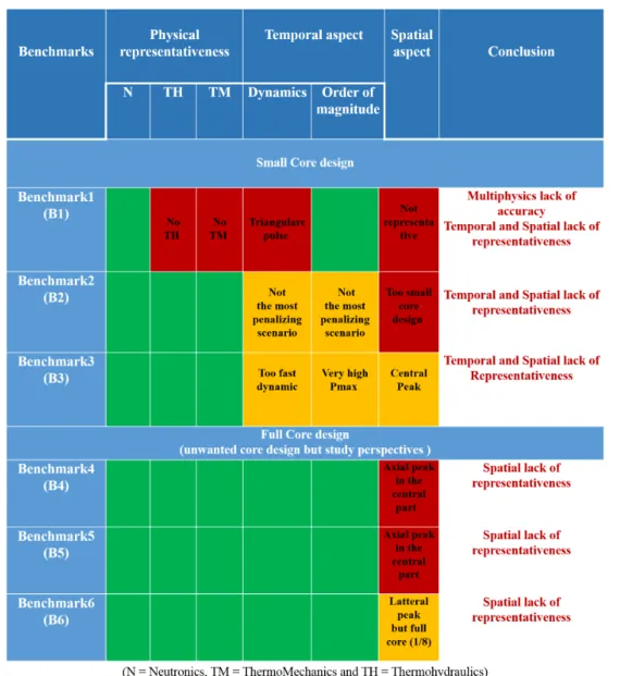
curve) Fluid Density (bottom cureve) function of time [186] . . . 30 2.9 Benchmarks comparative table regarding the accuracy of each
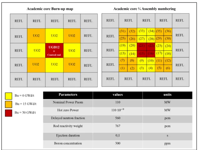
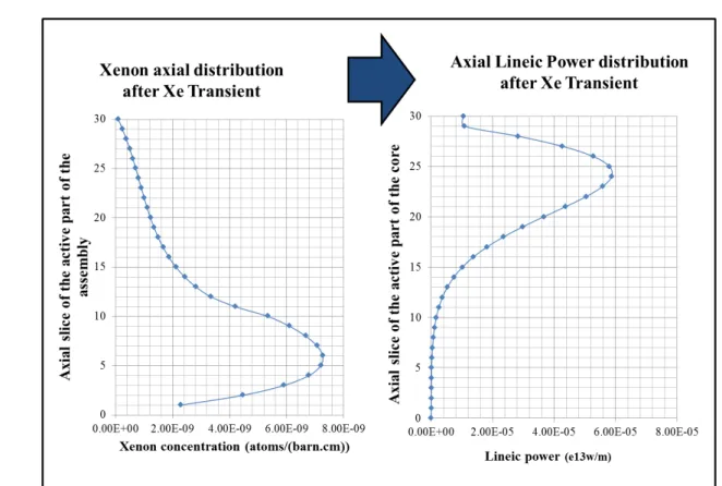
as-pect of representativeness, and presence of each physical discipline, we are looking for in this study (perfect accuracy, average accu-racy, rough accuracy) . . . 32 2.10 PWR small core (5x5) scheme . . . 34 2.11 Mini Core burn-up, assembly numbering and parameters description 36 2.12 Xenon and Power axial distribution after Xe Transient in 1/4
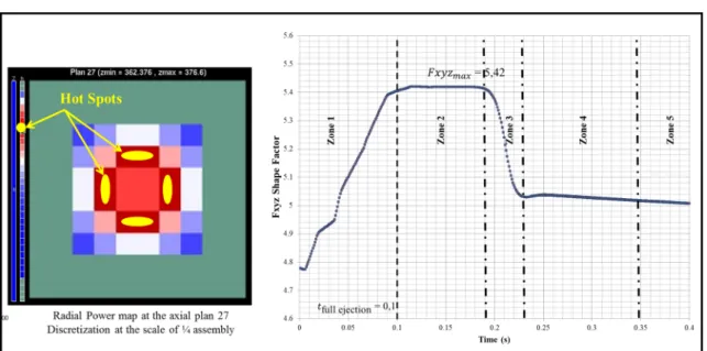
as-sembly (9) . . . 37 2.13 Power evolution during a REA transient . . . 38 2.14 APOLLO3 SA Hot spot locations and Max value of Fxyz shape
Factor evolution during the transient . . . 39 3.1 Precursor desintegration . . . 51
3.4 Space discretization (from the left to the right): A - Assembly composed by 2x2 homogeneous elements, B - Assembly composed by 17x17 homogeneous elements and C - Assembly composed by 17x17 unstructured and heterogeneous elements . . . 60 3.5 Multiparametred library calculation principle [188] . . . 65 4.1 Tab of the dynamics of the practical application of the Pin Power
reconstruction modeling . . . 75 4.2 Summary of our Minos-Minaret coupling approach . . . 76 4.3 Cell heterogeneity: Fuel Pin / moderator distinction . . . 77 4.4 Assembly heterogeneity: Fuel Pin cell / guide tube cell distinction 78 4.5 Coarse and a fine distribution of the thermal flux . . . 79 4.6 MINOS-MINARET Kinetic calculation methodology . . . 80 4.7 Academic core case full Minaret calculation with a discretization
at the scale of 4 cells/assembly, and with a refinement of a single lateral assembly at the scale of an unstructured fuel cell by mesh. 81 4.8 PPR and Minaret whole core calculations and comparison . . . . 82 4.9 PWR academic core (5x5) scheme . . . 83 4.10 MINOS SPn homogeneous core power maps calculation . . . 84 4.11 MINARET Sn Single Assembly pin power maps calculation . . . 85 4.12 MINARET Sn Single Assembly Accurate Power distribution . . . 85 4.13 Illustation of the Kinetic Post processed map of power deposit
inside the fuel pin . . . 86 5.1 Neutronics Block diagram with exchange variables and discretization 97 6.1 1D modelling with ALCYONE [164] . . . 120 7.1 Space domain discretisation [116] . . . 123
calculation example of distribution at t=0.25) . . . 127 8.1 ThermoMechanics Block diagram with exchange variables and
dis-cretization . . . 135 9.1 Initial discontinuous conditions . . . 150 9.2 FV9 numerical method scheme . . . 151 10.1 ThermoHydraulics Block diagram with exchange variables and
dis-cretization . . . 157 11.1 F4 - ALCYONE time coupling scheme with exchanged variables . 164 11.2 Multiphysics coupling scheme: spatial discretization and
corre-spondency. . . 165 11.3 Radial Fuel Pin discretization and exchanged variables . . . 166 11.4 Coupling validation with Transient at constant Power . . . 167 11.5 Core averaged fuel pin temperature profile comparison between the
fuel thermic ALCYONE standalone and F4-ALCYONE coupling using the transient scenario detailed in section ( 2.4) and Annexe( 15)168 11.6 Observation of the thermohydraulical effet through the ALCYONE
SA / FLICA4-ACLYONE comparison . . . 169 11.7 Tw sensivity and comparison regarding FLICA4 SA calculations
with different input data of Hgap . . . 170 11.8 A, S and Tw relative difference (FLICA-ALCYONE coupling) . . 171 12.1 Global coupling scheme and exchanged variables . . . 175 12.2 APOLLO3 - ALCYONE time coupling scheme with exchange
vari-ables . . . 176 12.3 Multiphysics coupling scheme: spatial discretization and
corre-spondency. . . 177 12.4 AP3 - FLICA4 time coupling scheme with exchange variables . . . 178 12.5 Multiphysics coupling scheme: spatial discretization and
corre-spondency. . . 179 12.6 Total time coupling scheme with exchange variables . . . 180
13.1 Coupling models description and comparisons . . . 183
13.2 Global and local variables/parameters regarding our three physical disciplines . . . 184
13.3 Integrated core power and energy comparison . . . 185
13.4 Hot Spot Power comparison . . . 187
13.5 Shape factor Fxyz and Fz variation comparisons . . . 188
13.6 Total reactivity variation comparison . . . 188
13.7 Doppler reactivity and Core Averaged Effective fuel temperature variation comparisons . . . 189
13.8 Moderator reactivity and Core Averaged Moderator Density vari-ation comparison . . . 189
13.9 Integrated Power time ranges definition . . . 190
13.10Integrated core Power comparison t12 . . . 191
13.11Total feedbacks reactivity variation comparison t12 . . . 191
13.12Doppler reactivity and Core Averaged fuel effective temperature variation comparison t12 . . . 192
13.13Moderator reactivity and Core Averaged moderator density varia-tion comparison t12 . . . 193
13.14Global Core Averaged - Local Host Spot Effective temperature and Moderator density variation comparison t12 . . . 194
13.15Core Averaged Fuel pin surface Twall comparison t12 . . . 195
13.16Hot Spot Fuel pin temperature distribution comparison . . . 196
13.17Hgap Global/Local Hot Spot comparison . . . 197
13.18percentage of each Hgap value regarding the core Hgap distribution at t3= 0.2s . . . 198
son around tmax_power . . . 200
13.21Integrated Power comparison t23 . . . 202
13.22Total feedbacks reactivity comparison t23 . . . 202
13.23Doppler reactivity and Core averaged Effective temperature com-parison t23 . . . 203
13.24Moderator reactivity and moderator density comparison t23 . . . . 203
13.25Global core averaged / Local Hot Spot effective temperature and moderator density comparison t23 . . . 204
13.26Integrated Power comparison t34 . . . 205
13.27Total feedbacks reactivity comparison t34 . . . 205
13.28Doppler reactivity and effective temperature comparison t34 . . . 206
13.29Moderator reactivity and Moderator density comparison t3−4 . . . 206
13.30Global core averaged / Local Hot Spot effective temperature and moderator density comparison t3−4 . . . 207
13.31AP3-FLICA4-ALCYONE (Rowland) and AP3-FLICA4-ALCYONE (C and SM) power pulse comparison . . . 210 13.32AP3-FLICA4-ALCYONE (Rowland) and AP3-FLICA4-ALCYONE
(Isotopic) power pulse comparison . . . 211 13.33Best Effort Coupling perspectives diagram regarding our PhD proof
of concept coupling . . . 216 13.34Best Effort disciplines models perspectives diagram regarding our
PhD proof of concept coupling . . . 217 14.1 Perspectives et améliorations du couplage Best Effort preuve de
concept pour atteindre le couplage Best Effort optimum . . . 225 15.1 PWR 1300 MW core map . . . 229 15.2 PWR 1300 MW core map and assembly location . . . 229 15.3 Assembly within a PWR 1300MWe . . . 230 15.4 PWR small core (5x5) scheme . . . 231
20.2 Total reactivity evolution couplings comparison . . . 254 20.3 Doppler reactivity and core average Effective temperature
evolu-tion couplings comparison . . . 255 20.4 Moderator reactivity and core average Moderator Density
evolu-tion couplings comparison . . . 255 20.5 Core average fuel pellet center temperature evolution couplings
comparison . . . 256 20.6 Core average fuel pellet surface temperature evolution couplings
comparison . . . 256 20.7 Core average clad surface temperature evolution couplings
com-parison . . . 257 20.8 Core average clad surface thermal flux evolution couplings
com-parison . . . 257 20.9 Core average Hgap evolution couplings comparison . . . 258 20.10Local Hot Spot Power evolution couplings comparison . . . 259 20.11Fxyz and Fz shape factor evolution couplings comparison . . . 260 20.12Local Hot Spot fuel pellet and cladding evolution couplings
com-parison . . . 261 20.13Global averaged/Local Hot Spot Effective temperature and
Mod-erator density evolution couplings comparison . . . 262 20.14Local Hot Spot clad surface temperature evolution couplings
com-parison . . . 263 20.15Local Hot Spot clad surface heat flux evolution couplings comparison263 20.16Local Hot Spot Hgap evolution couplings comparison . . . 264 20.17AP3-FLICA4-ALCYONE (Rowland) and AP3-FLICA4-ALCYONE
(C and SM) power pulse comparison . . . 265 20.18AP3-FLICA4-ALCYONE (Rowland) and AP3-FLICA4-ALCYONE
List of Tables
Table Page
2.1 PWR 1300MW Neutronics parameters typical order of magnitude [142] . . . 23 2.2 Thermohydrolical core inlet parameters . . . 29 2.3 PWR 1300MW and Academic core Neutronics parameters typical
order of magnitude [142] . . . 39 3.1 Neutronics notations: Neutronic quantities 1/3 . . . 46 3.2 Neutronics notations: Neutronic quantities 2/3 . . . 47 3.3 Neutronics notations: Neutronic quantities 3/3 . . . 48 3.4 Uranium 235 precursor (tabulated in JEFF-2) . . . 52 3.5 Main notation coming out the Neutronic problem formulation . . 59 5.1 Neutronics input, output and monitored parameters . . . 96 6.1 Notations: ThermoMechanical quantities . . . 102 6.2 Notations: Gaseous quantities . . . 103 6.3 Notations: Neutronics quantities . . . 103 6.4 Notations: Thermal quantities . . . 104 8.1 ThemoMechanics input, output and monitored parameters (where
r is the space variable at core scale and x is the local space variables)134 9.1 Notations: ThermoHydraulics quantities . . . 138 9.2 Notations: Phases and mixture quantities . . . 139 9.3 Notations: other quantities . . . 140 10.1 ThemoHydraulics input, output and monitored parameters (where
r is the space variables at core scale and x is the local space variables)156 13.1 Difference between AP3-FLICA4 and AP3-ALCYONE-FLICA4
calculation . . . 208 13.2 Difference between AP3-ALCYONE and AP3-ALCYONE-FLICA4
calculation . . . 209 13.3 Maximal relative difference between AP3-ALC-F4 (TRowland
ef f ) and
15.1 Core and Assembly description . . . 232 15.2 Core and Assembly description (academic core) . . . 232 15.3 Power and flux properties . . . 233 15.4 Power and flux properties (academic core) . . . 233 15.5 Hydraulical proprerties . . . 234 15.6 Hydraulical properties(academic core) . . . 234 15.7 Fuel pin description . . . 235 15.8 Thermal fuel pin properties . . . 235 15.9 Control rods properties . . . 236 15.10Moderator and poisons properties and composition . . . 236 15.11Reflector properties . . . 237 17.1 Features of the main rod ejection accidents [250] . . . 246
Part I
reactor was activated in 1942 and it decidedly paved the way for the development of con-tinuous research and production of many kind of Nuclear reactors.
Nevertheless, from the late 1970s until around 2002 the nuclear power industry suffered a certain decline in terms of trust which led to a decrease of construction rate. This fact has been amplified by the nuclear accident that occured at Fukushima in 2011 and, as a consequence, the decision taken by Germany to shut down its nuclear energy production in order to focus its production on renewable energy like sun or wind power.
However, the awareness of the importance of security of supply, the world-wide increase of the electricity demand, specifically in emerging countries, and, finally, the need to limit carbon dioxide emissions have contributed to the revival of the nuclear energy option within the Energy global plan. This global plan has been acted during the COP21 in Paris.
Thus, currently, the nuclear power is one of the fundamental components of the global energy mix and in order for the international nuclear production to integrate the low carbon energy mix with success, nuclear technologies would have to handle two fundamental points that have emerged from this conclusion:
• The nuclear power plants need to be more adjustable in terms of energy production in order to be able to quickly respond to the fluctuation of the renewable energy production as well as to the fluctuation of the electricity demand,
• The nuclear power plants need to be significantly safer in terms of design and in terms of monitoring.
The main goal of these measures is to ensure that the safety goals (core sub-criticality, core cooling, confinement of radioactive material, radiation protection) are fulfilled under any circumstances during normal operations (with intermittente Energy injected into the grid), off-normal states and accidents. These measures can be grouped in Prevention, Monitoring, and Mitigation.
The safety analysis of nuclear power plants requires a deep understanding of underlying keyphysical phenomena that determine the integrity of the physical barriers preventing fission product release, e.g. fuel pellet, fuel rod cladding, pressure piping system, reactor pressure vessel, containments, etc. At the present time, cutting edge models and codes produced by scientists exist but they mainly focus on a single aspect (discipline) of the physical system coupled with rough models of the other aspects needed to simulate the system. But, safety analyses can be carried out based on Multiphysical and Multiscales modelling in order to be the more accurate as we can regard all the physical aspects of the reactor behavior. This Best Effort approach (see chapter ( 16)in Annexe part) would give a full and accurate (High Fidelity) comprehension of nuclear safety and of operating conditions.
In this approach, the physical phenomena are simulated as accurately as possible (accord-ing to present knowledge) by coupled models (industrial codes) that were used separetely
the fuel pin or over the whole device stucture. A Best Effort approach would couple these models in order to realize a global and accurate modelling of the Nuclear reactor system. The Best Effort approach requires to define well the models that are used in order to ex-actly specify their limits, and hence, specify incertainties of the coupled model results in order to assume and optimize them.
Various research centers and research groups all over the world are enlisted in this new approach of system modeling, such as NURSIP [194] (and then NURESAFE [4]), CASL [1], MEANS [5] [263] [73], STARS [6]. The "Commissariat à l’Energie Atomique et aux Energies Alternatives" (CEA) is one of them. Nowadays, many coupled models are investigating over different systems (GEN II, III or IV) and over different aspects of these systems.
Taking, for example ,the Neutronics discipline of the nuclear reactor improvement of the models and simulation leads to the establishment of 3D neutron transport modellings of the reactor core.
A first step of the multiphysic coupling has been to couple Neutronics with Thermohy-draulics (the Best Estimate standard nuclear multiphysic coupling) and thus be able to study the two first safety principles, i.e., the control of the reactivity and the control of the cooling system. These coupling works have been done in many research centers or coop-erative works, e.g., for instance, at the CEA itself [222] [44] [247] through NURESAFE [45], in Spain at the Polytechnical Univ. of Madrid [120] at the Politechnical Univ. of Catalunya [201] [202], in Germany at the Technische Universitat Munchen [259], at the Karlsruhe Institute of Technology [260] [261] [115] , or in US at Penn State Univ. [114] [14] [70], Texas A and M Univ. [154], at the Michigan Univ. [269], at the Los ALAMOS lab. [175], mainly through CASL, MEANS and STARS projects. Next, regarding the potential threat to the fuel pin in case of standard and accidental situations of the GEN II-III Reactors, the primary contribution would be the incorporation of a fine thermome-chanical model into a coupling including Neutronics and Thermohydraulics (Standard Best Estimate coupling). This way, a specific futher step has been done in order to meet this ambitious goal. Many research centers in the US at the Lawrence Livemore National Lab. [73] , at the Noth Carolina State Univ. [264], at the INL [63] [94] [154] and at the Pall Scherrer Institut [77], in Europe through NURSAFE [45] or moreover at the CEA [249] [145] [66], are working on this purpose and are source of proposals considering the coupling approach and technics, i.e., from external linkage [191] to strong external [70] [249] or internal coupling [66] and preparation work of JFNK internal coupling [66].
It is in this context that this PhD Proof of Concept thesis work is being under taken. It consists in the "Development of a Multi-physics and multi-scale Best Effort modelling for accurate analysis of Pressurized Water Reactor under standard and accidental operating situtations". It mainly involves the implementation of a multiphysics algrithms coupling
elementary scale of the assembly. In addition, a work project has been carried out in order to prepare or improve the structures to access the local physical information that would lead to the implementation of a future multiscale coupling scheme, at the elementary scale of the fuel in, i.e., the fuel cell (fuel pin surrounded by the moderator) or sub canal (cool-lang with fuel pin in the corners).
As it was planned, this Neutronic, Thermohydraulics and Thermomechanics multi-physics coupling yields:
• In terms of Neutronics, a better awareness of the Power evolution through precise feedback effects (Doppler, moderator), thanks to a more accurate thermal description of the Thermomechanics and Thermohydraulics aspects of the core.
• In terms of Thermohydraulics, a better awareness of the thermal exchange between the fluid and the fuel pin from the very beginning of the thermal activation.
• In terms of Thermomechanics, a better awareness of the thermomechanical evolution and thermal release through the cladding surface to the fluid, including a strong contribution at the interface between cladding and pellet (Hgap).
The road map of this paper is described below.
The first part of the present paper aims to carry out the physical context and scientifc objectives of the study. After a short presentation of the multiphysical and multiscale context of this industrial complex system, we define the academic case and describe the physical scenario of the study aiming to achieve a complete and detailed comprehension of the major physical phenomenology of the scenario. Thanks to this description and expla-nation, we present the scientific objectives of this study according to the safety analysis and Best Effort coupling of Industrial CEA codes.
The second part is dedicated to the mathematical and numerical Neutronic models which we detail. We define their numerical formulation in order to pin point the coupling vari-ables of our multiphysics problem as well as to define the limitations of the models and the assumptions and hypothesis we made. Finally, we present the improvement of the models we realized in order to reach our multiphysics multiscale goals.
The third part is dedicated to the description of the mathematical and numerical Ther-moMechanical of the fuel pin models as well as of the Thermohydraulical models. As in the Neutronics part, we detail the mathematical models and the physical phenomena they carry out and we define briefly the numerical formulation. This allows us to pin point the ThermoMechanics and Thermohydraulics coupling variables of our multiphysics problem as well as to define the limitations of the models and the assumptions and hypothesis we made. Finally we expose the thermal approach which have been developed for the fuel pin - fluid coupling of the thermal exchange and define the fuel pin effective temperature formulations we implemented.
Thermohydraulics coupling and effects of the coupling on the simulation. Thereafter, we gradualy increasing the multiphysics coupling, i.e., from the Hydraulics and Thermome-chanics simplification up to the total Neutronics - Thermohydraulics - ThermomeThermome-chanics coupling. These sections present the methodology, the results we obtain and some circum-spect physical analysis with recircum-spects to the limits on the physical representativity of our academic core and scenario.
The conclusions and perspectives of our work are presented in the final part of this docu-ment.
Part II
Physical context and scientific
objectives
The Nuclear Reactor: a multi
physical system
In this chapter, we will introduce the physical context of the study through the definition of a nuclear reactor in terms of multiphysics and complexity. Indeed, it is necessary to well define the nuclear reactor, which is a complex system with many scales of analysis and involving many fields within the physics.
1.1
A multiphysical complex System
A nuclear reactor is used at nuclear power plants for electricity generation. Heat pro-duced from nuclear fission is passed to a working fluid (primary circuit - the heated part) which runs through steam turbines that run electrical generators in order to produce elec-tricity (secondary circuit - the electrical part). Then the remaining heat is released to the atmosphere thanks to the cooling tower (tertiary circuit).
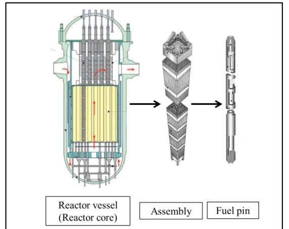
Between these three parts of the nuclear power plant, our interest lies within the heated part which is composed of the reactor vessel (the pressure vessel containing the nuclear reactor coolant that carries the fission heat to the thermal exchanger), the reactor core shroud (the stainless steel cylinder surrounding the reactor core and which main function is to direct the cooling water flow) and the reactor core (the portion of the nuclear reactor containing the nuclear fuel components immerged in the fluid coolant and where heat gen-eration takes place). For the purpose of this work, we will only focus on the reactor core part. This is the heart of the nuclear reaction chains that produce heat by fission inside the fuel pellet to be released to the fluid coolant.
re-Figure 1.1. Nuclear Power Plant description
actor core: Neutronics, that defines the neutron transport, distribution and time evolution; the Fuel Performance, that defines the behavior of the fuel pin in terms of thermics and me-chanical phenomenum; and Thermohydraulics, that defines the thermal exchanges of heat with the fluid coolant and its transport according to the evolution of the charateristics of the fluid. In a few words, these three physical fields can be defined as follows:
• Neutronics: it is the study of the motion and iteraction of neutrons with materials. Free neutrons collide with the atoms of the fuel material. The shock causes the fission of the nuclei of certain atoms such as Uranium 235 (U5), that splits into two ligther nuclei (fission products), releasing kinetic energy, gamma radiation and free neutrons which can then interact with other fissible nucleus, etc. A portion of these neutrons may also be absorbed by fertile or unfertile atomic nuclei, or simply leave the core and disappear from the total neutron account. The overall behavior of the chain reaction is related to the effective multiplication factor keff. Indeed, it determines its evolution according to the neutrons production (Prod.) and consumption (Cons.): N fissions create Nkeff fissions, themselves producing (Nkeff)2fissions. Several evolution
cases exist, depending on the value of Keff:
– keff < 1, the reaction is subcritical and tends to shut down the reactor (Cons.
> Prod.).
– keff > 1, the reaction is supercritical and there is a risk that the reactor
– a steady reaction is defined by keff = 1 : in this case the reaction is maintained
at a constant level (Cons. = Prod.).
Hence, Neutronics models are fundamental to understand and to determine the trans-port and distribution of the neutrons inside the core in order to estimate and control the nuclear reaction.
• Fuel performance: in Gen-II light water reactor, the fuel pin is a ceramic pellet mate-rial initially composed of Uranium Oxyde (UO2) circled by a Zirconium metal clad. The pellet is the location of the fissile atomic nucleus such as Uranium-235 which could absorb neutrons, decay by fission and release heat into the pellet. Moreover, the fuel pin will undergo mechanical and thermal reactions such as thermal expansion of the pellet [141] [125] [147] [227] [83] [199]. The neutrons are interacting at the scale of the nucleus, thus the slightest change of the fissil nuclei repartition inside the pellet by thermal expansion may lead to a very different neutrons distribution, to a very different nuclei fissions distribution and thus to changes in heat production and release. Other aspects of the fuel pellet, such as containement of radioactive mate-rials inside the clad, could also be discussed from the fuel performance and safety analysis point of view [112] [111] [33] [13] [49].
• Thermohydraulics: in addition to fluid transport, the fluid coolant is also used to thermalize the neutrons (they scatter on hydrogen nuclei of water and they reach a lower energy suitable for the neutron to be absorbed by fissile nuclei) and to moderate the nuclear reaction by adding neutron poisons into the water (they absorb neutrons without fission in order to limit the neutron amount inside the core). Consequently, in addition to the coolant property of the fluid, the thermal characteristics of the fluid as well as of the fuel pin are essential data to feed the neutronic studies and control the heat production/coolability of the core.
Figure 1.2. Pressurized Water Reactor vessel, reactor assembly and fuel rod
1.2
The multiscale system
The reactor core can also be described following different scales of analysis. Many parameters could be studied following several scales of description, figure ( 1.3) and in the chapter ( 15) in Annexe part, such as, for instance, the Power. The neutronic power is the energy function of time generated by the reactor core and which can be describe globally (integrated power Pintegrated(t)), localy (local power P(x,t) or regarding the medium of production or deposition (fuel pin, coolant water and so on).
• the core scale itself can provide a global prediction. This way, we mainly highlight the variation of amplitude of parameters of interest. However, this approach assumes a close to constant distribution of the studied parameters and considers the core as a homogeneous system.
• the assembly scale gives use a more accurate description of the core. Assemblies are considered as homogeneous medium but thanks to this description we can distinguish between assemblies and obtain a spatial distribution of our studied parameters such as the core heterogeneity of the power distribution in case of incidental or accidental
situations .
• the fuel cell scale: from the homogeneous assembly scale, we can refine our description up to a 17x17 fuel cell grid that is the ultimate homogeneous refinement regarding the fuel pin. Indeed, an assembly is composed of a 17x17 grid of fuel pin surrounded by water. At the fuel cell, we consider a cell composed by a single fuel pin surrounded by water. This way, we have an accurate distribution of parameters inside the assembly (assembly heterogeneity) but we do not distingish between coolant and fuel pin, and have no insight on the fuel pin itself.
• the fuel pin scale: at this scale we distinguish the coolant from the fuel pin, and we obtain a precise distribution of parameters inside the assembly and inside the fuel pin with distinction between the clad and the pellet. Consequently, we are able to define precisely the whole behavior of the core as well as its very local evolution. This scale has obviously a very high computing cost of simulation but may lead to a thorough safety analysis.
Figure 1.3. PWR core Scale of modelling scheme
A full fuel pin scale discretization of the core would be the Best Effort to model the core but not the most efficient approach (chapter ( 16) in Annexe part). The most ef-ficient approach depends on the parameters we study according to the heterogeneity of their distributions and variations of their amplitude. Consequently, an homogeneous point
versely, a full fuel pin scale discretization would be necessary if the whole core distribution of the studied parameters is very heterogeneous with a huge variation of amplitude. A mix between an homogeneous scale and a fuel pin scale would be efficient if the studied parameters distribution is heterogeneous with a highly localized variation.
In conclusion, in order to define the scale of discretization for a Best Effort approach we need to take care of the different aspects quoted:
• Phenomenum comprehension,
• Amplitude and distribution of parameters,
• Computing cost according to the improvement of the accuracy of the calculation. These aspects will be taken into account and confronted to the the transient phe-nomenology part of this document, and in more details in the following papaers [141] [125] [147] [227] [83] [199], in order to scientifically defined and justify our academic case, our modelling and simulations.
1.3
Multiphysics coupling State-of-the-art
[112] [111] [33] [13] [49] [181]
As it was said in the previous section, during the last decade various research centers and research groups all over the world have been enlisted in this new approach of system mod-elling, such as NURESIM european project (NURESAFE [4] and NURISP multi-physics platform [194]) , CASL [1], NEAMS [5] [263] [73], STARS [6]. The "Commissariat à l’Energie Atomique et aux Energies Alternatives" (CEA) throuhg the CORPUS plateform is one of them. Our present work is a contribution to the Multiphysics CORPUS effort as the first Neutronics - Thermohydraulics - Thermomechanics CEA coupling.
Regarding Reactivity injection Accident and taking arbitrarily, the Neutronics discipline as the key stone of the Nuclear core simulation, the first step of nuclear modelling improve-ment was to evolve from kinetic point models to 3D neutron transport modellings.
Then, a first step on multiphysics coupling was to couple Neutronics with a fine fuel pin Thermics in order to accurately simulate the thermal behavior of the pin and thus the neutronic thermal feedback behavior (Doppler Feedback) [134] [239].
Then, a second step was to couple Neutronics with fuel pin thermics and Thermohydraulics in order to simulate the precise thermal behavior of the pin, of the fluid and thus of the whole neutronic thermal feedback behavior (Doppler and moderator Feedbacks) [222]. Today, the third step of multiphysics coupling consists in coupling Neutronics, Thermohy-draulics and a fine Thermomechanics in order to obtain thorough simulation results of the core reactor and more precisely, in case of REA, of the fuel pin and its cladding (the first containment barrier) [200].
NEA-OECD (benchmarking), two of the leading ones international projects, i.e., NURE-SAFE [4] and CASL [1] (research, benchmarking and multiphysics plateform developp-ment) and the CEA-EDF multiphysics plateforme SALOME [7] (used in stand alone but also used in NURESAFE for research, benchmarking and multiphysics plateform devel-oppment):
• NEA-OECD [178]is an intergovernmental agency that facilitates cooperation among countries with advanced nuclear technology infrastructures to seek excellence in, for instance, nuclear safety, technology, and science. One of the goals of the NEA in this area is to assist member countries in ensuring high standards of safety in the use of nuclear energy. For this purpose, NEA is working on the development of ad-vanced multiphysics modelling project which are leading to Benchmark identification and definition, such as EGUAM [185] [187](uncertainties and physics) and EGM-PEBV (validation and physics), in order to be proposed to international modelling community.
• CASL is an ambitious US project lead by Oak Ridge NL and where major US nuclear actors are involved: 3 National Laboratories (Idaho National Laboratory (INL), Los Alamos National Laboratory (LANL), and Sandia National Laboratories (SNL)), 4 Academic patners (the North Carolina State University (NCSU), the University of Michigan (UM), and the Massachusetts Institute of Technology (MIT), The Elec-tric Power Research Institute (EPRI). Industrial companies such as Westinghouse Electric Company (WEC) and operators such as The Tennessee Valley Authority (TVA) are also worth mentioning. It is the first DOE Energy Innovation Hub which focuses on a single topic, with the objective of rapidly bridging the gaps between basic research, engineering development and commercialization. The CASL’s VERA [238] multi-physics plateform is currently coupling physics such as neutron transport, thermohydraulics, fuel performance, and coolant chemistry. For instance, research and benchmark works have been carried out such as [114], [269], [175].
• NURESAFE [4]) is mainly a European project involving major European nuclear ac-tors, namely 4 major European nuclear industrial companies (AREVA, TRACTEBEL, EDF, FORTUM), 9 major European nuclear Research and Development Organisms (CEA, HZDR, KIT, PSI, VTT, KTH, KFKI, JSI, UJV, ENEA, NCBJ), 2 major European Technical Support Organisations (IRSN, GRS), 4 European Universities (LUT, KTH, UPisa, UCL) and two US Universities (PSU, TAMU). The NURESIME plateforme project pursues transient simulation studies using coupled System Ther-mohydraulics, CFD, subchannel Thermalhydraulics, Neutronics and fuel Thermome-chanics [238]. In this framework, some multiphysics coupling have been completed such as the ATHLET-DYN3D coupling, the ATHLET-CTF-DYN3D coupling or the SCANAIR-FLICA4 coupling which are respectively dedicated to System-Neutronics coupling, System Thermohydraulics Neutronics coupling and Thermohydraulics -Thermomechanics coupling [238]. For instance, research and benchmark works have been carried out such as [42] [222], [44], [259] .
and Post-Processing for numerical simulation. It is based on an open and flexible architecture made of reusable components. The SALOME [7] application named CORPUS [233] is dedicated to Best Effort multiphysics modeling of PWR in normal and accidental situations, mainly by using CEA codes. CORPUS research works have been carried out on coupling such as on Thermohydraulics, Neutronics-Thermomechanics or Core Thermohydraulics -System Thermohydraulics [44] [247], [249], [145], [191].
Transient scenario phenomenology of
a Rod Ejection Accident
The goal of this work is to realize a Best Effort modelling of the core in case of an acci-dental situation which violates some of the safety functions of the core and may endanger its safety barriers (chapter ( 17) in Annexe part and [147]).
For this purpose, we pinpoint a specific scenario involving our three disciplines, i.e., Neu-tronics, Thermohydraulics and Thermomechanics. This kind of scenario is one of the paramount concerns of the nuclear safety because of the treath on the first containement barrier, i.e., the fuel pin integrity, and requires an accurate Thermomechanics modelling. We focus our study on a Reactivity Injection Accident (RIA) initiated by a control rod ejection and called Rod Ejection Accident (REA).
In this chapter, we describe the Phenomenology and physical aspects of this transient ac-cident. More precisely, we will focus on the risk of mechanical damaging or failure of the clad, i.e., the first barrier ( [141] [125] [147]), following the neutronic pulse induced by the REA transient. In addition to a strong thermal coupling, there are two major neutronics effects we do need to define: feedback reactivity reactions which are stabilizing or desta-bilizing response of the matter to a disturbance in the neutron balance of the core; the heterogeneous distribution of the power which might lead to a spatial dissymetrical deposit of power on the fuel pin which itself might carry the fuel pin to dangerous conditions (fuel pin rupture or fuel melting).
2.1
REA classical transient overview
[142] [147] [250]
We assume that before the transient the power inside the core is constant and the neutron population balance is stable (Keff = 1). When the rod is ejected the balance is
broken ( [125] [147]).
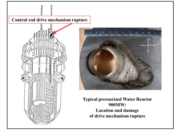
In a Rod ejection accident (REA), there is a mechanical failure of the housing of a control rod drive mechanism (figure 2.1) so that the internal pressure in the core (Pint = 155
bar) forces the mechanism out (Pext = 1 bar) and the attached control rod assembly is
ejected vertically from the reactor. This difference in pressure pulls the control rod out with an acceleration of about 22 g (22 x 9.81 m.s−2) and leading to a very short time of ejection (about 0.1 s). In addition, this accident may lead to a loss of primary coolant [69] through the failed control rod drive. This aspect is not considered here: we assume that the loss of primary coolant is negligible or nonexistant during the duration of the transient.
Figure 2.1. Image of a rupture of the control rod attachement (Badcock and
Wilcox work on 900MW PWR) [16]
The complete withdrawal of a control rod induces a high, quick and localized incursion of reactivity into the core. The map of power is strongly deformed nearby the assembly where the control rod has been ejected. The intensity of the REA transient depends on its reactivity insertion ρo (the insertion state of the rod and the composition of the
neutron-absorbing material) and the delayed neutron fraction β of the core (map of Burn-up and reloading map). Following these two parameters, we are able to distinguish two types of transients, i.e., the supercritical transient cases where the reactivity ρo is inferior to the
reactiv-ity ρo is superior to the delayed neutron fraction β. The last one is clearly more violent
than others due to the predominancy of prompt neutrons in the neutronic reaction. It is characterized by the production of a huge peak of power proportionally to the importance of the difference (ρo− β).
In case of a supercritical prompt transient, the celerity of reactivity insertion and neu-tronic feedbacks of the reaction separate the REA scenario in three distinct phases [141] [39].
The first phase of the accident corresponds to a local fast and strong power incursion due to the ejection of the control rod. During this phase of a few milliseconds, in case of low power initial value, the increase of power does not induce any significant increase of temperature inside the pellet or the coolant.
The second phase of the accident is due to the prompt neutron action and is charac-terised by a strong mechanical interaction beetwen the pellet and its clad as a consequence of the quasi-adiabatic warming and the high pressure of the fission gas which lead to the sharp increase of the volume of the oxide. In case of brittle failure of the clad, during this phase, the release and spread of small pieces of fuel to the primary coolant may induce a drastic vaporisation of the water around the fuel pin and potentially a vapor explosion, which in turn might damage the neighbouring fuel pins.
The reaction shuts down by itself as a result of the fuel warming and this is called the Doppler feedback effect. Indeed, the Doppler feedback effect comes out as a dependence of the neutronic absorption to the fuel temperature. More precisely, it means the increase of steril absorption according to the increase of the fuel temperature.
The third phase of the accident is controlled by the thermal evolution of the system and it extends over few seconds in time up to the end of the transient (according to the kinetic and intensity of the transient). This phase leads to a sharp increase of the clad temperature and a high inner pressure in the fuel pin that may induce a boiling crisis of the water around the fuel pin and the ductile failure of the clad. In this phase, in addi-tion to the Doppler, the major feedback effect is the moderator effect which consists in the modification of the neutronic slowing down. Indeed, the moderator density decreases and induces the sharpening of the neutron spectrum. Hence, less fission occur and it is equivalent to a negative insertion of reactivity into the core.
At last, in a classical reactor, if the detected flux (that has been measured during the two previous steps [69]) exceeds a given setpoint, an automatic reactor trip (AAR) will be initiated causing insertion of the remaining control rods into the core in order to damp the neutron flux. This aspect will not be taken into account in our study.
This scenario can be described by splitting the physics into two parts. On the one hand, the Neutronics part is defined bu its initial state (Bun-up, Xe inventory, Power P0, and so
on) and its transient behavior (integrated and local power, shape factor, reactivity and cross section variation): both are needed to determine the most penalazing scenario in terms of power production. On the other hand, the ThermoMechanics and the Thermohydraulics, at their initial state (mainly, the Mechanical state of the fuel pellet and clad) will strongly impact the transient evolution in terms of Thermics (fuel temperature Tpin and Twall, thermal flux Φwall and so on) but also in terms of Mechanics (Gap size) and Hydraulics
(moderator density, RFTC). Then, as detailed in [147] the REA transient may lead to different risks of failure (fragile or ductile). These risks will not be treated during this study but they are detailed in [147]. They underline the importance and requirement of a well and precise understanding and monitoring of the physics during the transient.
2.2
Physical specifications
The goal of this work is to realize a multiphysics modelling by coupling accurate Neu-tronics, Thermohydraulics and Thermomechanics physical models. For this purpose and in order to simplify the realization of the coupling scheme as well as the results analysis we decide to realize our study on a small core reactor model. These two points imply the need of an accurate representativeness of our case regarding a classical PWR (design specificities and symmetry) and considering a typical transient accident governed by prompt neutron (supercritical prompt transient). More precisely, our core and transient case need to be representative in terms of phenomenology and need to be the most constraining scenario considering the risk of endangering the first safety barrier (safety analysis context even
if this aspect will not be covered by this study).
2.2.1
Neutronics representativeness
The REA transient is first and foremost a Neutronics transient. The paramount concern of the neutronics representativeness of this scenario is the power evolution and distribution during the transient. We must consider the two following aspects:
• Temporal aspect: typical temporal dynamics (typical shape of the curves and order of magnitude) we can observe considering the core power Pneutro(t) and the 3D shape factor Fxyz(t).
• Spatial aspect: typical spatial distribution we can highlight through the Hot Spot localization.
Temporal aspect
[142]
In a typical situation, we will have a transient as described in Fig ( 2.2), which was obtained using a neutronics REA simulation at the CEA [142].
• Core Power P neutroIntegrated (t) :
The Power evolution in the core can be described following five steps [39].
During a REA, we can describe the power transient dynamic following 5 typical zones as, for instance, in the figure ( 2.2):
– Zone 1: Rod ejection at hot zero power.
– Zone 2: Dramatic increase of the Power (exponential evolution) without any
significant increase of the temperature due to the low power intial value (no reactivity feedbacks).
– Zone 3: Quasi-adiabatic heat, the energy is confined inside the pellet. The Pcore
increases very violently and very locally. During the same time, the Doppler feedback effect (Doppler reactivity ρdoppler) quickly increases and compensates
the reactivity from the rod ejection ρrod. At this time, the reactivity does not
increase any more (max of the power increase) and finally decreases as fast as it grows.
– Zone 4: The thermal transfer in the fuel pin leads to the heating of the moderator
and induces a moderator feedback effect (moderator reactivity ρmoderator).
– Zone 5: The reactivity of the core reaches the delayed neutron fraction and
brings the core to a new equilibrium state. In fact, an operating reactor does not have the time to reach this state because of the emergency shutdown devices that damp the neutron flux. In our case, we won’t use any emergency shutdown devices.
Figure 2.2. Power ratio evolution (P(t)/Pnom) during the transient (case REP1300-UOX) [142]
This dynamic is also observed locally through the power distribution P(x,t) and more specifically in the Hot spot area. In addition to this dynamic, the width of the peak, associated to the power amplitude of the scenario, are fundamental in order to de-fine our transient. Pmax is function of the core initial state, i.e., the control rod reactivity and of the delayed neutron fraction. These features of the scenario carry the amount of power deposition inside the core and directly influence its behavior in terms of safety. The specific energy deposition in the fuel during the pulse is given by the integral of the power over the duration of the transient. Consequently, a high amplitude of the power pulse would be dangerous, but the width of the pulse (total energy deposition) would also bring a very significant component of threat for the fuel pin.
• Shape Factor Fxyz(t) : The 3D shape factor Fxyz corresponds to the value of the max deformation of the power distribution compared to the average value of the power inside the core [142].
Fxyz =
maxx,y,z|Ppin(x, y, z)|
< P (x, y, z) > (2.1)
More precisely, it informs on the amplitude and the variation of the power due to neutronic impacts of the transient (control rod reactivity insertion ρrod and doppler
ρDoppler or moderator ρmoderator feedback reactions) [39].
For instance, the following figure ( 2.3) shows a typical REA transient and Fxyz shape factor variation during the transient [142]. We can observe the same 5 typical Zones we observed in the previous section regarding the Power:
Both are dependent of the rod reactivity weight and core state, i.e., delayed neutron fraction and thus of the Burn-up distribution. Indeed, the Burn-up map distribution of the core evolves during the reactor operation [195]. This way, the concentration of isotopes and fission products proportionnally changes from the start, i.e., Begin Of Life (BOL) or Begin Of Cycle (BOC), to the end of a fuel cycle process of the reactor operation, i.e., End Of Cycle (EOC). More precisely, the management of the reactor operation (historical effect and number of cycles) and the fuel assembly repartition at the start induce a spe-cific distribution of the isotopes and their concentration. The isotope concentration inside the core is one of the factors that may lead the transient to the most penalizing scenario. Indeed, the fuel consumption during the fuel cycle reactor operation induces a significative reduction of the delayed neutron fraction. For instance, in a general case, we assume values from 700 pcm at BOC to 500 pcm at EOC and, and in a pessimistic case due to the reactor historical effect, we assume values from 520 pcm at BOC to 440 pcm at EOC [142]. The lesser is the number of delayed neutrons, the more the transient will be prompt critical (governed by prompt neutrons) and thus it will be fast and strong.
Figure 2.3. Shape factor evolution Fxyz(t) during the transient (case REP1300-UOX) [142]
Neutronics parameter value
Delayed neutron fraction 450 pcm
Control rod reactivity weight 700 pcm ' 1.5 $
Burn-up heterogeneity from 10 to 45 GWd/t
Rod Ejection duration 100 ms
REA duration to asymptotic power 600 ms
Width of the power pulse 40 ms
Max integrated power 10 Pnom
Max value of the 3D shape factor Fxyz 20
Max local power 200Pnom
Table 2.1. PWR 1300MW Neutronics parameters typical order of magnitude
[142]
Then, the tab ( 2.1) gives the standard 1300MWe PWR Neutronic Parameters regarding the stage of the fuel cycle [39].
Figure 2.4. Burn-up heterogeneous distribution given in GWd/t (case REP1300-UOX) [142]
Spatial aspect
[142]
The considerations are also taken from: • Hot spot radial localization:
PWR reactor core is made of different types of assembly in terms of isotope inventory and number of fuel cycles (Burn up). These aspects strongly impact the neutronic reactivity (as described in the previous section) but also the local behavior of each assembly. In addition, the control rods are dispached symmetrically (1/8 symmetry) in the core from the center to the peripheral zone of the core (chapter ( 15)in Annexe part). This disposition is explained by the fact that the core area impacted by each control rod is approximatively restricted to a square of 9 assemblies including the control rod assembly. The ejection may concern any of the control rods of the core but, considering the impact area of each control rod, the more the location of the ejected control rod is peripheral and close to the reflector, the more heterogeneous the power distribution is during the transient [141]. Moreover, It has been observed that the hot spot location generally does not appear in the assembly where the control rod had been ejected but within its nearest lateral neighbor [141].
Figure 2.5. 2D Power distribution at the moment the control rod ejection is
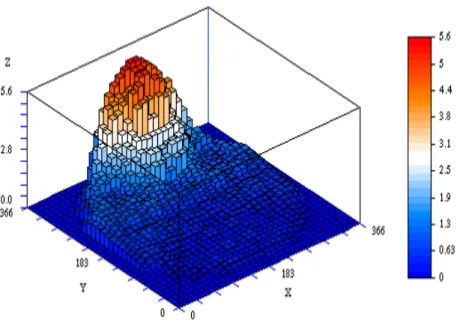
completed (case REP1300-UOX) [142] • Hot spot axial localization:
During the steady situation at Pnom (standard operation of the reactor), the axial
flux shape has a quasi symetrical and centered distribution, in case control rods are extracted, and, in case control rods are inserted, it has a peak in the lower part of the core. After we shutdown the reactor, we observe the increase of the Xe concentration up to its maximum value, approximately at 6.7h) and then the asymptotical decrease of the Xe concentration [141] [125].
According to the safety analysis and regarding the most restritive scenario, the rod ejection accident should happen when that the Xenon concentration has reached its maximum value. An order of magnitude of the core poisoning of a REP is given by [214]: at steady state we have about 3000 pcm for the Xe135. As a consequence of the
shutdown of the reactor, the concentration of the Xe and Sa increase to a maximal peak of about 5000 pcm for the Xe135 [214].
Consequently, due to the peaked distribution of the flux in the lower part of the core (according to the control rod insertion) the increase of Xe has a axial distribution also peaked in the lower part of the core. Thus, if for instance the reactor is accidentaly restarted during this Xe transient, the axial distribution of the Xe will lead to pull up the flux distribution to the top of the core when we extract the control rods.
![Figure 2.3. Shape factor evolution Fxyz(t) during the transient (case REP1300-UOX) [142]](https://thumb-eu.123doks.com/thumbv2/123doknet/2926418.76973/48.892.242.664.186.510/figure-shape-factor-evolution-fxyz-transient-case-rep.webp)
![Figure 2.4. Burn-up heterogeneous distribution given in GWd/t (case REP1300-UOX) [142]](https://thumb-eu.123doks.com/thumbv2/123doknet/2926418.76973/49.892.280.631.168.505/figure-burn-heterogeneous-distribution-given-gwd-case-rep.webp)