OATAO is an open access repository that collects the work of Toulouse
researchers and makes it freely available over the web where possible
Any correspondence concerning this service should be sent
to the repository administrator:
tech-oatao@listes-diff.inp-toulouse.fr
This is an author’s version published in:
http://oatao.univ-toulouse.fr/26981
To cite this version:
Salem, Mohamed Medhat
and De Luycker, Emmanuel
and Delbé, Karl
and Fazzini, Marina
and Ouagne, Pierre
Experimental investigation of
vegetal and synthetic fabrics cohesion in order to prevent the tow sliding defect
via frictional and pull-out test. (2020) Composites Part A: Applied Science and
Manufacturing. ISSN 1359-835X
Experimental investigation of vegetal and synthetic fabrics cohesion in order
to prevent the tow sliding defect via frictional and pull-out test
M.M. Salem, E. De Luycker
⁎, K. Delbe, M. Fazzini, P. Ouagne
Laboratoire Génie de Production (LGP), Université de Toulouse, INP-ENIT, Tarbes, France
Keywords: Fabrics/textiles (A) Defect (B) Mechanical properties (B) Mechanical testing (D) A B S T R A C T
The tow-sliding defect also referred to as gapping that appears during complex shaping of woven reinforcements is due to a loss of cohesion in the fabric. The cohesion of the fabric tends to keep the tows from sliding under tension. This cohesion depends on the frictional behavior of the tows mainly. Other factors such as the weave of the fabric, the tensions and shear state of the fabric during forming play an important role as well. An analysis of the frictional behaviors of the tows coupled to out of plane pull-out tests to determine the influence the aforementioned parameters on the cohesion of the reinforcements was then carried out. It was showed that the cohesion of the fabric, limiting the risk of appearance of tow sliding defect, can be improved by increasing the transverse tow tension in low shear region, and by the in-plane shear itself in highly sheared zones.
1. Introduction
The resin transfer molding (RTM) is a manufacturing process, which consists of preforming a fabric between two parts of a mold and in-jecting pressurized resin through the preformed reinforcement. Since its early versions in the 1970s, RTM became a widely used process to manufacture lightweight, complex, mechanically adapted, structural components for innovative industries such as in the aeronautic and automotive areas[1–4]. Despite its interest, the process is still prone to defects. The defects lower the mechanical properties of the finished product [5]. Some defects are due to the resin injection part of the process. Others are due to the preforming part. Some of these defects have been the subjects of different experimental and numerical in-vestigations, e.g. fabric wrinkling [6–11], unidirectional prepreg wrinkling [6,11–13], fabric waviness [14,15], prepreg waviness
[13,14,16–18], tow buckling[19–25], prepreg buckling[26,27]. Defect such as the tow sliding (also referred to as fabric unweaving, gapping or reinforcement de-cohesion) has also been investigated in the past but it still needs to be fully understood and characterized.
Tow sliding was observed by Ouagne et al.[22]on plain weaves during preforming on a highly curved tetrahedral punch. It was re-ported that the pressure applied by the blank holders on the fabric was a key factor in the apparition of the tow-sliding defect. Allaoui et al.
[28]observed similar results with interlock multilayer reinforcement on a prismatic punch. It was observed that the appearance of defects during multilayer forming occurred mostly when the relative sliding
between layers was larger than the length of a fabric unit cell. In that case, the higher the fabric-to-fabric friction is, the prompter the ap-pearance of defects takes place. Nezami et al.[29]explored several parameters on the preforming of woven reinforcements. The fabric-to-tool and fabric-to-fabric dynamic frictions were tested using a sliding test bench. Fabric cohesion was tested during in-plane shear using a dedicated picture frame test by pulling out one tow from the center of the fabric. The influence of the blank holder pressure on the defects appearance was investigated using a segmented blank holder with differential pressure. Labanieh et al.[30]stated that the tow sliding defect is the consequence of a loss of cohesion between tows due to an increase in the tows tensions. They demonstrated experimentally and analytically the influence of the tows tensions and fabric-to-tool friction coefficient on the appearance of the defect. Gatouillat et al.[31]used a mesoscale model to simulate the shape forming process and predict the in-plane shear and sliding defects that may occur. Shell elements were used to represent the tows as they allow introducing a bending rigidity and induce a normal inter-tows load, which in turn allowed for a more accurate frictional behavior of the fabric. Iwata et al.[23]used a hybrid meso-macro scale model to simulate the forming process. The macro-scale part was used to simulate the boundary conditions while the mesoscale part was used to simulate the defects in areas expected to exhibit them. The tows were modeled like a sandwich: membrane element between two shell elements. The membrane elements manage the tensile rigidity of the tow and shell elements manage the bending and frictional behaviors.
⁎Corresponding author.
E-mail address:emmanuel.de-luycker@enit.fr(E. De Luycker).
The tow sliding defect is heavily dependent on the cohesion of the fabric due to the interweaving of the tows constituting the reinforce-ment fabric and as a consequence dependent on the friction behavior between the tows at the tow crossing points. To further understand the appearance conditions of this defect, the characterization of this co-hesion is needed. Some authors started to investigate the frictional behaviors of fabric using a single sliding/pulling approach with some variations. Allaoui et al.[9]denoted that the friction between fabrics is mainly due to two phenomena; i.e. the transversal and longitudinal tows friction. The smaller the relative angle between fabrics is, the higher the friction coefficient is measured. The same goes for single yarn-to-yarn friction. Mulvihill et al. [32]studied the effect of the contact area of tow-to-tool and tow-to-tow on their frictional behavior. It was found that an increase in normal load also increases the contact area, creating more contact zones between end fibers from both tows and thus increases the friction coefficient. Najjar et al.[33]investigated the tool-to-fabric and fabric-to-fabric frictional behavior of a powder-coated prepreg. The device used was developed based on a tension test with a heating element to control the sizing. The nature of the tool was also considered as a parameter that can vary. They determined that the increase in temperature and/or pressure of the tool increased the con-tact conditions, which in turn increased the friction coefficient. Ajayi et al. [34]studied the effect of the fabric structure (weave) on the frictional behavior of the fabric. They found that an increase in the fabric crimp increased the friction coefficient as well. Montero et al.
[35]studied the effect of the normal pressure and velocity on fabric-to-fabric and tow-to-tow friction with multiple orientations of the samples. The increase in pressure decreased the friction coefficient in the case of the fabric-to-fabric tests as the compression made the topology of the fabric less crimped and lowered the interaction of transversal tows. The increase of pressure had a small increase on the tow-to-tow friction coefficient. The increase of velocity slightly increased the friction coefficient in both cases. Valizadeh et al.[36]used a geometrical ap-proach to calculate the bending angle, friction coefficient and normal loads in the plane of the fabric during an in plane pull-out test. The calculated parameters were used to evaluate a pull-out load that was found to be in good agreement with experimental data. Das et al.[37]
proposed the determination of the tow-to-tow friction coefficient through a simple in plane pull-out test. The displacement/pull-out load curve was partitioned according to the behavior of the pulled tow. From said curve, the static and dynamic pull-out loads were established. An analytical model based on the Euler friction belt theory and the geo-metrical profile of the pulled tow was used to determine the inter-tow friction coefficient, which was found to be in good agreement with the literature. López-Gálvez et al.[38]studied numerically the tow-to-tow friction coefficient from an in plane pull-out test on a Kevlar fabric. They used an explicit model on Abaqus of the fabric from which they pulled a tow to identify the inter-tow friction coefficient.
Other authors used a tribological approach to determine the fric-tional behavior of the fabric. Cornelissen[39]used capstan (winch) to evaluate the frictional behavior of technical fibers. Different parameters of the method were investigated to validate the results[40]. In later work, the capstan method was compared to the plate sliding technique to characterize the frictional behavior of tow-to-tool and fabric-to-tool. Both methods provided similar results but with different advantages for each (easier set-up and control of the process). Tourlonias et al.[41]
used a rotating nano-tribometer to study the effect of friction velocity, initial normal load and wear on the friction coefficient of fiber-to-fiber and tow-to-tow configurations. The samples were slid against each other at ~90° angle. The velocity and normal load had minimal effect on the friction coefficient of both configurations. The wear on the other hand decreased the amount of sizing on the tows and as such, the friction coefficient. Then, in another paper, Tourlonias et al.[42] in-vestigated the effect of the angle between fibers or tows on the fiber-to-fiber and tow-to-tow friction coefficient. they found out that the friction coefficient evolves little except for angles very close to zero, reaching
the highest friction coefficient for both configurations. Finally, an analytical model based on Hertz’s theory was proposed to determine the friction coefficient from the normal force, the shear strength and the real area of contact. The analytical model was found effective for angles superior to zero. Dong et al.[15]determined the tow-to-tow friction using a drum set up and used it to simulate the pull-out behavior of Kevlar fibers.
As stated before, the tow sliding defect during the complex shape forming of woven reinforcement is mainly due to the loss of cohesion, tow to tow binding, within a fabric. Literature works mainly focus on the fabric-to-tool, fabric-to-fabric or tow-to-tow frictional behaviors and how the normal load and fabric orientation affects the respective friction coefficient. Yet, most of them disregard the cohesive effect of the mesoscale of the fabric and even fewer account for the nature of the reinforcement (weave type and material). In this work, it is proposed to investigate the cohesion of different fabrics by performing out of-plane pull-out tests (for in-plane sheared fabrics) and link the results of these tests to the tow-to-tow frictional behavior. A special picture frame set-up, designed to avoid in-plane bending traditionally observed in such devices, was used with individual controls of the tension applied to each tow.
2. Experimental study
In order to assess the cohesion behavior of the considered re-inforcement, the friction coefficient of individual tows need to be de-termined. The friction coefficients of technical yarns are scarce in the literature and even more so for the natural tows. Tows are bundle of oriented fibers and as such their coefficient behavior might be affected by their orientation. Once the friction coefficients are determined, we need to determine the effect of the structure of the reinforcement as a whole. To this effect proposed the pull-out test as an indicator. Parameters such as transversal tow tension in the fabric, shear angle and weave pattern need to be addressed. The pull-out load will mainly be the qualitative indicator for the fabric cohesion.
2.1. Materials
Three woven fabrics are chosen for the tests. The first fabric is the ‘Hexforce 48.600 U 1250’; a commercially available carbon fiber re-inforcement manufactured by the company “Hexcel ©.” The carbon tows have 12k filament count with a filament diameter of 7 µm. The carbon fiber tows are arranged in a twill 2 × 2 weave. The second reinforcement material is a twill 2 × 2 fabric constituted from desized flax tows. It was custom-made by “Groupe Depestele company”. This flax twill weave fabric shares similar dimensions (width 8% difference, length of pick 4% difference and same thickness according to measuring precision) and weave pattern with the carbon twill. Both fabrics are expected to show different frictional and mechanical behaviors due to the nature of the tows alone. Finally, the third fabric was manufactured from similar flax tows but in a plain weave pattern. The dimensions of the fabrics and their tows were determined optically; the properties of the tows listed inTable 1have been experimentally measured.
InTable 1, the tensile modulus (E1) of the tows were determined from the linear portion of a tow tensile test. The bending rigidity was determined using the cantilever overhang test with Peirce’s formula
[43]. Even if some elements ofTable 1are results, these ones are only given here as characteristics of the tested fabrics which will be used further to understand observations.
2.2. Tow to tow friction testing device
One way to assess the inter-tow frictional behavior is, as mentioned before, through a tribological approach. For this purpose, the linear tribometer “UMT TriboLab Bruker” was used.
a yarn-to-yarn configuration at ambient air. The rig has a 2-axis fric-tion/load sensor with a range from 0.20 N to 20 N and a 1 mN re-solution. The acquisition system records the tangential (Ft) and the normal (Fn) forces during the test.
Two tows with a width of 2.6 ± 0.1 mm were used as antagonist materials and tied with a 1.2 N-tension. The tribological tests are configured with a load of 0.8 N, a sliding distance of 10 mm, and a sliding frequency of 0.5 Hz. The test duration is set to 400 s. The tow holders are in-house developed and allow to configure a sliding angle from 0° to 90°. The tribological tests were carried out for angles: 0°, 15°, 30°, and 45° (Fig. 1).
Two sample holders were custom-designed, and 3D printed for both parts of the tribometer. The two sample holders fitted a tow between two stands so to limit the influence of the holder on the friction.
As illustrated inFig. 1(c), the tow is attached on one end at a fixed holder (1) using bolts and nuts. The other side of the tow is fixed on a sliding part (2) of the holder that slides on two rods (3) attached to the main body of the sample holder (1). Inside the sliding part, a nut (4) is embedded to hold the tensioning bolt (5). When turned, the tensioning bolt (5) pushes against the intermediate plate (6), which, in turn, compresses the springs (7). Since the sliding part has the tow is fixed on it, the load generated from the compressed springs is transferred to the tow.
The lower sample holder is designed with an extra circular center-piece (seeFig. 1(b)), allowing the holder to rotate to test several friction angles between the upper and lower tows.
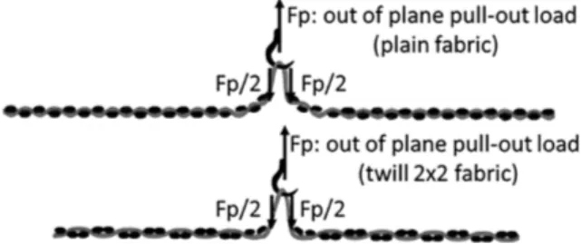
2.3. Out of plane pull-out setup
It is crucial to consider the normal load generated by transversal tows (Fig. 2), the orientation of the tows and the type of woven fabric to determine the fabric cohesion behavior. For this purpose, it is proposed to perform the out of plane pull-out test on a picture frame test set-up, as represented in Fig. 3. This out of plane pull-out technique on a picture frame device was carried out at shear angles susceptible to be found on a highly double curved preforms[19]; i.e. 0°, 15°, 30° and 45°. Similar setup can be found in literature[29]. The used shear frame that was designed at the “Laboratoire Génie de Production de Tarbes” by A. Labanieh et al. (see acknowledgements) in the frame of a regional project has additional features such as the individual control of the yarn tensions together with a dedicated kinematic in order to prevent the bending of tows introduced in classical picture frame designs. These features are essential as they permit to better control the tensions on the transversal tows and thus the applied normal load on the pulled-out
tow. The orientation of the tows is controlled via the in-plane shearing of the device.
Each arm of the frame has a removable needle bed, which allows redirecting the tows in the specified shearing angle (defined by the sheared state of the frame (Fig. 3(c, d)) with limited parasite shearing tensions. This permits to control the orientation of tows with respect to the pulled tow. Each arm has redirection eyelets, in the loading zones (Fig. 3(c)), in order to redirect each tow to a tensioning system and avoid artificial in plane deformation of the tows. In this work, each tow is linked to a weight that can be changed and adapted to control the level of tension in the tow. The resulting tension (especially on the transverse network) plays a significant role in the pull-out load. The needle beds were 3D-printed to the characteristics of each tows and fabrics dimensions.
The samples are cut in a cross-shape manner with 37 × 37 tows (roughly 10 cm × 10 cm central zone) and arms of 70 cm × 10 cm (Fig. 3(b)). The transversal tows in the sample arms are kept in for adding structural stability until the needle bed are mounted on the sample and closed. Then, the sample and the four needle beds are slid inside the shear frame.
Once the sample is well positioned, the shear frame is placed hor-izontally in a tension universal testing machine “INSTRON 400 II®” instrumented with a 500 N load cell. A hook pulls a tow from the center of the sample. It is fixed to the load cell. Weights are attached to all the tows (at the exception of the pulled one) in order to control the ten-sions. The shear frame is indexed at the desired angle using pre-drilled holes marking the distance required for a given angle. The final setup is represented inFig. 3(c). Finally, as the hook goes up, the central tow is pulled from both sides of the sample. The resulting pull-out load on the hook may then be recorded.
The out of plane pull-out test (schematized inFig. 4) was carried out on the samples by pulling out the central tow at a rate of 5 mm/min. Each tow except the pulled out one was put under a tension of 1.04 N/ tow.
Compared to a classical in-plane pull-out test where the recorded load is directly the pull-out load response of a given length L of fabric, in this out of plane pull-out test, the measured load Fp represents twice the response of a fabric of a length of about L/2 majored by the pull-out direction change induced. The pull-out load was recorded for different tests investigating the variation of the following parameters:
- Fabric shear angle: 0°, 15°, 30° and 45°.
- Transversal tension (on carbon tows): 1.04 N/tow and 3.12 N/tow. - Weave patterns (on de-sized flax tows): plain and twill 2 × 2. - Nature of the material (on twill 2 × 2 weaves): de-sized flax and
carbon fiber.
Each test was carried out three times.
3. Experimental results 3.1. Friction tests at the tow scale
The tribological tests are carried out on carbon fiber tows and de-sized flax tows (from twill and plain weave fabrics). The coefficient of friction (COF) is defined as the ratio of the tangential force to the normal loads. The COF, calculated for the three tows, are recorded and plotted against the displacement of the sample holder.Fig. 5represents a sample of the obtained curves for the three tows.
The curves are globally symmetrical against the x axis in the central zone. The negative COF is just due to the fact that the longitudinal load is positive in a direction and negative in the other. On the extremities of the graphs, the COF may be affected by direction changes and device accelerations. The average friction coefficient of each tow was mea-sured at the central zone of the curves (the decreased values due to direction changes were filtered). The average COF was also taken from
Reinforcement Twill 2 × 2
carbon fiber Twill2 × 2 flax Plain flax Fabric properties
Surface density (g/m2) 600 465 458
Warp density (m-1) 380 380 380
Weft density (m-1) 380 430 385
Thickness measured optically: e
(mm)* 1.36 1.43 1.32
Tows properties
Linear density (g/m) 0.813 0.494 0.478 Tensile modulus: E1 (GPa)* 132.7 7.9 7.6 Length of apparent section (pick): Lt
(mm) 5.42 5.26 2.63
Width: b (mm)* 2.60 2.40 2.59
Thickness measured optically on a tow extracted from the fabric: h (mm)*
0.45 0.45 0.45
Diameter of the fiber (µm) 7 20 20
Bending rigidity: Bx (N⋅mm2)* 19.63 1.73 1.67
Table 1
Reinforcement properties (values with a * have been experimentally measured, others are from the manufacturer).
the 10th to 20th cycles to avoid considering the influence of early setup variations and the wear that occurs sometimes after 50/100 cycles. Each material/angle combination was repeated three times on different samples and the average, max and min of the results are displayed in
Fig. 6.
For each tow, four shear angles were tested (0°, 15°, 30°, 45°) as illustrated inFig. 1(d). Theses angles represent the evolution of in-plane shear angles where a setup 0/90° between the upper and lower tows represent the base shear angle of 0°.
3.1.1. Effect of the material on the friction coefficient
At 0° shear angle (Fig. 6), carbon twill shows a friction coefficient of 0.21 with a relatively low dispersion ( ± 0.01) whilst flax twill tow is 24% higher at 0.26 with larger dispersion (−0.04, +0.03) and flax plain tow is even higher than the flax twill with a 52% increase over the carbon tows at a friction coefficient of 0.32 ( ± 0.03).
The dispersion observed on the average friction coefficient of flax tows can be attributed to the un-homogeneous surface of the tows where disordered fibers, not aligned with the others in the main di-rection, may be observed. The color-coded images, of the surfaces of tows prior to the friction test, inFig. 7(a, b and c), obtained using “fixed” upper part load cell upper sample holder “moving” lower part Reciprocating driver lower sample holder
)
b
(
)
a
(
2: sliding part of the holder
1: fixed sample holder
3: guides
4: imbedded nut
5: tensioning bolt
6: intermediate bar
7: compression spring
tow sample
stand
45 mm
50 mm
30 mm
(c)
(d)
Fig. 1. (a) Tribological friction test final setup (bottom moving part and top fixed one), (b) Sample holder fixed on the tribometer, (c) schematic view (bottom part only), (d) considered shear angles. (For interpretation of the references to colour in this figure legend, the reader is referred to the web version of this article.)
pull-out load pulled tow transversal tow transversal load generated normal
OrientationJ [44], an imageJ plugin, represents the orientations of surface fibers on the considered tows. InFig. 7(a, b, c), the direction of the tow represents the 0°. The distribution of angles orientations is summarized in the graph in Fig. 7(d). A certain amount of fibers (normally the vast majority of them) is expected to be in the direction of the tow length. In the flax tows, a little bit of entanglement may be observed due to some false twist given to ensure a small cohesion be-tween the fibers during the flax sliver preparation (up to ± 15°). Up to ± 15°, these fibers can be assumed to be fully imbedded in the tow and consequently harder to dislodge. For higher angles, it is safe to assume that these fibers have a free-floating edge. InFig. 7(d), one can
observe that fiber orientation distribution (from OrientationJ plugin
[44]) is spread all along the orientation range, where carbon fibers have a high percentage of aligned fibers and flax fibers are distributed in all directions. The carbon tows have less disordered free-floating surface fibers (end of fibers/fibrils) as they are mainly manufactured from an assembly of long filaments. Statistically, the longer the filaments, the lower the frequency of end fibers in a certain area. Together with the higher variability of orientation for flax fibers within the tows, this relative homogeneity of the surface explains the lower dispersion in the case of carbon tows. The flax tows show more disordered fibers than carbon on the surface. The abundance of disordered fibers in the flax tows, and particularly in the ones coming from the plain weave fibers seems to cause the dispersion in the flax twill and more in the flax plain COF. The increase of non-aligned fibers also means that fibers have more chances to be entangled and increase the resistance to the sliding movement (Fig. 8). This explains the higher friction coefficient at the end of each cycle for the plain flax (Fig. 5(c)) compared to the twill flax (Fig. 5(b)).
3.1.2. Effect of the weave on the friction coefficient
Another effect of the weave as observed inFig. 7is the abundance of disordered surface fibers. As the tow is more compressed during the
(a)
(b)
Hook
Sample
picture frame
needle bed
redirection eyelet
marked support
for shear angles
weights
pull-out direction
(c)
(d)
Fig. 3. (a) Picture frame unsheared, (b) out of plane pull-out sample, (c) final out of plane pull-out setup, (d) diagram of the out of plane pull-out test. (For interpretation of the references to colour in this figure legend, the reader is referred to the web version of this article.)
weaving process and gets crimped more severely, this tends to expose more surface fibers especially in the case of desized tows with relatively shorter fibers than synthetic ones. As a result, more disordered fibers can cause dispersion in the frictional behavior (can be observed on the dispersion of the flax frictional coefficient) and wear can generate bonds or bridges as shown inFig. 8.
Moreover, as the tows are extracted from woven fabrics, they are undulated because the initially strait tows (before weaving) have a tendency to relax inside the fabric and keep the shape of the imprint from the weave of the fabric. This results in a crimp as illustrated in
Fig. 9. In the central zone of the curves inFig. 5, one can observe crests (better visible in flax towsFig. 5(b, c)). These crests represent the lower tow sliding over a crimp of the upper tow. This effect is less visible for carbon tows as they tend to straighten up outside of the fabric (Fig. 9(a)) while flax tows tend to keep the crimp because the level of permanent deformation is reached during the weaving process even after low bending strains due to fiber entanglement and misaligned fi-bers. Above a permanent deformation level, the rearrangement of the fibers is made difficult due to fiber entanglement and fiber misalign-ments. This has for effect to “lock” the fibers in their deformed position. As the tow is more undulated for the plain weave fabric, the lateral effort is larger than in the case of the twill weave fabric and therefore, it increases the friction coefficient and its dispersion.
Increasing the frequency of the undulation (due to more crimp), and also the depth of the crests leads to an increase in the average friction coefficient. The number of undulations on the plain tows on a same distance is twice the one observed on 2 × 2 twill. It should result in more crests in the friction coefficient curve. However, only one crest can be seen in the plain curve and this is due to the real contact area. As the test is performed, while the sample holder does a movement of 10 mm, the tow effectively moves 8 mm. This is due to the flexibility in the setup as the moving tow gets slightly stretched due to the friction. The 8 mm motion span can be short enough to only see the effect of a single crimp.
3.1.3. Effect of the angle on the tow-tow friction coefficient
For carbon fiber tows, the results obtained inFig. 6are in line with the literature[42]for similar tows and conditions. As the shear angle increases, the friction coefficient increases as well with a noticeable difference being at 45° (5% increase to initial 0° angle). This is ex-plained in the literature by the increase in the contact area between the tows (intimate contact at fiber scale is increased) as the friction is proposed to be mainly governed by adhesion. For flax tows for both weaves, the friction coefficient, at first glance, tends to decrease as the shear angle increases (as opposed to the carbon tows), but the disper-sion delta is high for the flax twill and even higher for the flax plain tows. This makes the trend not valid. The dispersion could result from the observed “randomness” of fibers on the surface; these free end surface fibers could either be entangled and cause a rise in the COF or act as roller bearings and decrease the COF. These two random and antagonist effects increase the variability in the COF and overshadow the effect of tow orientation.
Regarding the increase in contact area, further tests were conducted with two tows placed on independent holders. This meant an increase in the contact area four times over. Tensions and normal loads were adjusted accordingly. Results, reported in Fig. 10, show that quad-rupling the contact area leads to friction coefficient close to that of a single tow, or within the dispersion margin, in good accordance with Coulomb’s friction theory. This suggests that the evolution of the fric-tion coefficient in Fig. 5 comes mostly from the orientation of the surface fibers and how they interact with each other.
3.2. Out of plane pull-out test
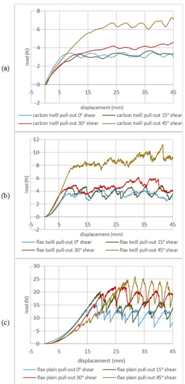
Pull-out load results are presented inFig. 11. The first maximum attained by each of the curves represents the end of the un-crimping
Fig. 5. Friction coefficient during 10th to 20th cycle of the tow to tow friction test for (a) twill carbon tows, (b) twill flax and (c) plain desized up flax tows.
0.22 0.28 0.28 0.26 0.26 0.28 0.33 0.32 0.24 0.22 0.21 0.21 0.1500 0.2000 0.2500 0.3000 0.3500 0.4000 0.4500 0 10 20 30 40 50
flax twill 2x2 shear angleflax plain carbon twill 2x2
COF
Fig. 6. Average COF of all tests of each tow configuration as a function of the shear angles (the error bars represent min and max values in each configura-tion).
and transversal tow rearrangement during the pull-out and represents the maximal pull-out load. After the maximal pull-out load, the tow slides freely inside the fabric. The periodic aspect represents the in-teraction of the residual crimp of the pulled-out tow with the trans-versal tows. The average load in the periodic part is considered as the pull-out load. The average of pull-out loads in each configuration is reported inFig. 12, with error bars reflecting the max and min pull-out loads.
3.2.1. Effect of the material on the out of plane pull-out load
The twill 2 × 2 of carbon fiber and flax fibers have similar di-mensions and were subjected to the same experimental conditions (Fig. 12). Comparing the morphology of the curves inFig. 13, the close-up in pull-out loads, shape of the curve also reveals their behavior. High frequency noise in the signal is due to entanglement and “fiber brid-ging” from free-floating end fibers (more present on flax as seen in
Fig. 4) as opposed to the smoother signal encountered with carbon. When two surface fibers get entangled, they behave like “chain links” increasing COF. The prominent “saw tooth” behavior is due to the crimp “bypassing”. This phenomenon is extremely severe in the case of plain weave flax (due to the frequency and severity of the crimp imprint
as observed inFig. 9) and still present in lesser extent for twill weave flax and even less so for the twill carbon.
Comparing the results of the pull-out to the frictional behavior of the two tows, one can observe that even if the friction coefficient of the flax twill is 25% higher than for the carbon twill at a shear angle of 0°, the average pull-out loads are very close to each other’s. However, when looking closely at the pull-out loads of the two tows (Fig. 13), one
0 1 2 3 4 5 6 -90 -60 -30 0 30 60 90 carbon twill 2x2 flax twill 2x2 flax plain orientation angle % of surfacic fibers (d)
Fig. 7. Color-coded microscopic images of the orientation of surface fibers in (a) carbon twill tows, (b) flax twill tow, (c) flax plain tow and (d) the orientation distribution of the surface fibers on the previously mentioned tows. (For inter-pretation of the references to colour in this figure legend, the reader is referred to the web version of this article.)
Fig. 8. Entanglement of surface fibers observed after the friction test of flax plain tows. (For interpretation of the references to colour in this figure legend, the reader is referred to the web version of this article.)
(a)
(b)
(c)
5 mm
Fig. 9. Tows profile out of the fabric for (a) carbon twill 2 × 2, (b) flax twill 2 × 2, (c) flax plain. (For interpretation of the references to colour in this figure legend, the reader is referred to the web version of this article.)
0.0000 0.0500 0.1000 0.1500 0.2000 0.2500 0.3000 0.3500 0.4000
flax twill flax plain carbon twill
single tow double tow
COF
Fig. 10. Average friction coefficient for single and double tow setups at 0° shear (the error bars represent min and max values in each configuration).
can observe that they replicate the trend of the friction coefficients of their respective tows (Fig. 5(a, b)) as loads recorded on flax tend to get higher crests. This is due to the effect of the residual crimp. As illu-strated in Fig. 9(a, b), even out of the fabric, tows tend to retain a certain undulation. It was observed that the flax tows retain their shape better out of the reinforcement (residual crimp: thickness of the ex-tracted tow from top of the crest to bottom of the trough is 85% of the fabric initial thickness) while the carbon twill tends to straighten out of the reinforcement (residual crimp: 70% of the fabric thickness). The valley in the pull-out curve correspond to configurations “in phase” with the initial configuration of the fabric (the pulled tow is extracted with a distance multiple of the fabric unit cell length); no obstacles are
present nearby and we assume that the load is governed by friction. The values at the valleys (around 3 N for both carbon and flax twill) are in accordance with the tendency observed on the friction coefficients “post direction change” (around 0.2 for each tow). The crests in the curves, representing the effect of the crimp “collision”, is higher on the flax twill (around a COF of 0.4 and 4 N in the pull-out loads) than the carbon twill (around a COF of 0.21 and 3.5 N in the pull-out loads). This explains why the flax twill shows higher loads than the carbon one. 3.2.2. Effect of the weave on the out of plane pull-out load
From the comparison of a twill 2 × 2 with a plain weave for the same material (yarn) and transversal tension loads, one may observe an increase in the out of plane pull-out load by about 280% for a shear angle of 0° (Fig. 12). As illustrated inFig. 13, the change in the weave pattern from twill to plain weave consists mainly in a change in the frequency of crossover points (going from 9 crossover points for 18 transversal tows in the twill weave to 18 crossover points for 18 transversal tows in the plain weave). A crossover point is the position alternation of the warp and the weft. The plain weave possesses twice as many crossover points per tow than the 2 × 2 twill (Fig. 4). The crossover points are the cause of the crimp in the tows. Since the pull-out load is heavily impacted by the crimp of the tows, the pull-pull-out load increases as the frequency of crossover points increases. The increase crimp also increases the severity of contact between the tows, thus increasing the chances of fibers to get entangled and detangled. This has the effect of increasing the COF and the load required to pull-out the tow.
3.2.3. Effect of the transversal tension on the out of plane pull-out load The effect of the transversal tension increase for the carbon twill fabric is shown inFig. 12. An increase of ~200% in the tension of the transversal tows, in the case of the carbon twill, increases the out of plane pull-out load by an average of 100% for 0° shear angle.
In a fabric, two perpendicular tows intertwine creating a bent geometry as represented inFig. 4. The angled tension in the tows, coupled with its bending-induced tension creates a normal load on the crossing tow. Increasing the normal load by increasing the transversal tension, in turn, increases the out of plane pull-out load. A nonlinear behavior was expected since even for un-tensioned fabric, pulling a tow still requires a fair effort. The increase in weaving in the pulled tow, responsible for the pull-out load increase is a result of the competition between the permanent crimp observed on a yarn, the bending beha-vior and the imposed tension. The influence of the tension will reduce as the crimp in transverse tows straightens.
3.2.4. Effect of the shear angle on the out of plane pull-out load
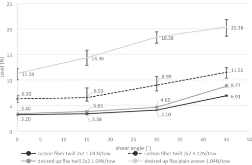
By considering the effect of the shear angle, it is possible to observe, inFig. 12, that an increase in the shear angle increases the pull-out load. Increasing the shear angle from 0° to 15° leads to an increase of the pull-out load by an average of 5% for the carbon fiber fabric in both loads. At the same angles, only an increase of 1% in the respective friction coefficient is observed. For the flax fabrics, an increase of 22% is observed for the twill weave, while the friction coefficient increased by 9%. For the plain weave fabric, an increase of 27% is observed against 2% in the respective friction coefficient.
Going from 15° to 30° further increases the pull-out load to an average of 28% for carbon fabric under a tension of 0.4 N/mm and 40% for the carbon fabric under 1.14 N/mm. For the flax fabric, the friction coefficient only increased by 1%. An increase of 50% for the twill and 60% for the plain weave is observed while both friction coefficient decreased respectively by −1% and −15%.
Finally, getting up to a shear angle of 45° increases the pull-out load to an average of 110% for carbon fabric under a tension of 0.4 N/mm and 90% for the carbon fabric under 1.14 N/mm. As for the friction coefficient, an increase of 2% is observed. For the flax fabric one can observe an increase of the pull-out load of 180% for the twill and 80%
Fig. 11. Typical out of plane pull-out load aspect for 1.04 N/tow tension for (a) carbon twill 2 × 2 weave, (b) flax twill 2 × 2 and (c) flax plain weave. (For interpretation of the references to colour in this figure legend, the reader is referred to the web version of this article.)
for the plain weave even with the friction coefficient still decreasing of 16% for the twill and 6% for the plain.
A nonlinear increase in the pull-out force is observed for the four tested configurations with different trends. One explanation is that the friction of the tow is mainly due to adhesion. The increase of the contact area between tows during shearing might increase the shear strength and thus the tangential load required to slide the tow and so the pull-out load. A quick geometrical estimation of the contact area (going from a square at 0° shear to a rhombus at 45°) yields and increase of 25% in the contact area. As observed by quadrupling the contact area in the friction test, a 25% increase should not affect the pull-out load that much.
Since the pull-out loads and the friction coefficient trends are not necessarily in accordance, other factor that might be of influence is the shear locking phenomenon. As the fabric shears, the tows of the same network (side by side) start to get into contact, adding friction (this is a transitional zone). The in-plane shear continues until it reaches an angle where it becomes too difficult to shear (locking angle). During the out of plane pull-out test, it was observed that the shear angle of the plain flax fabric was lower than the imposed angle. It seems that the plain weave reaches a transitional zone earlier than the other fabrics and is unable to increase at the same rate as the other fabrics. This has been confirmed by other authors using bias and picture frame shearing
tests[45].
4. Conclusion
In this work, experimental investigation of fabric cohesion as a whole and the influence of the frictional behavior of tows in particular has been conducted. First an inter-tow friction test was carried out to determine the friction coefficient of the tows and explore any influence that a change in orientation might have. Then, using a pull-out method the cohesion of the reinforcements was characterized for different configurations. The chosen method consisted of pulling out a tow from the center of a shear frame and to measure the pull-out load. This method allows for a control of the shear angle and the orientation of the tows, the tension (and thus the normal load) applied to the tows, the type of material and weave of the fabric.
As the tow sliding during the shape forming of composite pre-forming is mainly due to decohesion in the reinforcement, the previous tests suggest that the cohesion of a fabric is directly correlated to the pull-out test parameters. An increase in the angle of the tows due to in-plane shear increases the tension required to pull-out tows and there-fore increases the fabric cohesion for in-plane shear angles higher than 15° for plain weaves and 30° for the twill 2 × 2 weave fabric. However, since the increase is nonlinear and mostly takes place above the pre-viously mentioned angles, sliding may not be prevented only by in-plane shear at low shear angles. An increase in the transversal tensions also increases the pull-out load and therefore improves the fabric co-hesion. The increase of the transversal tensions seems to have more effect on lower shear angles and may be overshadowed by the effect of the shear locking at high in-plane shear angles.
The effect of the fabric on the cohesion of the reinforcement de-pends on the friction coefficient of the tow, the fiber lengths and the shear angle. As an example, the flax pull-out load is slightly higher than the equivalent 2 × 2 carbon twill weave while the carbon tows have significantly lower friction coefficient. Though, the observed pull-out load of flax twill as a function of the shear angle does not follow the trend of the single tow. This may be due to disordered fibers on the surface of the tow having more influence on a single tow while its effect gets smoothed over a longer pull-out motion with more contact zones. The type of weave mainly affects the frequency of crossover points. An increase in crossover points either by frequency or by length of the fabric increases the fabric cohesion linearly.
3.20 3.38 4.10 6.91 6.30 6.53 8.99 11.50 3.40 3.83 4.65 8.77 11.28 14.36 18.38 20.38 0 5 10 15 20 25 0 5 10 15 20 25 30 35 40 45 50
carbon fiber twill 2x2 1.04 N/tow carbon fiber twill 2x2 3.12N/tow desized up flax twill 2x2 1.04N/tow desized up flax plain weave 1.04N/tow
shear angle (°)
Load (N
)
Fig. 12. Out of plane pull-out loads (the error bars represent min and max values in each configuration).
Fig. 13. Close up on the pull-out load of the carbon and flax twill 2x2s and flax plain at a shear angle of 0°. (For interpretation of the references to colour in this figure legend, the reader is referred to the web version of this article.)
In order to tackle the appearance of gaps during reinforcement preforming, a weave with high crossover points and tow crimp such as plain weaves should be preferred. A sizing that can increase the imprint depth together with bending stiffness of the tow would also increase the cohesion as it makes it harder for tows to “bypass” the crimp but must be used with care as to maintain the drapabilty of the fabric. While preforming, differential blank holders can be used to vary tensions in certain areas of the reinforcement. Increasing the tension in the tow transversal to the ones expected to slide (in unsheared and low shear zones) will increase cohesion and decrease the apparition of gaps.
For future studies, the results presented in this work could be gathered and used in computational models in order to have a better understanding of the inter-tow frictional behavior and cohesion of the fabric with the objective to improve the forming simulation of textile reinforcement fabrics in the frame of complex shapes.
CRediT authorship contribution statement
M.M. Salem: Conceptualization, Investigation, Visualization,
Validation, Writing - original draft, Writing - review & editing. E. De
Luycker: Conceptualization, Investigation, Writing - review & editing,
Supervision, Project administration. K. Delbe: Methodology, Resources, Writing review & editing. M. Fazzini: Resources, Writing -review & editing. P. Ouagne: Conceptualization, Investigation, Resources, Writing - review & editing, Supervision, Funding acquisi-tion.
Declaration of Competing Interest
The authors declare that they have no known competing financial interests or personal relationships that could have appeared to influ-ence the work reported in this paper.
Acknowledgments
This work was possible thanks to the shear frame developed by Labnieh et al. in the frame of the SEMIR project. The author would also like thank Dr. Jean-Yves Paris and François Grizet for their guidance and support.
References
[1] Tempelman E, Shercliff H, van Eyben BN, Tempelman E, Shercliff H, van Eyben BN. Chapter 10 – Resin Transfer Molding. Manuf. Des., Butterworth-Heinemann; 2014, p. 171–86. Doi:10.1016/B978-0-08-099922-7.00010-X.
[2] Park CH, Il Lee W, Han WS, Vautrin A. Weight minimization of composite laminated plates with multiple constraints. Compos Sci Technol 2003;63:1015–26.https://doi. org/10.1016/S0266-3538(03)00014-9.
[3] Torres M. Parameters’ monitoring and in-situ instrumentation for resin transfer moulding: a review. Compos Part A Appl Sci Manuf 2019;124:105500.https://doi. org/10.1016/J.COMPOSITESA.2019.105500.
[4] Meola C, Boccardi S, Carlomagno G maria. Composite Materials in the Aeronautical Industry. Infrared Thermogr. Eval. Aerosp. Compos. Mater., Woodhead Publishing; 2017, p. 1–24. Doi:10.1016/b978-1-78242-171-9.00001-2.
[5] Geng Y, Jiang J, Chen N. Local impregnation behavior and simulation of non-crimp fabric on curved plates in vacuum assisted resin transfer molding. Compos Struct 2019;208:517–24.https://doi.org/10.1016/J.COMPSTRUCT.2018.10.054. [6] Boisse P, Colmars J, Hamila N, Naouar N, Steer Q. Bending and wrinkling of
composite fiber preforms and prepregs. A review and new developments in the draping simulations. Compos Part B Eng 2018;141:234–49.https://doi.org/10. 1016/J.COMPOSITESB.2017.12.061.
[7] Hübner M, Rocher JE, Allaoui S, Hivet G, Gereke T, Cherif C. Simulation-based investigations on the drape behavior of 3D woven fabrics made of commingled yarns. Int J Mater Form 2016;9:591–9. https://doi.org/10.1007/s12289-015-1245-8.
[8] Rashidi A, Milani AS. Passive control of wrinkles in woven fabric preforms using a geometrical modification of blank holders. Compos Part A Appl Sci Manuf 2018;105:300–9.https://doi.org/10.1016/J.COMPOSITESA.2017.11.023. [9] Allaoui S, Hivet G, Wendling A, Ouagne P, Soulat D. Influence of the dry woven
fabrics meso-structure on fabric/fabric contact behavior. J Compos Mater 2012;46:627–39.https://doi.org/10.1177/0021998311424627.
[10] Nosrat-Nezami F, Gereke T, Eberdt C, Cherif C. Characterisation of the
shear-[11] Boisse P, Hamila N, Guzman-Maldonado E, Madeo A, Hivet G, dell’Isola F. The bias-extension test for the analysis of in-plane shear properties of textile composite re-inforcements and prepregs: a review. Int J Mater Form 2017;10:473–92.https:// doi.org/10.1007/s12289-016-1294-7.
[12] Sjölander J, Hallander P, Åkermo M. Forming induced wrinkling of composite la-minates: A numerical study on wrinkling mechanisms. Compos PART A 2016;81:41–51.https://doi.org/10.1016/j.compositesa.2015.10.012. [13] Lightfoot JS, Wisnom MR, Potter K. A new mechanism for the formation of ply
wrinkles due to shear between plies. Compos Part A Appl Sci Manuf 2013;49:139–47.https://doi.org/10.1016/j.compositesa.2013.03.002. [14] Lightfoot JS, Wisnom MR, Potter K. Defects in woven preforms: Formation
me-chanisms and the effects of laminate design and layup protocol. Compos Part A Appl Sci Manuf 2013;51:99–107.https://doi.org/10.1016/j.compositesa.2013.04.004. [15] Dong Z, Sun CT. Testing and modeling of yarn pull-out in plain woven Kevlar
fabrics. Compos Part A Appl Sci Manuf 2009;40:1863–9.https://doi.org/10.1016/j. compositesa.2009.04.019.
[16] Potter K, Khan B, Wisnom M, Bell T, Stevens J. Variability, fibre waviness and misalignment in the determination of the properties of composite materials and structures. Compos Part A Appl Sci Manuf 2008;39:1343–54.https://doi.org/10. 1016/j.compositesa.2008.04.016.
[17] Zhao C, Xiao J, Li Y, Chu Q, Xu T, Wang B. An experimental study of the influence of in-plane fiber waviness on unidirectional laminates tensile properties. Appl Compos Mater 2017;24:1321–37.https://doi.org/10.1007/s10443-017-9590-z.
[18] Hsiao HM, Daniel IM. Effect of fiber waviness on stiffness and strength reduction of unidirectional composites under compressive loading. Compos Sci Technol 1996;56:581–93.https://doi.org/10.1016/0266-3538(96)00045-0.
[19] Allaoui S, Hivet G, Soulat D, Wendling A, Ouagne P, Chatel S. Experimental pforming of highly double curved shapes with a case corner using an interlock re-inforcement. Int J Mater Form 2014;7:155–65. https://doi.org/10.1007/s12289-012-1116-5.
[20] Salem MM, De Luycker E, Fazzini M, Ouagne P. Experimental, analytical and nu-merical investigation to prevent the tow buckling defect during fabric forming. Compos Part A Appl Sci Manuf 2019;125:105567.https://doi.org/10.1016/j. compositesa.2019.105567.
[21] Tephany C, Gillibert J, Ouagne P, Hivet G, Allaoui S, Soulat D. Development of an experimental bench to reproduce the tow buckling defect appearing during the complex shape forming of structural flax based woven composite reinforcements. Compos Part A Appl Sci Manuf 2016;81:22–33.https://doi.org/10.1016/j. compositesa.2015.10.011.
[22] Ouagne P, Soulat D, Moothoo J, Capelle E, Gueret S. Complex shape forming of a flax woven fabric; analysis of the tow buckling and misalignment defect. J Compos Mater 2013;51A:1–10.https://doi.org/10.1016/j.compositesa.2010.08.011. [23] Iwata A, Inoue T, Naouar N, Boisse P, Lomov SV. Coupled meso-macro simulation of
woven fabric local deformation during draping. Compos Part A Appl Sci Manuf 2019;118:267–80.https://doi.org/10.1016/J.COMPOSITESA.2019.01.004. [24] Ouagne P, Soulat D, Tephany C, Gillibert J. Measurement of the appearance and
growth of tow buckling defect in the frame of complex shape manufacturing process by using fringe projection technique. Strain 2016;52:559–69.https://doi.org/10. 1111/str.12206.
[25] Ouagne P, Soulat D, Hivet G, Allaoui S, Duriatti D. Analysis of defects during the preforming of a woven flax reinforcement. Adv Compos Lett 2011;20:105–8. [26] Beakou A, Cano M, Le Cam JB, Verney V. Modelling slit tape buckling during
au-tomated prepreg manufacturing: a local approach. Compos Struct 2011;93:2628–35.https://doi.org/10.1016/j.compstruct.2011.04.030.
[27] Matveev MY, Schubel PJ, Long AC, Jones IA. Understanding the buckling behaviour of steered tows in Automated Dry Fibre Placement (ADFP). Compos Part A Appl Sci Manuf 2016;90:451–6.https://doi.org/10.1016/j.compositesa.2016.08.014. [28] Allaoui S, Cellard C, Hivet G. Effect of inter-ply sliding on the quality of multilayer
interlock dry fabric preforms. Compos Part A Appl Sci Manuf 2015;68:336–45.
https://doi.org/10.1016/j.compositesa.2014.10.017.
[29] Nosrat Nezami F, Gereke T, Cherif C. Analyses of interaction mechanisms during forming of multilayer carbon woven fabrics for composite applications. Compos Part A Appl Sci Manuf 2016;84:406–16.https://doi.org/10.1016/j.compositesa. 2016.02.023.
[30] Labanieh AR, Garnier C, Ouagne P, Dalverny O, Soulat D. Intra-ply yarn sliding defect in hemisphere preforming of a woven preform. Compos Part A Appl Sci Manuf 2018;107:432–46.https://doi.org/10.1016/J.COMPOSITESA.2018.01.018. [31] Gatouillat S, Bareggi A, Vidal-Sallé E, Boisse P. Meso modelling for composite
preform shaping - simulation of the loss of cohesion of the woven fibre network. Compos Part A 2013;54:135–44.https://doi.org/10.1016/j.compositesa.2013.07. 010.
[32] Mulvihill DM, Smerdova O, Sutcliffe MPF. Friction of carbon fibre tows. Compos Part A Appl Sci Manuf 2017;93:185–98.https://doi.org/10.1016/j.compositesa. 2016.08.034.
[33] Najjar W, Pupin C, Legrand X, Boude S, Soulat D, Dal Santo P. Analysis of frictional behaviour of carbon dry woven reinforcement. J Reinf Plast Compos
2014;33:1037–47.https://doi.org/10.1177/0731684414521670. [34] Ajayi JO. Effects of fabric structure on frictional properties. Text Res J
1992;62:87–93.https://doi.org/10.1177/004051759206200205.
[35] Montero L, Allaoui S, Hivet G. Characterisation of the mesoscopic and macroscopic friction behaviours of glass plain weave reinforcement. Compos Part A Appl Sci Manuf 2017;95:257–66.https://doi.org/10.1016/j.compositesa.2017.01.022. tension coupling of carbon-fibre fabric under controlled membrane tensions for precise simulative predictions of industrial preforming processes. Compos Part A Appl Sci Manuf 2014;67:131–9. https://doi.org/10.1016/j.compositesa.2014.08. 030.
[36] Valizadeh M, Ravandi SAH, Salimi M, Sheikhzadeh M. Determination of internal mechanical characteristics of woven fabrics using the force-balance analysis of yarn pullout test. J Text Inst 2008;99:47–55.https://doi.org/10.1080/
00405000701567712.
[37] Das S, Jagan S, Shaw A, Pal A. Determination of inter-yarn friction and its effect on ballistic response of para-aramid woven fabric under low velocity impact. Compos Struct 2015;120:129–40.https://doi.org/10.1016/j.compstruct.2014.09.063. [38] López-Gálvez H, Rodriguez-Millán M, Feito N, Miguelez H. A method for inter-yarn
friction coefficient calculation for plain wave of aramid fibers. Mech Res Commun 2016;74:52–6.https://doi.org/10.1016/j.mechrescom.2016.04.004.
[39] Cornelissen B, Rietman B, Akkerman R. Frictional behaviour of high performance fibrous tows: Friction experiments. Compos Part A Appl Sci Manuf 2013;44:95–104.
https://doi.org/10.1016/j.compositesa.2012.08.024.
[40] Cornelissen B, Sachs U, Rietman B, Akkerman R. Dry friction characterisation of carbon fibre tow and satin weave fabric for composite applications. Compos Part A Appl Sci Manuf 2014;56:127–35.https://doi.org/10.1016/j.compositesa.2013.10. 006.
[41] Tourlonias M, Bueno MA, Poquillon D. Friction of carbon tows and fine single fi-bres. Compos Part A Appl Sci Manuf 2017;98:116–23.https://doi.org/10.1016/j. compositesa.2017.03.017.
[42] Tourlonias M, Bueno MA, Fassi G, Aktas I, Wielhorski Y. Influence of friction angle between carbon single fibres and tows: Experimental analysis and analytical model. Compos Part A Appl Sci Manuf 2019;124:105478. Doi:10.1016/j.compositesa. 2019.105478.
[43] Peirce FT, Peirce FT. The “Handle” of cloth as measurable quantity. J Text Inst Trans 1964;55:516–30.https://doi.org/10.1080/19447015508664900. [44] Rezakhaniha R, Agianniotis A, Schrauwen JTC, Griffa A, Sage D, Bouten CVC, et al.
Experimental investigation of collagen waviness and orientation in the arterial adventitia using confocal laser scanning microscopy. Biomech Model Mechanobiol 2012;11:461–73.https://doi.org/10.1007/s10237-011-0325-z.
[45] Lomov SV, Boisse P, Deluycker E, Morestin F, Vanclooster K, Vandepitte D, et al. Full-field strain measurements in textile deformability studies. Compos Part A Appl Sci Manuf 2008;39:1232–44.https://doi.org/10.1016/j.compositesa.2007.09.014.