HAL Id: tel-00005738
https://pastel.archives-ouvertes.fr/tel-00005738
Submitted on 5 Apr 2004HAL is a multi-disciplinary open access archive for the deposit and dissemination of sci-entific research documents, whether they are pub-lished or not. The documents may come from teaching and research institutions in France or abroad, or from public or private research centers.
L’archive ouverte pluridisciplinaire HAL, est destinée au dépôt et à la diffusion de documents scientifiques de niveau recherche, publiés ou non, émanant des établissements d’enseignement et de recherche français ou étrangers, des laboratoires publics ou privés.
Robert Bestak
To cite this version:
Robert Bestak. Les mécanismes de fiabilisation (protocoles ARQ) et leur adaptation dans les réseaux radiomobiles de 3G. Traitement du signal et de l’image [eess.SP]. Télécom ParisTech, 2003. Français. �tel-00005738�
Thèse
présentée pour obtenir le grade de docteur de l’Ecole Nationale Supérieure des Télécommunic ations
Spécialité : Informatique et Réseaux
Robert BESTAK
Les mécanismes de fiabilisation (protocoles ARQ) et
leur adaptation dans les réseaux radiomobiles de 3G
Soutenue le 18 décembre 2003 devant le jury composé de
Xavier LAGRANGE Président
Khaldoun AL AGHA Rapporteurs
Laurent TOUTAIN
Philippe MARTINS Examinateurs Boris SIMAK
Jérôme BROUET Invités
Rémy ROGACKI
v
Remerciements
Tout d’abord, je tiens à remercier mon directeur de thèse le professeur Philippe Godlewski. Ses conseils et ses crit iques constructives m’ont beaucoup apporté tout au long de ces années. Je lui suis très reconnaissant pour sa patience et ses efforts à me guider durant ma formation scientifique.
Un grand merci aux maîtres de conférences Philippe Martins et Elie Najm qui ont contribué largement à ma formation. J’ai beaucoup apprécié nos discussions techniques qui m’ont orienté vers le but de ma recherche.
Je remercie les rapporteurs de ma thèse, Khaldoun Al Agha et Laurent Toutain, d’avoir consacré de leur temps à ma thèse et d’avoir apporté des remarques constructives. Je tiens à remercier les autres membres du jury dont Xavier Lagrange, Boris Simak, Jérôme Brouet et Rémy Rogacki de leurs commentaires pertinentes.
Je remercie tous les enseignants et thésards du Département Infres de l’ENST pour avoir créé une ambiance amicale et sympathique. Je remercie tout particulièrement mes amis avec qui j’ai partagé le bureau durant la thèse Tatiane Aubonnet, Arnaud Bailly, et Alexandre Tau-veron qui m’ont donné leur soutien durant cette thèse.
Un grand merci aux étudiants de l’ENST qui m’ont permis d’enrichir mes connaissances au cours de l’encadrement des projets.
Je voudrais exprimer ma gratitude à mon entourage personnel, mes parents et mes amis qui m’ont encouragé tout au long de mes études en France, sans lesquelles je n’aurai pas finalisé cette thèse.
vii
Résumé
Les réseaux radiomobiles de 3ème génération (3G), tel que l’UMTS (Universal Mobile Tele-communications System ), ont été prévus, dés le début de leur conception, pour offrir un mode paquet aussi bien qu’un mode circuit; le mode circuit étant le mode unique de la 2G (cas du système GSM, Global System for Mobile communications).
Pour fiabiliser les transmissions de données en mode paquet, il faut mettre en œuvre des protocoles disposant de la technique ARQ (Automatic Repeat reQuest ). L’objet de cette thèse est l’étude de protocoles ARQ qui peuvent être activés dans l’architecture protocolaire globale de l’UMTS. Cela nous amène à étudier les couches contenant les protocoles ou entités suivan-tes : RLC (Radio Link Control), TCP (Transmission Control Protocol) et MAC -hs (Medium Access Control-high speed). L’étude des nouvelles caractéristiques des protocoles ARQ de l’UMTS ainsi que la poss ibilité de leur enrichissement est effectuée. L’empilement des méc a-nismes ARQ présente des risques d’interactions dont certains sont analysés.
Le chapitre 1 présente le contexte de notre étude. Le lecteur est familiarisé aux innovations et notations de l’UMTS qui sont reprises dans les chapitres suivants. L’architecture de l’interface radio de l’UMTS et ses différents aspects sont présentés dans le paragraphe 1.2; la présentation concerne principalement l’architecture d’un point de vue protocolaire. Suite à cette présentation de l’architecture de l’UMTS dans son ensemble, le paragraphe 1.3 introduit les trois protocoles ARQ ainsi que les éléments réseaux entre lesquels ces protocoles fonctio n-nent (figure 4). L’étude détaillée de ces protocoles est faite dans les chapitres suivants. Suivant l’exigence aux délais et la sensibilité aux erreurs, les services de l’UMTS sont divisés en quatre classes. Celles -c i sont présentées dans le paragraphe 1.4.
La transmission fiable de données sur l’interface radio de l’UMTS est principalement réali-sée par le protocole RLC, plus précisément par les entités RLC qui fonctionnent en mode ac-quitté (AM, Acknowledged mode). Le protocole est largement adaptable et des primitives spé-cifiques permettent de l’ajuster confo rmément à la qualité de service requise. Dans le paragra-phe 2.3, nous analysons différents aspects des mécanismes du protocole RLC, comme la fonc-tion SDU discard. Le protocole RLC de l’UMTS a été amélioré et enrichi par rapport au proto-cole RLC du (E)GPRS (Enhanced, General Packet Radio Service). Certaines des différences entre elles sont mentionnées dans le paragraphe 2.5. Le chapitre 2 est terminé par des remar-ques concernant l’implementation des protocoles (le paragraphe 2.6).
Nombre de services prévus pour l’UMTS sont proches des services offerts par l'Internet fixe (comme le web-browsing, la messagerie électronique, etc.). Ces services sont fournis via la pile protocolaire TCP/IP, base traditionnelle et obligatoire du monde Internet. L'utilisation de TCP/IP sur une interface radio a donné lieu à de nombreuses études mais seulement une partie considère une couche liaison avec un ARQ. Les mécanismes TCP sont comparés avec ceux du RLC de l’UMTS dans le paragraphe 3.4. Le paragraphe 3.5 analyse l’utilité de certaines propo-sitions du TCP pour les réseaux sans fil comme Split-TCP, Wirless-TCP, Snoop , etc., dans l’environnement de l’UMTS.
L’introduction du protocole RLC au -dessous de la pile protocolaire TCP/IP est utile pour la performance globale. La grande flexibilité du RLC conduit à une longue liste de paramètres ajustables, tels que les temporisateurs, la fenêtre d’émission, le nombre maximum de tentatives de réémissions d’un bloc RLC, etc. Un de ces paramètres spécifie la taille de la mémoire tam-pon (buffer) en entrée de la couche RLC. Nous étudions l’impact des différents soft states du protocole TCP sur l’occupation du tampon de l’entité RLC doit être pris en compte.
L’occupation de ce tampon affecte le TCP RTT (Round Trip Time). Il faut distinguer les transmissions de données : (i) en voie montante et (ii) en voie descendante. Dans le premier cas, l’occupation du tampon de l’entité RLC (situé dans l’UE, User Equipment) est déterminé par le système d'exploitation d’UE et le contrôle interne de flux entre les protoco les RLC et TCP en plus des soft states du TCP. Notre étude considère uniquement le deuxième cas (voie descendante) où le contrôle interne de flux entre les deux protocoles n’existe pas. L’occupation du tampon de l’entité RLC (RNC, Radio Network Controller), en considérant différentes va-leurs du RTT dans le réseau fixe et du BlER (Block Error Rate, taux d’erreurs par bloc) sur la liaison radio sont analysées dans le paragraphe 4.3. De plus, les diverses tailles du tampon de l’entité RLC sur la performance du protocole TCP sont étudiées.
Pour surmonter quelques inconvénients de l’empilement TCP/RLC, dans le paragraphe 4.4.1, nous proposons d’introduire entre les deux protocoles un mécanisme spécifique appelé Early Error Notification (EEN). Celui-ci est basé su r la fonction SDU discard du RLC et sur la possibilité d’échanger des messages de contrôle entre les protocoles TCP et RLC. Les résultats de simulations sans et avec l’EEN sont présentés dans le paragraphe 4.4.2. Le mécanisme EEN est suggéré pour les transmissions de données en voie montante. La possibilité d’utilisation de l’EEN en voie descendante est étudiée dans le paragraphe 4.4.3.
Pour améliorer les performances des transmissions de données en voie descendante, la Re-lease 5 de l'UMTS propose un nouveau mode d'accès, HSDPA (High Speed Downlink Packet Access). Le mode HSDPA introduit un mécanisme hybride ARQ (HARQ) qui concerne les ni-veaux physique et MAC (localisé au Node B). Ce mécanisme, basé sur le Stop&Wait ainsi sur une numérotation spécifique, est analysé dans le par agraphe 5.2.
Résumé ix
Le mode d’allocation du HSDPA est très flexible. Néanmoins, des services comme le streaming n’ont pas besoin d’une telle allocation dynamique. Les services de streaming génè-rent un flux sortant régulier de données. Pour un tel flux de données, il est plutôt envis ageable d’allouer périodiquement des ressources radio. L’impact de l’allocation périodique sur l’allocation dynamique est étudié dans le paragraphe 5.3.
La majorité des études sur l’HSDPA concerne l’adaptation rap ide du lien radio, la perfor-mance d’Error Correction Code ou les politiques d’allocation de ressources radio. En ce mo-ment, peu d’études s’intéressent aux mécanismes du protocole MAC-hs. Les mécanismes du protocole MAC-hs sont liés avec la procédure de l’adaptation rapide du lien radio à la couche physique. Par rapport au contexte traditionnel du CDMA, l’adaptation rapide du lien radio de l’HSDPA n’est pas faite par l'intermédiaire d’un contrôle de puissance. Au lieu de cela, une pa-lette de schémas de modulation-codage (MCS, Modulation Coding Scheme) est introduite et le choix du schéma MCS est continuellement ajusté selon les conditions radio courantes. Dans le paragraphe 5.4, nous proposons d’enrichir la procédure d’adaptation de la liaison de l’HSDPA en introduisant un possible fractionnement des blocs lors d'une retransmission. L’impact de cet enrichissement aussi bien sur l’administration du processus HARQ que sur la numérotation spécifique utilisée par le protocole MAC-hs sont étudiés.
Le chapitre 6 présente nos conclusions et désigne quelques directions pour nos futurs tra-vaux et recherches.
xi
Abstract
The UMTS 3G system (3rd generation cellular system) is designed to offer a packet switched mode for data transfers in parallel to a circuit switched mode. This feature was planned since the beginning of 3G studies, contrary to 2G ones (such as the GSM system).
To provide reliable data transfers, protocols implementing ARQ (Automatic Repeat re-Quest) techniques are needed. In UMTS, up to three ARQ protocols can simultaneously be ac-tive at different levels of the protocol architecture. In this thesis, we focus on RLC (Radio Link Control), TCP (Transmission Control Protocol) and MAC-hs (Medium Access Control-high speed) protocols. The stacking of ARQ mechanisms represents a risk of interactions between them. We study studies some of these interactions.
Reliable data transfers on the UMTS radio interface are provided by the RLC protocol, pre-cisely through RLC entities that are configured to operate in an acknowledged mode (AM). The RLC protocol is highly adaptable and specific primitives allow the tuning of the protocol for different QoS requirements. We study different aspects of the RLC mechanisms such as a SDU discard function.
Number of UMTS services are expected to be close to Internet applications such as, web-browsing, e-mail, file transfer, etc. In Internet, these services are provided via the traditional and imperative TCP/IP stack. Protocol mechanisms of TCP are compared with RLC ones. Only a part of TCP extensions for wireless networks consider a radio link with an ARQ protocol at layer 2. We analyze the TCP behavior over RLC and we discuss the usefulness of some of the proposed TCP extensions when used in the UMTS environment.
The introduction of RLC below the TCP/IP stack is useful for the overall performance; however RLC parameters have to be carefully set up. High flexibility of RLC leads to a long list of adjustable RLC parameters. One of signific ant parameters is the buffer size of the con-sidered RLC entity. Impact of different TCP protocol soft states on the RLC buffer occupancy has to be considered. We investigate how the RLC buffer occupancy changes for different val-ues of wired RTT (Round Trip Time) and BlER (Block Error Rate) on the radio interface. In addition, we an alyze the impact of different RLC buffer sizes on the TCP performance. To overcome some drawbacks of TCP/RLC stacking, we propose to introduce between RLC and TCP a specific mechanism called Early Error Notification (EEN). The EEN mechanism is based on the RLC SDU discard function and on a capability of exchanging control messages between TCP and RLC entities. The EEN mechanism is proposed for uplink data transfers. A possibility of using EEN for downlink data transfers is also discussed.
Release 5 of UMTS specifications introduces for downlink data services a new mode called HSDPA (High Speed Downlink Packet Access). When updating the UMTS radio interface with HSDPA, a hybrid ARQ mechanism is introduced at the physical and MAC -hs layers. The ARQ mechanism of HSDPA, which is based on the Stop&Wait method and a specific number-ing, is analyzed. The allocation mode of HSDPA is very flexible. However, services such as streaming services do not need such dynamic allocation of HSDPA resources. We investigate impact of periodic allocation on the dynamic allocation mode. In comparison with the tradi-tional CDMA context (IS95, WCDMA), the link adaptation in HSDPA is not provided through a fast power control. Instead of it, modulation and coding schemes are continuously adjusted according to currently known radio channel conditions. In our work, we propose to enrich the HSDPA link adaptation scheme by introducing fragmentation of blocks, if necessary, during their retransmission attempts. We study impact of this enrichment on the MAC-hs protocol.
Compared to 2G systems, UMTS reinforces the radio link with new technologies and fea-tures such as more elaborated ARQ protocols. However, this reinforcement goes with a risk of accumulation of mechanisms. Harmonization of these mechanisms are challenges for the next generation of cellular systems (beyond 3G, 4G, …).
Contents xiii
Contents
Remerciements (in French) ... v
Résumé (in French) ...vii
Abstract ...xi
Contents ...xiii
Chapter 1 Introduction of ARQ protocols in UMTS ...1
1.1 Introduction...1
1.2 Architecture of UMTS radio access network...1
1.2.1 Components and features of UTRAN...3
1.2.2 Protocol architecture of UTRAN ...4
1.2.3 Radio Resource Control (RRC)...6
1.2.4 Radio bearers ...8
1.2.5 Transport channels for packet transfers ...8
1.3 ARQ techniques in UMTS ... 10
1.4 UMTS QoS Classes... 11
1.5 Context and structure of the thesis...13
1.5.1 Studied features and related works... 13
1.5.2 Struc ture of the thesis ... 14
Chapter 2 Radio Link Control ...17
2.1 Introduction... 17
2.1.1 Reliable mechanisms ... 17
2.1.2 Overview of data link protocols providing reliable transfers ... 18
2.2 Basic fact about RLC of UMTS ... 19
2.2.1 RLC Modes ... 19
2.2.2 Types of RLC blocks and their structures ... 21
2.3 Management of QoS at the RLC layer... 23
2.4 Interlayer interfaces between RLC and adjacent layers ...27
2.4.1 Different types of primitives ... 27
2.4.2 Upper layer/RLC (AM entity) ... 28
2.4.3 RLC/MAC ... 29
2.5 Some of differences between RLC of (E)GPRS and UMTS ...32
2.6 Remarks concerning protocol implementations ... 32
2.6.1 Specification and development of protocols ... 33
2.6.2 C versus Java ... 33
Chapter 3 Transmission Control Protocol in cellular networks...35
3.1 Introduction... 35
3.2 Basic facts about TCP ...35
3.2.1 TCP soft states: slow start and congestion avoidance ... 36
3.2.2 Detection of a segment loss ... 37
3.3 Stream Control Transmission Protocol...40
3.4 Comparison of TCP and RLC (AM entity)...40
3.5 TCP over the UMTS radio interface ...45
3.5.1 Overview of TCP extensions for wireless networks ... 45
Chapter 4 Study of interactions between TCP and RLC in UMTS ...51
4.1 Introduction... 51
4.2 Congestion and error notification in IP networks... 52
4.2.1 Internet Control Message Protocol... 52
4.2.2 Explicit Congestion Notification ... 52
4.3 RLC buffer in a TCP connection path ... 53
4.3.1 Simulation environment... 53
4.3.2 Simulation and discussion ... 57
4.3.3 RLC buffer in a TCP connection path – conclusions ... 67
4.4 Cooperation of RLC and TCP ...67
4.4.1 Early Error Notification (EEN) - uplink ... 68
4.4.2 Simulation and discussion - uplink... 71
4.4.3 The EEN mechanism - downlink... 75
4.4.4 Cooperation of RLC and TCP – conclusions... 77
Chapter 5 High Speed Downlink Packet Access in UMTS ...79
5.1 Introduction... 79
5.2 Architecture of HSDPA ...80
5.2.1 Impact of HSDPA on the radio protocol layers ... 80
Contents xv
5.2.3 MAC-hs entity ... 82
5.3 Study of the HSDPA allocation mode ...87
5.3.1 Basic features of the HSDPA allocation mode... 87
5.3.2 Periodic allocation mode ... 90
5.3.3 Periodic allocation mode - simulation ... 91
5.3.4 Study of the HSDPA allocation mode – conclusions ... 93
5.4 Link adaptation in HSDPA ...94
5.4.1 Link adaptation procedure – standard procedure... 94
5.4.2 Link adaptation procedure – proposed modifications... 95
5.4.3 Simulation environment and parameter setting ... 97
5.4.4 Simulation...100
5.4.5 Link adaptation in HSDPA – conclusions...102
Chapter 6 Conclusions and perspectives...103
6.1 Conclu sions ...103 6.2 Perspectives...105 Abbreviations 107 Publications 111 References 113 3GPP specifications ...113 RFC specifications...114
1
Chapter 1
Introduction of ARQ protocols in UMTS
1.1 Introduction
A boom in cellular networks and Internet characterizes the last decade. Rapid advances in these two areas resulted in increasing demands of mobile users for Internet oriented applic a-tions. Thus, the provision of data packet transfer over the radio interface becomes more and more important for mobile operators. This trend has been taken into account while planning 3rd generation cellular systems (3G).
Compared to 2G, 3G systems are designed to offer a packet -switched mode for data transfer in parallel to a circuit switched mode since the beginning of 3G studies. This is one of signifi-cant features of 3G systems, besides others. In our work, we consider the Europe version of 3G that is denoted as Universal Mobile Telecommunication System (UMTS).
To provide reliable data transfers, protocols implementing ARQ (Automatic Repeat re-Quest) techniques are needed. This thesis studies ARQ protocols that can be found at the global UMTS protocol architecture: RLC (Radio Link Control), TCP (Transmission Control Protocol) and MAC -hs (Medium Access Control-high speed). Compared to 2G systems, the UMTS ARQ mechanisms are more elaborated and they include new interesting features. It is worthwhile to analyze the corresponding ARQ protocols and their relation with the ARQ of TCP since number of UMTS services is expected to be provided via the Internet TCP/IP stack. Our work focuses on the flexibility of the protocols and interactions b etween them.
This introductory chapter familiarizes the reader with some UMTS innovations that are ex-ploited in following chapters. Section 1.2 presents the architecture of UMTS radio access net-work. In section 1.3, we detail ARQ protocols in the global UMTS architecture. Different types of UMTS QoS classes are briefly described in section 1.4. Section 1.5 presents the context of the thesis and gives overview of the dissertation.
1.2 Architecture of UMTS radio access network
Evolution of GSM towards UMTS
One of the most successful and widely used a 2G system in Europe, as well as in other parts of the world, represents the GSM system (Global System for Mobile communication, see e.g., [LG99]). The first GSM network was launched in the first half of 1990s. By 2001, the GSM system represented 70% of the world's wireless market.
The main objective of GSM was to provide mobile users with voice telephony and interna-tional roaming services. Data rates in GSM were limited. The orig inal GSM system was just offering a 9,6 kbit/s user data rate; later on, this rate was increased to 14,4 kbit/s. A growing in-terest of mobile users about data oriented services pushed mobile operators to introduce several new advanced tec hnologies into the GSM architecture; such as HSCSD (High Speed Circuit Switched Data), GPRS (General Packet Radio Service) or EDGE (Enhanced Data Rates for GSM Evolution). These enhancements gradually allowed mobile oper ators to increase data rates from 14,4 kbit/s up to 384 kbit/s in EDGE ([ST01]). This data rate corresponds to the ex-pected data rate in UMTS for wide area; it is assumed up to 2 Mbit/s data rates for micro-cells and indoor UMTS environments.
Major features of UMTS
In comparison with 2G systems, UMTS provides mobile users with several new features. We have already mentioned the introduction of the packet -switched mode at the initial studies of UMTS. Furthermore, the UMTS system offers a mobile user to establish and manage sev-eral radio connections (or radio bearers) at the same time. Thus, a mobile user can simultane-ously make use several different services. For example, a user can rapidly download a file from Internet while running a video teleconference.
Another important UMTS feature is a high adaptability of radio bearers. Properties of a ra-dio bearer can be negotiated and configured according to the service that the given rara-dio bearer supports. UMTS will provide users with a wide range of applications that have different QoS (Quality of Services) requirements; different types of UMTS QoS classes are discussed in sec-tion 1.4. Since it is not possible nowadays to predict the nature and use of many of future ap-plications, it is neither reasonable to optimize the UMT S architecture for only set of applic a-tions. Therefore, UMTS specifications are conceived to be generic to allow good support for existing applications and to facilitate the integration of new applications. The UMTS stan-dardization body is called Third Generation Partnership Project (3GPP). So far, several releases of UMTS (or 3GPP) specific ations have been published: Release 99, Release 4 and Release 5. Our studies are based on R elease 5, which appeared in 2002.
A part of UMTS services are expected to be Internet applications such as, web -browsing, e-mail, file transfer, etc. In Internet, these services are provided via the traditional and imperative TCP/IP stack (Transmission Control Protocol/Internet Protocol). Thus, in addition to the UMTS ARQ technique at the 2nd layer 2 (RLC) and/or at the 1st/2nd layer (MAC-hs), we find at the global UMTS protocol architecture as well the ARQ of TCP at the 4t h layer (transport layer). Before detailing these ARQ techniques, we will describe the UMTS radio access work (UTRAN). The description mainly focuses on the protocol layer architecture of this net-work.
Chapter 1: Introduction of ARQ protocols in UMTS 3
1.2.1 Components and features of UTRAN
The UMTS architecture (see e.g., [HT00], [ST01] or [L01]) is decomposed into two major parts: Core Network or CN and UMTS Terrestrial Radio Access Network or UTRAN (figure 1). This thesis is interested in the radio access network.
The UTRAN consists of one or more Radio Networks Sub-system (RNS). A RNS is further composed of one Radio Network Controller entity (RNC) and of one or more entities called Node Bs. A RNC entity (respectively Node B) corresponds to the Base Station Controller en-tity or BSC (respectively Base Transceiver Station or BTS) in the GSM network.
A RNC entity controls functions related to the UMTS radio interface such as admission con-trol, radio resource concon-trol, power concon-trol, etc. Studies concerning these issues have been sub-ject of many works and can be found for example in [P01], [K01], [M00a] or [N01]. In addi-tion, the RNC entity manages protocol exchanges on Iu, Iur, and Iub interfaces (see figure 1).
A Node B performs functions relevant to the physical layer processing; e.g., coding and in-terleaving, spreading/dispreading, modulation/demodulation, rate adaptation, physical meas-urements, etc. This network entity also performs some basic radio resources management op-erations such as softer handover or close loop power control.
The Time Division Multiple Access (TDMA) technique utilized in the GSM/GPRS system is replaced in UMTS by Wideband Code Division Multiple Access (WCDMA) tec hnique. User information bits are spread over a 5 MHz wide bandwidth by mu ltiplying the user data with quasi-random sequence bits (chips) that is derived from spreading codes.
Figure 1. Network components of UMTS architecture ([ST01]).
Node B Node B SGSN HLR UE Internet, ect. ISDN, ect. RNC GGSN MSC/ VLR RNC GMSC
UMTS Radio Access Network Core Network External networks
Iu Iub
Iur Uu
UE User Equipment RNC Radio Network Control
MSC Mobile Switch Centre VLR Visitor Location Register HLR Home Location Register
GMSC Gateway MSC
SGSN Serving GPRS Support Node GGSN Gateway GPRS Support Node
Both Frequency Division Duplex (FDD) and Time Division Duplex (TDD) modes are sup-ported by the WCDMA technique. The FDD mode uses different 5 MHz frequency bands for the downlink transmission (i.e. from a Node B to a UE entity; we also use a label ↓ for downlink) and for the uplink transmission (i.e. from a UE to a Node B; ↑). In a case of the TDD mode, the same frequency bandwidth is used for both directions (downlink, uplink). Our studies co nsider just the FDD mode.
1.2.2 Protocol architecture of UTRAN
The UTRAN layer architecture (see e.g., [3G25301] or [HT00]) consists of several layers and sub -layers (figure 2); in the rest of the thesis, we employ the term layer to mean as layer as sub-layer:
1. Physical layer (Phy) 2. Data link lay er
a. Medium Access Control (MAC) b. Radio Link Control (RLC)
c. Packet Data Convergence Protocol (PDCP) d. Broadcast /Multicast Control (BMC) 3. Network layer
a. Radio Resource Control (RRC)
Figure 2. The UMTS radio protocol stack in a UE resp ectively in an RNC entity ([HT00]). Physical Layer (Phy)
Medium Access Control (MAC)
Transport channels Logical channels user plane BMC PDCP control plane
Radio Resource Control (RRC)
control
Radio Link Control (RLC)
Chapter 1: Introduction of ARQ protocols in UMTS 5
As in other telecommunication networks, the UTRAN architecture distinguishes two planes: user and control. The user plane handles user messages, whereas the control plane manages control (or signaling) messages.
Higher layer, such as Call Control (CC), Mobility Management (MM) or Session Manag e-ment (SM) are transparent to the radio access network and they are not discussed in our next work.
Physical layer
The physical layer ([3G25212], [3G25302]), located in a Node B, supports the WCDMA tec hnique. The layer offers services to the above MAC layer via radio transport channels. A transport channel is characterized by the size of transported blocks and by physical parameters. Transport channels are unid irectional.
A basic radio frame period of 10 ms (corresponding to 15 slots) is considered at the physical level. A radio transport channel can use a small multiple of the basic radio frame period dura-tion to transmit a data unit of the MAC layer (transport block). The corresponding period is called Transmission Time Interval (TTI), where TTI ∈ (10, 20, 40, or 80 ms). Small values of TTI are used for real time services (e.g., voice), whereas large values of TTI are configured for non-real time services (e.g., file transfers).
Medium Access Control
The MAC layer ([3G25321]) offers services to the RLC layer via logical channels that are classified into control and traffic channels. Logical control channels (respectively traffic chan-nels) convey information originating from the control plane (respectively from the user plane). Parameters associated with a logical channel depend on the type of supported service; e.g., voice, video, signaling messages, etc.
One of MAC tasks is to schedule RLC blocks from different logical channels (i.e. from dif-ferent RLC entities) according to physical constraints and QoS requirements. Furthermore, MAC is responsible for mapping data of logical channel(s) onto the appropriate transport channel(s) and vice versa. This means that the layer multiplexes (de-multiplexes) data to (from) transport channels.
The MAC is constituted of several MAC entities; the initial release of 3GPP (Release 99) specified three types of MAC entities. Each MAC entity is designated to handle specific trans-port channel(s):
(i) MAC-b for broadcast channel, (ii) MAC-d for dedicated channels,
To enhance the downlink packet data performance in UMTS, Release 5 of 3GPP introduced a new mode called High Speed Downlink Packet Access (HSDPA). With this mode, a forth type of MAC entity, called MAC-hs (MAC-high speed), was specified at the MAC layer. The MAC-hs entity handles a new transport channel of HSDPA called HS-DSCH (for more see section 1.2.5). To the HSDPA concept is dedicated chapter 5.
Radio Link Control
The RLC layer ([3G25322]) mainly provides segmentation of higher layer units into units (blocks) that are more suitable for transmission over the air interface. The receiver side then re-sembles radio blocks into original higher layer units and delivers them to the upper layer. If configured, RLC ensures flow control and reliable data transfer between the UE entity and the RNC entity. Retransmission scheme of RLC is based on the ARQ technique type Selective Re-peat. The RLC layer is discussed in more details in chapter 2.
Packet Data Convergence Protocol
The PDCP layer ([3G25323]) just exists in the user plane. The role of PDCP is to provide an header compression (respectively decompression) of IP packets, e.g., the compression of the 40 bytes of TCP/IP headers. The header compression allows utilizing scarce radio resources more effectively when transmitting IP packets over the radio interface. The PDCP compression stems from a fact that few TCP/IP header fields changing from one IP packet to another and the rest of header fields remain more or less the same.
The PDCP standard specifies several compression algorithms that can be utilized. Perform-ance studies of different header compression schemes over wireless links (respectively over the UMTS radio link) can be found in [CA99] (respectively in [RG01]).
Broadcast/Multicast Control
Likewise PDCP, the BMC layer ([3G25324]) only handles data originating from the user plane. The BMC controls transmissio ns of Cell Broadcast Center messages over the UMTS ra-dio interface.
1.2.3 Radio Resource Control (RRC)
The RRC layer (see e.g., [3G25331], [JC01], [TC02]) is the most complex layer in the UMTS radio protocol stack. The RRC can be seen as a “chief” layer at the UTRAN architec-ture.
The principal function of RRC is management of connection(s) between the UE and RNC entity. Layer signaling messages of MM, CM, SM, etc. are encapsulated into RRC messages before transferring them over the UMTS radio interface.
Chapter 1: Introduction of ARQ protocols in UMTS 7
The RRC establishes, modifies and releases protocol entities of the lower layers (Phy, MAC, RLC, etc.). This layer management is provided through control interfaces that are speci-fied between RRC and every lower layer (figure 2). For example, RRC configures MAC trans-port formats, mode of an RLC entity, PDCP compression alg orithm, etc.
Through the control interfaces, RRC also commands lower layers to perform certain types of measurements and to get measurement results back. For example, RRC may ask a lower layer to measure signal to interference ratio in a UE or to measure the Round Trip Time (RTT) between UE and RNC, etc. If an unexpected event occurs at any of the lower layer, the event is reported through the control interface to RRC, which takes the next steps. The RRC/RLC con-trol interface is depicted in more details in section 2.4.4.
Figure 3 shows RRC states and transitions among them: (a) Paging, (b) Broadcast, (c) Ded i-cated control and (d) Active.
Figure 3. Different RRC states and transitions among them ([TC02]).
Paging: is a low-power standby state in which a UE periodically listens to a paging channel. In this state, no dedicated physical channel is allocated to the UE. Effectively, no up-link/downlink data transfers are possible in this state.
Broadcast: is a broadcast-only state in which a UE monitors common channels for downlink transfers and uses the random access channel for small uplink data transfers. Typically, the data transfers are limited to control information. The UE continuously monitors the common chan-nel and hence, there is considerable power consumption.
Dedicated-control: is a dedicated state where a UE has acquired a dedicated physical chan-nel. In this state, many of the physical layer maintenance processes are active. Typically, this state is limited to control or low rate data transfers. In addition, in this state the control over-head requires a noticeable fraction of system resources. Therefore, number of UEs occupying this state is limited.
Active: is an active state where a UE has been assigned significant radio resources for data transfers. Transitions from this state and the dedicated-control state may be made instantane-ously d epending on the specific network and mobile implementations.
Paging Broadcast
Dedicated-control Active
(1) (2) (3)
(4) (6)
1.2.4 Radio bearers
One of important features of UMTS is its possibility to dynamically adapt characteristics of a radio bearer according to supported service. The notation radio bearer can be seen as an as-sociation of functions that are located at different levels of the radio protocol stack. Character-istics (QoS characterCharacter-istics) of a radio bearer are negotiated when the radio bearer is established. Within an ongoing connection, the initial proprieties of the radio bearer can be renegotiated and can be modified. The establishment, reconfiguration and release of a radio bearer are con-trolled by RRC.
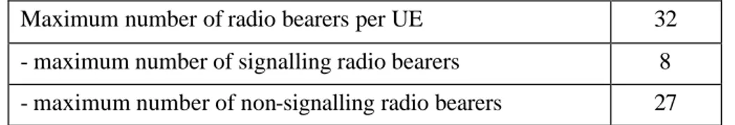
The maximum number of established radio bearer (signaling and non-signaling) between the UE and the RNC entity is shown in the following table 1 ([3G25331]).
Maximum number of radio bearers per UE 32
- maximum number of signalling radio bearers 8 - maximum number of non-signalling radio bearers 27
Table 1. A maximum number of established radio bearers between the UE and RNC entity.
Examples of radio bearer configurations at the UE side can be found in [3G34108]. Fur-thermore, this reference describes number of testing scenarios.
1.2.5 Transport channels for packet transfers
To carry packet data traffics over the radio interface, UMTS disposes of several different transport channels that can be applied. These channels can be divided into the three groups: (i) Random Access Channel (RACH, ↑), Forward Access Channel (FACH, ↓), and Common
Packet Channel (CPCH, ↑); (ii) dedicated channels (↑, ↓) (iii) shared channels (↓)
The first two channels of the first group, RACH and FACH, are appropriate for transmission of small data amounts, such as a single request of web-page ([HT00]). The CPCH is suitable for small and medium data amounts. In case of large data amounts, the first group of transport channels suffers from their poor radio performance and other channels should be employed ([HT00]). Contrary to RACH and FACH, CPCH is fast power controlled. None of these three channels supports soft handovers.
Channels in the second group, as the name indicates, are dedicated to the UE. Every user can have established several dedicated transport channels. These channels are suitable for me-dium and large data transfers. Dedicated channels supports fast power control and soft han
d-Chapter 1: Introduction of ARQ protocols in UMTS 9
overs. Since dedicated channels have to be set up at the beginning of transmissions (which takes certain time), the access time to them is longer than that of the channels in the first and third group.
To simplify our analysis concerning interactions between TCP and RLC protocol in chapter 4, these studies assume a TCP data transfer over the dedicated transport channel.
Shared channels dynamically share common radio resources among several users. The re-sources are assigned according to implemented packet scheduler; more about packet schedul-ing in UMTS can be found for example in [E03]. There are specified two shared transport channels. Both of them can transport as user data as signaling messages:
- Downlink Shared Channel (DSCH), introduced in Release 99 (1999), - High Speed DSCH (HS-DSCH), introduced in Release 5 (2002).
The DSCH channel supports fast power control and var iable spreading factor. The spreading factor of DSCH can vary from frame to frame, i.e. every 10 ms. To every UE, which uses DSCH, is assigned an associated dedicated downlink channel that carries relating DSCH in-formation (the transport format, power control, pilot bits, etc).
In a case of the HS-DSCH channel, the link adaptation is not provided through the fast power control and variab le spreading factor. Instead, the link adaptation is provided by con-tinuously adjusting Modulation and Coding Schemes (MCSs) according to current radio chan-nel conditions. The packet scheduling is moved from the RNC entity closer to the radio inter-face, i. e. to Node B. In addition, the allocation period is decreased from 10 ms to 2 ms (or three slot). Information about which UE(s) is scheduled in a given TTI (and as well other necessary information concerning HS-DSCH transmission) is transported through a downlink-signaling channel. We discuss more HSDPA signaling channels in section 5.2. A comparison of DSCH and HS -DSCH channels is provided in table 2.
Downlink Shared Ch (Release 99, 1999) High Speed Downlink Shared Ch (Release 5, 2002)
Variable spreading factor Yes No
Fast power control Yes No
Adaptive modulation and coding No Yes
HARQ No Yes
Transmission Time Interval (TTI) 10 ms 2 ms
Location of the packet scheduler RNC Node B
1.3 ARQ techniques in UMTS
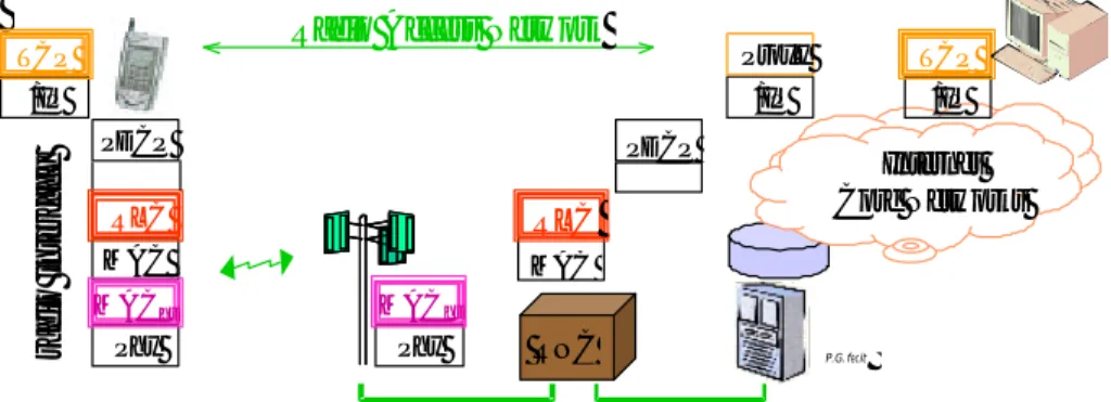
The UMTS system reinforces the radio link with more elaborated ARQ mechanisms co m-pared to 2G. The corresponding ARQ protocols can be found at the three different levels of the global UMTS protocol architecture: the 1st/2nd levels (physical/data link layers), the 2nd level (data link layer) and at the 4t h level (transport layer). The ARQ protocols operate between User Equipment (i.e. a mobile) and different network elements such as server (or proxy server), RNC entity and Node B.
TCP
The highest operating reliable mechanism is the ARQ of TCP at the transport layer. The ARQ of TCP (type Go-Back-N) ensures end-to-end reliable data transfers, i.e. between the mobile and server or proxy server. Proxy servers are widely used in nowadays Internet. These servers allow (fix, mobile) users to get remote web-pages locally from the proxy cache instead of downloading them from their original distant sites (for more about proxy see e.g., [RFC2616]).
Notice that since the introduction of the TCP protocol, features of links in wired networks have largely evolved. Due to the vast utilization of optic fibers in wired networks, wired links can presently be assumed to be reliable. The principal source of losses in these networks is overflows in routers (i.e. router congestions). The TCP behavior upon detecting congestions is discussed in chapter 3.
RLC
Reliable data transfers on the radio interface, i.e. between the UE and RNC entity, are real-ized through the RLC protocol; precisely through RLC entities that are configured to operate in an acknowledged mode (AM). Different aspects of AM RLC entities are investigated in chap-ter 2 and chapchap-ter 3.
MAC -hs
When updating the UMTS radio interface with the HSDPA mode, a hybrid ARQ mecha-nism is introduced at the physical and MAC-hs layers (1st/2nd levels). The HARQ of MAC-hs operates between the UE and the Node B. Being closer to the air interface the MAC-hs proto-col deals with erroneous data much faster than RLC does. The MAC-hs Round Trip Time (RTT) is about a dozen of ms contrary to several tens of ms in a case of RLC RTT. However, notice that the HSDPA mode was introduced for the downlink (HS-Downlink Packet Access). Therefore, contrary to the ARQ of RLC, the HARQ of MAC -hs is just applicable for downlink data transfers.
Chapter 1: Introduction of ARQ protocols in UMTS 11
The HARQ of MAC-hs is based on the simplest ARQ technique of type Stop&Wait (S&W). Several S&W instances (or process) can simultaneously be activated per a radio bearer. Due to the multi-instance ARQ together with a specific numbering, the HARQ of MAC-hs behaves as if a Selective Repeat method would be applied. We will analyze this feature in more details in section 5.2 where we study the HSDPA mode.
Figure 4. ARQ mechanisms in the global layer architecture of UMTS.
1.4 UMTS QoS Classes
Every UMTS service has specific requirements on wireless delay, bit error rate and eventu-ally data rate. These attributes are negotiated when establishing radio bearers.
UMTS services are group ed into the UMTS QoS classes or traffic classes according to their characteristics. Reference [3G23107] specifies four types of UMTS QoS classes (table 3): (i) conversational, (ii) streaming, (iii) interactive and (iv) background. The main distinguishable factor among these classes is how sensitive they are to delay.
Conversational and Streaming classes
The conversational class is the most delay sensitive UMTS QoS class. The most known ser-vice of this class is the voice. An insufficiently low end-to-end delay results in unacceptably quality from the user point of view. Since this class has strict requirements on the end-to-end delay, the ARQ mechanisms are not used; received data which delay exceeds a certain thres h-old is useless for the receiver, even tho ugh the data would be error free. Studies of the human perception shown that the end-to-end delay for voice services has to be less than 400 ms ([3G22105]). The RLC entity is configured to operate in Transparent Mode (we discuss this RLC mode in section 2.2.1). Furthermore, the data processing delay at the UMTS radio proto-col stack should be minimized as much as possible, i.e. TTI (Transmission Time Interval) is set to 10 ms. Phy MAC RLC Phy MAC PDCP /IP TCP PDCP /IP /IP RLC MAChs P.G. fecit radio interface Proxy TCP MAChs
Radio Access Network
Internet Core Networks
Contrary to the conversational class, the streaming class is less strict to the delay. The qual-ity of service is again determined by the human perception since the receiver is mostly a hu-man. The interactive class represents services such as audio or video streaming. These services usually employ buffering at the receiver’s side in order to smooth jitter of arrived data flows. This way, the reproduced flow is slightly put backed compare to the real time arrived flow. As shown in [M02], due to short MAC-hs RTT, the HARQ of MAC-hs with a restricted number of retransmission attempts is possible applied for streaming services. Compared to MAC-hs RTT, the RLC RTT is longer. The use of ARQ of RLC would introduce much more important radio delay than MAC-hs does. Therefore, the ARQ of RLC should be avoided for streaming services. We will return to streaming services when studying the HSDPA allocation mode (sec-tion 5.3).
Interactive and background classes
Interactive and background classes represent traditional Internet applications (e.g., web-browsing, telnet, etc.). Requirements on delay of these classes are looser than the previous ones. On the other hand, they require preserving data integrity. Therefore, radio bearers sup-porting these classes are configured to use either the ARQ of RLC or the HARQ of MAC-hs eventually both of them. The ARQ of RLC above the HARQ of MAC-hs could be used for ex-ample as “a safety against errors” that can pass through the MAC-hs layer.
Traffic class Conversational Streaming Interactive Background
Characteristics
Preserve time relation (variation) between information entities of the stream
Conversational pattern (stringent and low delay)
Preserve time relation (variation) between information entities of the stream Request response pattern Preserve data integrity Destination is not expecting data within a certain time
Preserve data integrity
Mode Circuit Circuit, Packet Packet Packet
ARQ MAC-hs MAC -hs, RLC
TCP
MAC -hs, RLC TCP
Example voice audio, video
streaming web-browsing SMS, MMS
Chapter 1: Introduction of ARQ protocols in UMTS 13
Interactive class corresponds to applic ations with the classical request response pattern such as web-browsing. In a case of web-browsing, the user expects a response in “reasonable” short time. The last class, background class, represents the less delay sensitive applic ations such as SMS (Short Message Service) or MMS (Multimedia Message Service). Since these applic a-tions do not require immediate action, they can run in background of other tasks that have higher priority. The delivery delay may range from few seconds up to few minutes.
1.5 Context and structure of the thesis
This thesis studies new features of the UMTS ARQ mechanisms and investigates possibili-ties of their enrichments. The accumulation of ARQ mechanisms at different levels of the UMTS global architecture goes with interactions between the ARQ protocols. Our work points some of TCP/RLC interactions and proposes a remedy to an adverse one.
A part of the thesis was realized in the framework of a RNRT project called MPRIM (Mod-ules PRotocolaires Interchangeables pour Mobiles multimedia, [Mprim]). The project was real-ized in cooperation of Alcatel, ENST, I2E, SFR and Thomson CSF Communications. The pro-ject has investigated a possibility of dynamic reconfigurations of the lower three layers of UMTS. Due to the high complexity of this issue, we have focused our interest on a parameter setting of the RLC layer; precisely on a parameter setting of a RLC entity operating in an ac-knowledged mode (AM).
1.5.1 Studied features and related works
Parameters such as RLC timers, the RLC transmission window or the maximum number of transmission attempts per RLC block are analyzed in [ZL02], [XC02a] and [LV01]. One of significant RLC parameters is also the RLC buffer size. Impact of different type of MAC scheduling algorithms (respectively different TCP receiving window sizes) on the RLC buffer size is analyzed in [MH03] (respectively in [LV01]). Our work investigates how different TCP protocol soft states affect the RLC buffer occupancy. The buffer occupancy by return affects the TCP RTT (Round Trip Time).
In context of TCP data transfers over the radio interface, two different cases have to be dis-tinguished: a TCP uplink and a TCP downlink transmission. In the first case, the RLC buffer (located in the UE) occupancy is determined by the operating system of UE and its internal flow control between RLC and TCP besides the TCP protocol soft states. The internal flow control is not standardized; its realization depends on the used operation system of UE. Our work considers the downlink case, where the internal flow between RLC and TCP control does not intervene and the RLC buffer (located in the RNC) occupancy is proportional to the TCP transmission window.
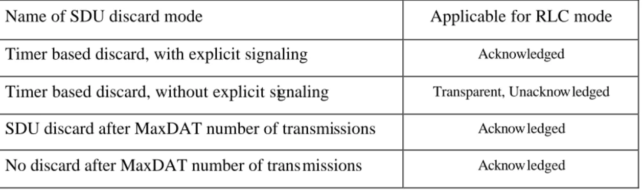
A classical problem of TCP on the radio interface represents the misinterpretation of wire-less and congestions losses. This problem is handled by different TCP extensions such as Indi-rect-TCP ([BB95]), Snoop ([BS96]), Wireless -TCP ([RM98]), etc. However, only a part of the TCP extensions for wireless networks consider a radio link with an ARQ protocol at layer 2. In UMTS, RLC avoids wireless losses due to its ARQ mechanism, unless a specific RLC function called SDU discard is active. The RLC SDU discard mechanism allows the AM RLC entity to delimitate a number of retransmission attempts per RLC blocks. High number of retransmis -sion attempts may result in TCP spurious timeouts. Two TCP exten-sions dea ling with TCP spurious timeouts are called Eifel ([LK00]) and EBSN (Explicit Bad State Notification, [BK96]). Neither Eifel nor EBSN covers the RLC SDU discard issue. We propose to consider the RLC SDU discard function and to introduce between RLC and TCP a specific mechanism called Early Error Notification (EEN). The EEN mechanism is proposed for TCP uplink transmissions and its use for downlink transfers is also discussed.
The HSDPA mode introduces a third hybrid ARQ mechanism at the phys ical and MAC-hs layers. Besides the HARQ mechanism, HSDPA brings several other features such fast schedul-ing or fast link adaptation through MCSs (Modulation Codschedul-ing Scheme). Majority of the HSDPA studies cover HSDPA link adaptation, performance of Error Correction Codes or HSDPA scheduling issues ([NA02], [DK02a], [KF02b]). HSDPA features make possible to it for stream ing services; the HSDPA performance for streaming services is analyzed in [M02]. Nevertheless, streaming services do not need such dynamic allocation that HSDPA offers. This type of services generates regularly outgoing data and such data flows postulate a periodic al-location. Our work discusses impact of periodic allocation on the dynamic allocation mode and on the HSDPA signaling.
For the time being, few studies concern MAC-hs protocol features; e.g. impact of MAC-hs window size on delay is studied in [MR03]. We approach this domain in two steps. In the first step, we propose to enrich the HSDPA link adaptation by modifying the MAC-hs PDU size during retransmissions attempts. In the second step, we study the effect of this enrichment on the HARQ process management and on the sp ecific MAC-hs numbering.
1.5.2 Structure of the thesis
Chapter 2
The next chapter is dedicated to the RLC protocol (Radio Link Control) of UMTS. Section 2.2 describes basic fact about RLC (RLC modes, type of RLC blocks, etc). The RLC QoS management is performed through a specific function called SDU discard that is explained in section 2.3.
Interlayer communication between RLC and its adjacent layers is investigated in section 2.4. In section 2.4.1, we briefly remind different types of interlayer primitives and their use.
Chapter 1: Introduction of ARQ protocols in UMTS 15
Section 2.4.2 (respectively section 2.4.3) details layer interface between RLC and the adjacent upper layer (respectively lower layer). The control interface between the RLC and RRC layers is analyzed in section 2.4.4.
Some differences between RLC of (E)GPRS and RLC of UMTS are mentioned in section 2.5. Chapter 2 terminates remarks concerning development and implementation of protocols (section 2.6).
Chapter 3
In chapter 3, we turn our attention to the transport layer and we study TCP (Transmission Control Protocol) in cellular networks with a focus on the UMTS radio interface. Section 3.2 remains some basic facts about TCP (protocol soft states, behavior when detecting a loss, etc.). Section 3.3 briefly presents other reliable transport protocol called Stream Control Transmis -sion Protocol. In section 3.4, protocol mechanisms of TCP are compared with the RLC ones. Section 3.5 analyzes the TCP behavior over RLC and we discuss usefulness of some proposed TCP extensions when used in the UMTS enviro nment.
Chapter 4
Chapter 4 studies protocol interactions between TCP and RLC (of UMTS). This chapter is decomposed into three parts. The first part briefly describes two mechanisms that in a restricted way allow informing the TCP transmitter about specific events occurring in the connection path; these are Internet Control Message Protocol (section 4.2.1) and Explicit Congestion Noti-fication (section 4.2.2).
The second part of chapter 4 (section 4.3) deals with the RLC buffer occupancy; we focus on TCP downlink transmissions. Section 4.3.1 describes our simulation environments. Section 4.3.2 investigates two of factors that influence the RLC buffer occupancy: (i) wired Round Trip Time (RTTwired) and (ii) Block Error Rate (BlER) on the radio interface. In addition, impact of
different RLC buffer sizes on the TCP performance is analyzed. The RLC buffer investigations are concluded in section 4.3.3.
The third part of chapter 4 (section 4.4) discusses a mechanism EEN (Early Error Notific a-tion) that we propose to introduce between TCP and RLC. Section 4.4.1 details the proposed mechanism for a TCP uplink data transmission. The simulation experiments and results are de-scribed in section 4.4.2. Contrary to the uplink case, in the downlink case a TCP transmitting entity and a RLC entity are each located in different equipments. Thus, EEN cannot be directly applied in downlink as described in section 4.4.1. A possibility of using EEN for downlink transmission is discussed in section 4.4.3. The EEN studies are concluded in section 4.4.4.
Chapter 5
Chapter 5 covers the HSDPA mode (High Speed Downlink Packet Access) for UMTS. Sec-tion 5.2 describes the HSDPA context (new channels, layer structure, protocol mechanisms, etc).
Section 5.3 is dedicat ed to the HSDPA allocation mode. Basic facts about the dynamic allo-cation mode are provided in section 5.3.1. The periodic alloallo-cation and its features are described in section 5.3.2. Simulation experiments concerning the dynamic and periodic allocation are depicted in section 5.3.3. Section 5.3.4 concludes studies about the allocation of radio re-sources in HSDPA.
The last part of chapter 5 (section 5.4) discusses the HSDPA link adaptation procedure and a possible enrichment of this procedure. The standard HSDPA link adaptation procedure is de-scribed in section 5.4.1. Section 5.4.2 provides more details about the enrichment that we pro-pose introduce in the link adaptation procedure and we study its impact on Phy/MAC-hs layer. Section 5.4.3 depicts simulation environment and parameter setting. Performance of the stan-dard and proposed adaptation schemes is compared in section 5.4.4. The HSDPA link adapta-tion analyses are concluded in secadapta-tion 5.4.5.
Chapter 6
In chapter 6, we provide main conclusions and we outline some possible future research di-rections.
17
Chapter 2
Radio Link Control
2.1 Introduction
Several substantial differences can be observed between wired and cellular networks. Cellu-lar networks generally dispose of a lower bandwidth for transmission (meaning also lower rates) than wired networks do. In comparison with wired networks, cellular networks have to deal with user mobility, i.e. handoffs. Furthermore, the air represents a medium with high vari-ability (fading, interferences, etc.). The varivari-ability of medium and the user mobility results in bit error rates that are much important in cellular networks (as high as 10-3) than in wired net-works (less than 10-7). In order to detect and rapidly deal with errors on an air interface, the ra-dio protocol stack of cellular systems implement reliable techniques. The next section reminds the basic reliable mechanisms and provides an overview of data link protocols.
2.1.1 Reliable mechanisms
There are two principal reliable techniques: ARQ (Automatic Repeat reQuest) and FEC (Forward Error Correction). The first reliable technique (ARQ) handles errors by re-transmitting data according to receiver demands, whereas the FEC technique makes use of Er-ror Correction Code (ECC) that allows the receiver to detect and correct the erEr-rors. The FEC receiver is capable to detect and correct a data unit that contains fewer than a predetermined number of errors in the unit. Our studies focus on the ARQ technique. More about ECC can be found in [CD92].
ARQ technique
Compared to FEC, the ARQ technique requires one bi-d irectional connection between the transmitter and the receiver. One direction is reserved for data transmission from the transmit-ter to the receiver. The opposite direction is used by the receiver to transfer status reports, i.e. Ack/NAck (positive/Negative Acknowledgement). Through status reports, the receiver informs the transmitter about data (blocks) that has to be retransmitted. To unambiguously distinguish blocks, the ARQ protocol has to effectuate their numbering. A block is retransmitted until the
block is either correctly received or a predetermined number of retransmissions is reached re-spectively a specific timer delimitating the maximum retransmission period expires. The ARQ protocol can manage either just one block (Stop and Wait) or several blocks at a time (Go-Back-N, Selective Repeat). Notice that erroneous data at the receiver side is thrown away; the receiver does not store it in its receiver buffer.
HARQ technique
By combining the ARQ and FEC techniques, we obtain a third technique called hybrid ARQ (HARQ). The ARQ part of HARQ can be provided by any of the earlier mentioned ARQ mechanisms (Stop and Wait, Go-Back-N, Selective Repeat). Compared to the ARQ receiver, the HARQ receiver may store received erro neous data to combine it with data that is received in the follo wing retransmission attempts. There have been specified several HARQ schemes (HARQ-I, HARQ-II, etc.); more about them can be found for example in [M74], [LC84], or [DK02b]. In our work, we are just interested about the HARQ mechanism from the view of its protocol mechanisms, i.e. about the ARQ part of HARQ.
2.1.2 Overview of data link protocols providing reliable transfers
One of the best-known data link protocols for reliable transfers is the HDLC (High -Level Data Link Control) protocol. As a matter of fact, many other data link layer protocols are based on it; for example LAPB (Link Access Protocol Balanced) for X.25, LAPD (Link Access Pro-tocol in the D channel) for ISDN (Integrated Services Digital Network), LAPM (Link Access Protocol for Modems) for V.42 modem, etc.
The data link layer of GSM includes a protocol called Radio Link Protocol (RLP). The RLP protocol is based on a simple protocol of type LAPDm (Link Access Protocol on the Dm chan-nel), which is a modified version of LAPD. Notice that the cdma2000 system also specifies at the data link layer the RLP protocol (RLP-cdma2000), which however differs from the GSM version. From others reliable data link protocols, we may mention Service-Specific Connection Oriented Protocol (SSCOP) of ATM (Asynchronous Transfer Mode) or Error Control (EC) protocol that is utilized in HiperLAN/2.
In the next study, we restrict our view on the GSM/GPRS and UMTS environments and on a data link protocol of type RLC (Radio Link Control). A first simple version of RLC was in-troduced in the GPRS system (see e.g., [LG99]). The RLC version of GPRS operates between a mobile and BSS (Base Station Sub -system). The protocol provides either a reliable or an un-reliable tran sfer of LLC messages (Logical Link Control) over the GPRS radio interface.
A more advance version of the RLC protocol has been introduced in the UMTS system. In comparison with RLC of GPRS, RLC of UMTS is more elaborated and offers more services to
Chapter 2: Radio Link Control 19
the upper layer. This chapter provides more details about protocol mechanisms. There will ex-plicitly be mentioned when considering a RLC version of different cellular systems.
This chapter is organized as follows. The next section discusses basic facts about the proto-col (protoproto-col modes, protoproto-col units, etc.). Section 2.3 describes a specific RLC function called SDU discard. Inte rlayer communication between RLC and the upper and lower adjacent layers is studied in section 2.4; there is also detailed the control interface between RLC and RRC. Some of major differences between RLC of (E)GPRS and RLC of UMTS are provided in sec-tion 2.5. Chapter 2 is concluded by remarks concerning development and implementasec-tion of protocols (section 2.6).
2.2 Basic fact about RLC of UMTS
The RLC protocol operates between the UE (User Equipment, or mobile) and RNC entities (Radio Network Controller). The eponymous RLC layer can be seen as a composition of sev-eral RLC entities or RLC instances that operate independently. An establis hment, (re)configuration and release of a RLC entity are controlled by the upper layer RRC (R adio Resource Control). There are established as many RLC entities per UE as many radio bearers are established between the UE and RNC entities.
One of RLC tasks is to segment upper layer protocol units, i.e. RLC SDUs (Service Data Unit), into RLC protocol units (RLC Blocks) that are more suitable for transmissions over the radio interface. A RLC SDU is shortly denoted as a SDU in the rest of the thesis. A SDU can contain either user data (when delivering from the user plane) or signaling messages (when de-livering from the control plane). There is no implementation difference between RLC entities that handle user data and entities that handle signaling messages.
2.2.1 RLC Modes
Compared to RLC of GPRS, a RLC entity of UMTS can be configured to operate in one of the following three modes:
(i) Transparent Mode (or TM), (ii) Unacknowledged Mode (or UM), (iii) Acknowledged Mode (or AM).
Transparent mode
This mode is the simplest mode. A TM RLC entity does not add any RLC protocol overhead to an upper layer unit (i.e. a SDU). The entity is transparent to SDUs. This type of RLC mode is used for a service that tolerate higher bit error rate; however the end-to-end delay has to be
kept low. Such type of service is for example voice, where the maximum end-to-end delay is determined by the human perception.
Unacknowledged mode
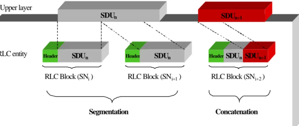
Likewise a TM RLC entity, a UM RLC entity does not guarantee correct deliveries of RLC blocks to the peer entity. Contrary to a TM entity, an UM entity adds RLC overheads to data. The header of UM RLC block consists of one byte: Sequence Number (SN, 7 bits) and Exten-sion bit (E, for more see the acknowledged mode). Since RLC blocks are numbered, an UM entity can provide segmentation of SDUs and their reassembling at the receiver side. If possi-ble, the entity applies a concatenation, i.e. a RLC block can contain fragments of 2 SDUs. An example of the segmentation and concatenation of SDUs is illustrated in figure 5.
If a receiving UM entity detects a missing RLC block, the entity automatically discards all RLC blocks that are part of the same SDU(s); a missing block is detected by reception of a block with SN that is out of order. By this way, reassembled SDUs are always delivered to the upper layer in order (some of SDUs can be missing). The unacknowledged mode is utilized for transfers of cell broadcast messages or for transfers of certain RRC messages.
Figure 5. An example of segmentation and conca tenation of RLC SDUs.
Acknowledged mode
This last mode is the most elaborated RLC mode. A RLC entity is configured to operate in AM if a reliable data transfer over the UMTS radio interface is required. The RLC protocol uses the ARQ technique of type Selective Repeat.
Compared to a UM RLC entity, an AM RLC entity can be configured to deliver reassem-bled SDUs to the upper layer either in sequence or out of sequence (i.e. a SDU is delivered to the upper layer as soon as is reassembled). When using TCP at the transport layer, changes of
RLC entity Upper layer Header SDUn RLC Block (SNi ) SDUn SDUn+1 Header SDUn RLC Block (SNi+1 ) HeaderSDUn RLC Block (SNi+2 ) SDUn+1 Segmentation Concatenation
Chapter 2: Radio Link Control 21
SDUs order at the RLC level may result in the degradation of TCP performance; this is due to the TCP behavior on reordered segments (for more see section 3.2). Thus, if an AM RLC entity handles TCP segments, the entity has to d eliver SDUs to the upper layer in-sequence.
An AM entity is utilized for services that tolerate higher wireless delays and require pre-serving data integrity (e.g., file tran sfer).
A TM or UM entity is unidirectional. This means that for a bi-directional connection (unre-liable), two peer RLC entities need to be established; one peer controls transmission from the UE to RNC entity and the second peer controls transmission from the RNC to UE entity. An AM entity is bi-directional; one combined entity controls as transmission as reception.
2.2.2 Types of RLC blocks and their structures
There are two types of RLC blocks: (i) PDU (denoted as Data PDU in the rest of the thesis) and (ii) Status PDU. TM and UM RLC entities just manage Data PDUs.
Data and Status PDUs
A Data PDU can contain data or RRC signaling message(s), whereas a Status PDU carries RLC related control information. RLC control information can be intended either to the sender or to the receiver, i.e. as the sender as the receiver can transmit a Status PDU.
A Status PDU is composed of one or several fields called Super Fields or SuFi (figure 6). For example, a super field called ACK carries, as the name indicates, an acknowledgement. There are specified 8 types of SuFis (table 4). Some of them have a var iable size that may change from Status PDU to Status PDU, whereas other SuFis have a fix size. The utilization of each SuFi will be presented through chapters 2 and 3.
Name of Super Field (SuFi) Transmitted by Size [bits]
NO_MORE (No More Data) Sender or
receiver 4
WINDOW (Window Size) Receiver 16
ACK (Acknowledgment) Receiver 16
BITMAP (Bitmap) Receiver 28…148*
LIST (List) Receiver 24…264*
RLIST (Relative List) Receiver 24…80*
MRW (Move Receiving Window) Sender 24…192*
MRW_ACK (Move Receiving Window Acknowledgement) Receiver 20
The end of the super field part (i.e. the end of useful information) in a Status PDU is delim-ited by super fields ACK or NO_MORE. Bits following these SuFi are considered to be pad-ding bits (Pad) and are ignored by the RLC receiver.
If an AM entity is connected to the MAC layer via one logical channel, the same size of Data PDUs and Status PDUs has to be used. A Status PDU carries in most cases a few bytes of useful information compared to a Data PDU (≈ 128, …, 640 bits, [3G34108]). To reduce the amount of useless padding bits that are transferred over the radio interface, an AM entity can be co nnected to the MAC layer through two logical channels. One logical channel transports Data PDUs, whereas the second channel transports Status PDUs. Thus, the Data PDU and the Status PDU can have a different size.
Figure 6. Structure of a Status PDU.
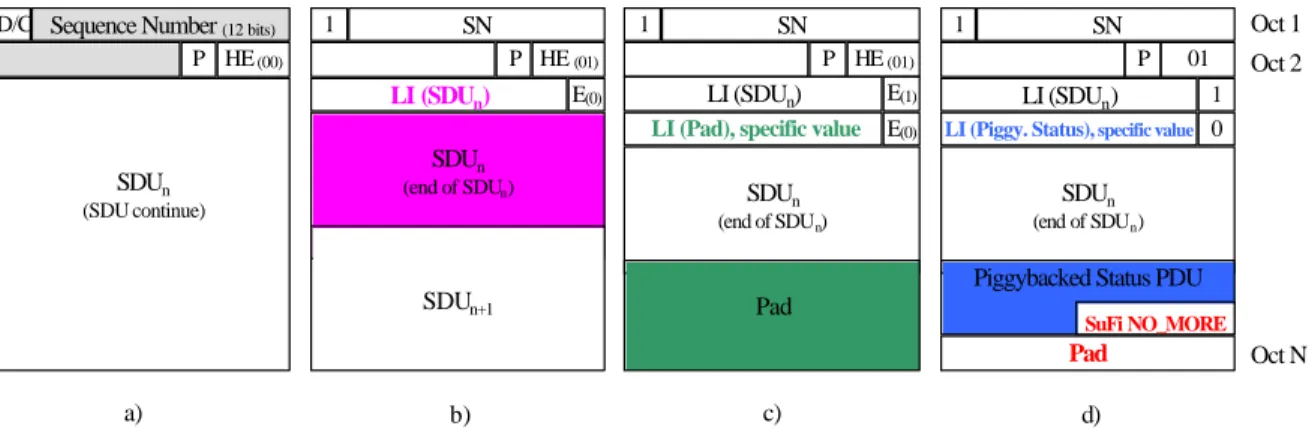
In a case of AM RLC entity, one RLC block can contain as data as RLC control inform a-tion. As it well known, the technique, where data and control information are sent in the same protocol unit, is called piggybacking. The piggybacking control information form a RLC block called, in the RLC specification ([3G25322]), Piggybacked Status PDU.
Notwithstanding, the utilization of the RLC piggybacking mechanism is restricted. The mechanism can only be applied if a Data PDU contains the end of a SDU and the RLC entity would apply either padding or concatenation. If RLC control information cannot be postponed until the end of a SDU or if there is not enough space to insert the whole Piggybacked Status PDU into the Data PDU, a stan dalone Status PDU has to be employed.
Structure of Data PDU
Figure 7 shows an example of possible structures of Data PDUs that are managed by an AM entity. The first two bytes constitute the RLC header of a (AM) Data PDU. The first bit of the header, called D/C (Data/Control), specifies the type of PDU (Data/Status). The Polling bit (P) is used by the sender to demand the receiver to send a status report (i.e. Ack/NAck). More about the RLC acknowledgment policy provides section 3.3. The Header Extension (HE) flag indicates the meaning of the fo llowing byte, i.e. data or flags LI and E (see next).
SuFi SuFi 0 0 0
0
Sufi ACK or NO_MORE Pad (if necessary)
:
Oct 1
![Figure 1. Network components of UMTS architecture ([ST01]).](https://thumb-eu.123doks.com/thumbv2/123doknet/2971544.82588/20.918.187.745.685.1006/figure-network-components-umts-architecture-st.webp)
![Figure 2. The UMTS radio protocol stack in a UE resp ectively in an RNC entity ([HT00])](https://thumb-eu.123doks.com/thumbv2/123doknet/2971544.82588/21.918.255.683.679.993/figure-umts-radio-protocol-stack-resp-ectively-entity.webp)
![Table 2. A comparison of features of DSCH and HS-DSCH (inspired by [H02]).](https://thumb-eu.123doks.com/thumbv2/123doknet/2971544.82588/26.918.177.744.795.1031/table-comparison-features-dsch-hs-dsch-inspired-h.webp)
![Table 3. UMTS QoS classes (inspired by [3G23107]).](https://thumb-eu.123doks.com/thumbv2/123doknet/2971544.82588/29.918.142.784.675.1008/table-umts-qos-classes-inspired-g.webp)