HAL Id: hal-01008948
https://hal.archives-ouvertes.fr/hal-01008948
Submitted on 6 Jan 2020
HAL is a multi-disciplinary open access archive for the deposit and dissemination of sci-entific research documents, whether they are pub-lished or not. The documents may come from teaching and research institutions in France or abroad, or from public or private research centers.
L’archive ouverte pluridisciplinaire HAL, est destinée au dépôt et à la diffusion de documents scientifiques de niveau recherche, publiés ou non, émanant des établissements d’enseignement et de recherche français ou étrangers, des laboratoires publics ou privés.
Combining NDT tools for analysing the efficiency of
repair techniques of wharves: the MAREO project
Farouk Benmedour, Géraldine Villain, Xavier Dérobert, Odile Abraham,
Franck Schoefs, Marianne Perrin, Stéphanie Bonnet, Marta Choinska
To cite this version:
Farouk Benmedour, Géraldine Villain, Xavier Dérobert, Odile Abraham, Franck Schoefs, et al.. Com-bining NDT tools for analysing the efficiency of repair techniques of wharves: the MAREO project. 11th International Conference on Applications of Statistics and Probability in Civil Engineering, (ICASP’11), 2011, Zurich, Switzerland. �hal-01008948�
COMBINING NDT TOOLS FOR ANALYSING THE EFFICIENCY
OF REPAIR TECHNIQUES OF WHARVES: THE MAREO PROJECT
Farouk BENMEDDOUR1, Géraldine VILLAIN1, Franck SCHOEFS2, Marianne PERRIN2, Xavier DÉROBERT1, Stéphanie BONNET2, Odile ABRAHAM1, Marta CHOINSKA2.
1
Laboratoire Central des Ponts et Chaussées, LCPC, centre de Nantes, Route de Bouaye, BP 4129, 44341 Bouguenais, France.
2
Nantes Atlantique University, Institut de recherche en Génie civil et Mécanique (GeM), CNRS UMR 8163, 2 rue de la Houssinière, BP 92208, 44322 Nantes, France.
Farouk_Benmeddour@yahoo.fr Geraldine.Villain@lcpc.fr
KEYWORDS: Destructive Testing, Non-Destructive Testing, Ultrasonics, Chloride, Repair.
ABSTRACT
Repair of structures in concrete is still a challenge, especially when access and environment offer a difficult context such as the case of wharves. Concerning the repair of concrete for marine structures, European standards give the requirements in predefined and standardised conditions. However, repair of wharves is performed in harsh conditions such as access, humidity and operator position. These conditions do not enable the direct application of standards. By accounting for these requirements, the repair technique consists in rebuilding the concrete cover and in some cases using protective coating for some beams. In this paper, we focus on the concrete repair techniques. The aim of MAREO project (French project of the National competitive cluster in Civil Engineering and Eco-Building) is to compare several repair techniques carried out in the most complex area for repair: the tidal zone. The project deals with initial performance, sustainability, cost of durability and concrete properties monitoring by destructive testing (DT) and non destructive testing (NDT) techniques. The studied NDT techniques are: impact-echo, surface waves, multi-offset radar, and capacitive method. Both, beams placed in natural exposure and slabs specimens placed in accelerated conditions in laboratory are considered. For all the beams, the contaminated concrete was removed using high-velocity water jets (hydro-demolition). The selected techniques are wet shotcrete, dry shotcrete, formed concrete and manual repair. This paper focuses on the ability of NDT techniques to evaluate the changes of properties related to the chloride ingress in concrete both on site and in laboratory accelerated conditions. The interest of each technique and its sensitivity to several physical factors are highlighted. The need of NDT-combination is illustrated.
I. INTRODUCTION
564 various types of ports can be found along the French coastline, 60% of which were built before 1955. Furthermore, environmental considerations have raised important questions regarding the new developments and decommissioning of existing infrastructure. The maintenance planning optimisation is therefore a major challenge with multiple constraints imposed by tourism, economical and environmental considerations. Infrastructure managers have to optimise actions even if the choice of multiple technical solutions is complex. This is due to the lack of accurate and reliable knowledge on the performance of these techniques and their evolution with time. Based on these considerations, the MAREO project was developed with two objectives. The first one is to compare the efficiency of repairing techniques on concrete structures in coastal regions within the global context of reassessment of repaired structures. The project therefore relies on global methodologies for risk analysis and assessment. The second one is to identify and quantify uncertainties and hazard sources in assessing the performance functions.
The project research work was performed at several levels. Firstly, identify the performance indicators of structures. Secondly, investigate exhaustively the evaluation chains of these indicators and compare them in terms of risk analysis. This implies particularly to consider modelling uncertainties and to propose other models based on non-deterministic approaches (for example probabilistic: physical or analytical response surfaces) and to identify uncertainties on performance indicators or influential factors and thereby to characterize the so-called intrinsic hazards. Thirdly, outline experimental devices and protocols, in laboratory or on site (pilot building sites), with controlled conditions of measurement; identify failure mechanisms. Then, suggest computational methods from previous works for re-engineering. Develop a methodology for semi-probabilistic analysis through pilot studies (20 x 80 years old beams repaired and tested, repaired structures from harbours (PANSN) and general council (CG44), repaired beam with composite sticking).
The paper focuses on the developments around the use of non-destructive testing (NDT) techniques and destructive testing (DT). Beams placed in natural exposure and slabs specimens in accelerated conditions in laboratory are considered. For all the beams, the contaminated concrete was removed using high-velocity water jets (hydro-demolition). The selected repair techniques were wet shotcrete, dry shotcrete, formed concrete and manual repair. This paper focuses on the ability of the NDT techniques to evaluate the changes of properties related to the chloride ingress in concrete both on site and on specimens in laboratory. The interest of each technique and its sensitivity to several physical factors are highlighted. The need of the combination of different NDT techniques is illustrated.
Section II of the paper is devoted to the presentation of the experimental procedure. Beams and slabs were presented in addition of reparation techniques. Then, the destructive and non-destructive testing techniques were explained. Section III deals with obtained results with different methods. Results are then analysed by statistical methods which lead to discussions then conclusions.
II. EXPERIMENTAL PROCEDURE
A. Materials and specimens description
1. Beams
In this work four beams of 200x34 cm2 and 75 cm of height are considered. These beams arise from the demolition in 2006 of a wharf made of reinforced concrete at the Lorient port in the west of France. Then, the contaminated area by chlorides has been removed by hydro-demolition and beams were repaired in September 2008. Three different industrial ready-to-mix concretes were used to repair the beams with four different techniques. The reparation techniques are: (I) wet shotcrete, (II) dry shotcrete, (III) manual repair and (IV) formed concrete. The reparation mixings (I) and (III) contain the same industrial cement. After reparations, all surfaces were form worked for minimising the roughness. Frames were identified in the beams by using radar method. Based on these frames, four meshes were chosen on the horizontal surface of each beam (e.g see Figure 1).
≈ 200 cm Electrical electrodes M1 M2 M3 M4 ≈ 40 cm 22 cm 34 cm
Figure 1 Upper view from the central part of the beams
The first destructive and non-destructive tests were made in November 2008 and indicated by time 0 (t0). Then, the beams were installed in the tidal basin. Natural cycles of tidal range began on January 12,
2009. After 8 months (36 weeks, 252 days) of tidal range, second tests (time 1 or t1) were made on
September 2009. Beams were returned to enable non-destructive tests on the repaired surface which was submitted to the tidal range.
2. Slabs
Ten slabs were fabricated during the repair of beams with the same materials and the same techniques as numbered before. The dimensions of these slabs except one are 45x45 cm2 and 12 cm of height. Six slabs, numbered from 1 to 6, were designed first to the non-destructive tests then, to the destructive ones. However, only the 5th and the 6th slabs were studied in this paper. The 7th slab was conserved in the basin of unsalted water as a reference for the non-destructive tests. Slabs 8 and 9 will not be analysed in this work. Slab 10 has the dimensions 50x50 cm2 and 25 cm of height. This slab was cored for the initial characterisation with destructive tests.
The first destructive and non-destructive tests on the 5th, 6th and 7th slabs were realised in November 2008 (t0). Then, the 5th and 6th slabs were installed in the tidal basin. Accelerated cycles of
tidal range began on April 2009. After 1.5 month (6.14 weeks, 43 days) of tidal range, second tests (t1) on
slabs 5 and 6 were made on July 2009.
B. Destructive Testing techniques
Results of the destructive tests (DT) can be used as inputs or outputs of actual models of the prediction of structures life-time in reinforced concretes. Therefore, on one hand, they allow the characterisation of different repair materials and the studied implementation techniques and on the other hand, they serve as reference methods to compare to the NDT methods. The DT measurement techniques used in this work are proven, standardised or during normalisation.
1. Mechanical characteristics and durability indicators
The mechanical characteristics were determined experimentally. The measurement protocols of measuring the compressive strength Rc, the static Young’s modulus Estat and the coefficient of Poisson ν
were conforming to the European standards NF EN 206-1, 2004 and NF EN 13412, 2006. Measurements were curried out on cylindrical cored samples of the 10th slab. Three cored cylinders per material have a length to diameter ratio equal to 2. Three samples were used to determine Rc, Two to determine Estat and
only one to determine ν [Perrin, 2010].
Concerning the durability indicators, the global porosity accessible to water φ and the dry density of concretes ρdry were determined with respect to the recommendations of AFPC-AFREM, 1997 and
Arliguie, 2007. Three cored cylinders were used to determine the aforementioned modulus by vacuum water saturation.
2. Profiles of chloride determination
After each accelerated cycle of tidal range, slabs were cored. Due to the result dependence to the material homogeneity, three samples were cored for each slab. Samples of 12 cm of height and 9.5 of diameter were cored with successive grinding steps of 0.3 cm to obtain the powder to be analysed at different depths [AFPC-AFREM, 1997]. The free and total chloride levels were measured and expressed in grams per 100 grams of concrete. Chloride levels can be compared to the chloride threshold of 0.064 g per 100 g of concrete. Beyond this threshold, corrosions can be developed in concretes containing steel reinforcements or metal in tidal zones [NF EN 206-1, 2004].
C. Non-Destructive Testing techniques
1. Introduction
The NDT techniques are not commonly used for the diagnostics of structure performances. However, NDT methods are well correlated with durability indicators and provide valuable information for diagnosis on porosity, mechanical properties and water content of reinforced concrete structures. Furthermore, it is particularly interesting to combine non-destructive methods [Villain, 2009a].
2. Impact-echo method
The impact-echo method consists in the measurement of a resonance frequency. This is obtained by the Fourier transform of the received temporal signal on the beam or the slab. The temporal signal is excited by the chock of a steel ball on the surface of the sample at the centre. For an infinite sample like-beam the resonance frequency corresponds to the first symmetric (S1) mode of the guided Lamb waves.
By using this frequency, the Young’s modulus can be determined [Gibson, 2005]. However, in the case of slabs, different resonance frequencies were obtained. These frequencies correspond to the vibration modes of a cube which can be predicted with numerical methods. Then, the Young’s modulus and the Poisson coefficients can be obtained by using an inversion algorithm [Villain, 2009b].
3. Surface waves method
The surface waves can propagate over the surface of the sample and currying out significant energy. These waves are sensitive to the concrete characteristics over a depth corresponding to the wavelength. The phase velocity dispersion curves are then obtained. By using an inversion algorithm [Chekroun, 2009], some characteristics of the concrete can be obtained. Surface waves were generated with a piezo-electric transducer at the central frequency 120 kHz. Propagated waves are then acquired with a laser interferometer at different distances on a line of 38 cm with a step of 0.5 cm [Abraham, 2009]. For this work the wavelength of the surface waves was chosen to be 3 cm to enables comparison with other techniques.
4. Multi-offset radar method (CMP)
The radar technique is based on the generation and reception of a radar impulse through a beam or a slab. The velocity of the electromagnetic direct wave can be derived from the measurement of the flight time by using a calibration process [Dérobert, 2008, Villain, 2009a]. Hence, the relative permittivity of the tested material can be computed. In this paper, modified radar using bi-static antennae was used which enables different offsets between the emitter and the receiver. The central frequency of the antennae is 1.5 GHz and for practical reasons, only four offsets were investigated which is compatible with inspections on civil engineering structures. Measurements were realised at the centre of meshes and slabs to minimise edge effects.
5. Capacitive method
The capacitive method uses two electrodes and an oscillator circuit. In fact, the electrodes are applied on the surface of the sample which represents a condenser. Then, by combining this condenser with resistance and an inductor, a tuned circuit is obtained (RLC). Hence, the resonance frequency of this circuit depends on the geometry of electrodes and the relative permittivity of the sample [Dérobert, 2008]. The oscillator circuit has a resonant frequency in the range [30 ; 35] MHz. This frequency varies with function of dielectric nature of concrete which is related to the moisture, the nature of aggregates and the water to cement ratio.
Three different electrodes were used for experiments. The first is constituted of 5 electrodes with the combination: 2 and 3 linked electrodes and called small electrodes (SE). Each electrode has the dimensions 0.5x7 cm and the distance between two adjacent electrodes is 0.5 cm. The second is
constituted of 4 electrodes (2x2) and named middle electrode (ME). Each electrode has the dimensions 1x7 cm and 1 cm between them. The last one has 2 electrodes (1x1) with the dimensions 4x7 cm and 4 cm between them and called great electrode (GE). The depths of investigation of SE, ME and GE are 0.2 to 0.3 cm, 1 to 2 cm and 7 to 8 cm, respectively.
III. RESULTS AND DISCUSSIONS
A. Destructive Testing techniques
1. Mechanical characteristics and durability indicators
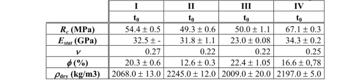
The measured results of Rc, Estat, ν, φ and ρdry are shown on Table 1. Comparing the porosity
accessible to water in each indicative class of durability for concretes, given by the AFGC Guide [Baroghel, 2004], we obtain a medium potential of durability for the dry shotcrete and a very low one for the other materials as shown in [Perrin, 2010]. However, the indicative classes of durability were estimated from measures on laboratory concretes kept 90 days underwater. Thus, the procedure was not respected in this work. In fact, the slabs were stored in open air after 24 hours minimum of wet curing then, they were removed from the mould. This procedure is more representative of the real conditions of construction. Due to this, a higher porosity was obtained.
Table 1: Results of the mechanical and micro-structural characteristics of reparation concrete
I II III IV t0 t0 t0 t0 Rc (MPa) 54.4 ± 0.5 49.3 ± 0.6 50.0 ± 1.1 67.1 ± 0.3 Estat (GPa) 32.5 ± - 31.8 ± 1.1 23.0 ± 0.08 34.3 ± 0.2 ν 0.27 0.22 0.22 0.25 φ (%) 20.3 ± 0.6 12.6 ± 0.3 22.4 ± 1.05 16.6 ± 0,78 ρdry (kg/m3) 2068.0 ± 13.0 2245.0 ± 12.0 2009.0 ± 20.0 2197.0 ± 5.0
2. Profiles of chloride results
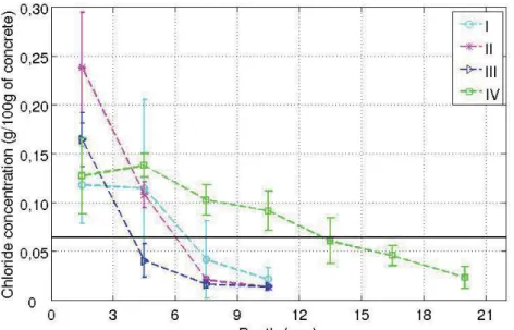
Figure 2 depicts profiles of totals' chloride and error bars measured on three cored samples from each slab (5) and each concrete of reparation. The line (0,064%) on this figure designates the threshold of corrosion. It can be shown that the chloride concentration of the formed concrete (IV) reaches the corrosion threshold between 1.2 and 1.5 cm of depth. However, concretes I, II and III reach the aforementioned threshold between 0.3 and 0.9 cm of depth. Although the wet shotcrete (I) is more porous than the dry shotcrete (II), the chloride concentrations have the same order of magnitude except between 0 and 0.3 cm of depth. Notice that the threshold indicated by the European standard [NF EN 206-1, 2004] was 0.4 % with respect to the mass of cement. In this work, the used threshold was recomputed with respect to the mass of the concrete by supposing cement content of 350 kg/m3.
Figure 2: Chloride concentrations measured on slabs of wet shotcrete (I), dry shotcrete (II), manual repair (III) and formed concrete (IV) at t1 after 43 days of accelerated tests.
B. Non-Destructive Testing techniques
1. Impact-Echo results
The mean of the measured frequency of the first symmetrical Lamb mode (fS1), the standard
deviation (STD) and the coefficients of variance (CoV) are shown on Table 2. It is observed that frequencies of S1 mode increase with time in the case of concretes II, III and IV. This can be explained by
the increase of the Young’s modulus due to ageing slabs and or to a higher saturation level.
Table 2: Results of the impact-echo method.
I II III IV t0 t1 t0 t1 t0 t0 t0 t1 mean fS1 (Hz) 2440 2391 2489 2587 2391 2538 2684 2733 STD 169 56 126 98 126 178 56 0 Beams CoV 7 2 5 4 5 7 2 0 mean fS1 (Hz) 15943 16349 17130 17326 16008 16349 16854 17716 STD 692 1035 345 69 258 207 56 69 Slabs CoV 4 6 2 0 2 1 0 0
The inversion process of the aforementioned results leads to the Young’s moduli and the coefficients of Poisson (Table 3). These results are dispersive due to the fabrication process of concretes which was in real conditions and on site. It is shown that Young’s moduli of slabs are greater than those of beams. This may be explained by a lower strength of an oldest concrete of the beam’s heart. It also observed that the dry shotcrete (II) has the greatest dynamic Young’s modului. In addition, Young’s dynamic moduli are greater than static ones.
Table 3: Young’s moduli and the coefficients of Poisson.
I II III IV t0 t1 t0 t1 t0 t0 t0 t1 Edyn± 2 (GPa) 31.2 29.0 30.1 32.6 31.0 31.2 38.0 39.5 Beams ν ± 0.02 0.25 0.25 0.25 0.25 0.25 0.25 0.25 0.23 Edyn± 2 (GPa) 35.6 35.0 43.4 47.0 35.7 37.2 39.2 39.8 Slabs ν ± 0.02 0.25 0.26 0.26 0.26 0.27 0.25 0.23 0.23
2. Phase velocities measurements of surface waves
Table 4 presents means of the measured phase velocities (Vϕ(λ=3cm)) on beams and slabs, their
standard deviations and variance coefficients at t0 and t1 of the studied reparation concretes. The measured
phase velocities of surface waves are generally similar except for the concrete II which is slightly higher. Insignificant increasing of the phase velocities between t0 and t1 was observed.
Table 4: Means, standard deviations and coefficients of variance of surface phase velocities.
I II III IV t0 t1 t0 t1 t0 t0 t0 t1 Mean Vϕ(λ=3cm) (m/s) 2431 2445 2435 2433 2277 2398 2292 2374 STD 202 71 27 110 63 79 35 11 Beams CoV 8 3 1 5 3 3 2 0 Mean Vϕ(λ=3cm) (m/s) 2251 2317 2368 2445 2387 2364 2126 2336 STD 69 23 93 13 142 7 181 23 Slabs CoV 3 1 4 1 6 0 9 1
3. Multi-offset radar method (CMP)
Table 5 shows means of the measured permittivity (εr'), the standard deviations and the
coefficients of variance at times t0 and t1 of different concretes. Results show an increasing of the
permitivity between t0 and t1. This change can be interpreted as an average increase of water content in
the slabs.
Table 5: Results of the GPR with multi-offset bi-static antennae.
I II III IV t0 t1 t0 t1 t0 t0 t0 t1 εr' mean - 8.93 - 10.63 10.33 8.86 - 8.85 STD - 0.39 - 0.14 0.42 0.51 - 0.37 Beams CoV - 4 - 1 4 6 - 4 εr' mean 8.7 12.5 5.3 7.7 6.8 9.6 9.5 11.6 STD 1.1 1.1 0.4 0.1 0.4 0.4 0.2 0.4 Slabs CoV 12.9 8.8 8.0 1.9 5.6 3.8 1.8 3.5 4. Capacitive method
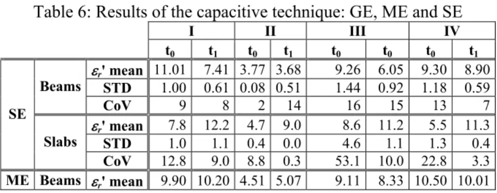
For the first electrode (SE) which can investigates 0.2 to 0.3 cm of depth, a slight decrease in permittivity was observed. This can be interpreted as a decrease in water content between t0 and t1.
Concerning ME and GE, investigating 1 to 2 cm and 7 to 8 cm, respectively, the same results were observed between t0 and t1. This apparent stability reveals the influence of the nearby surface as seen by
SE. Based on this, one can interpret this by an increasing in water content in the slabs at the investigated depths. Thus, a slight gradient of water content was noted.
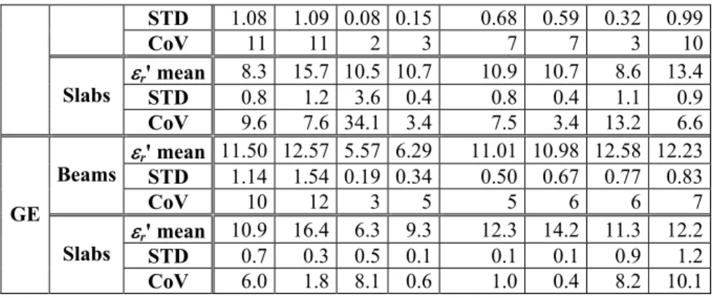
Table 6: Results of the capacitive technique: GE, ME and SE
I II III IV t0 t1 t0 t1 t0 t0 t0 t1 εr' mean 11.01 7.41 3.77 3.68 9.26 6.05 9.30 8.90 STD 1.00 0.61 0.08 0.51 1.44 0.92 1.18 0.59 Beams CoV 9 8 2 14 16 15 13 7 εr' mean 7.8 12.2 4.7 9.0 8.6 11.2 5.5 11.3 STD 1.0 1.1 0.4 0.0 4.6 1.1 1.3 0.4 SE Slabs CoV 12.8 9.0 8.8 0.3 53.1 10.0 22.8 3.3 ME Beams εr' mean 9.90 10.20 4.51 5.07 9.11 8.33 10.50 10.01
STD 1.08 1.09 0.08 0.15 0.68 0.59 0.32 0.99 CoV 11 11 2 3 7 7 3 10 εr' mean 8.3 15.7 10.5 10.7 10.9 10.7 8.6 13.4 STD 0.8 1.2 3.6 0.4 0.8 0.4 1.1 0.9 Slabs CoV 9.6 7.6 34.1 3.4 7.5 3.4 13.2 6.6 εr' mean 11.50 12.57 5.57 6.29 11.01 10.98 12.58 12.23 STD 1.14 1.54 0.19 0.34 0.50 0.67 0.77 0.83 Beams CoV 10 12 3 5 5 6 6 7 εr' mean 10.9 16.4 6.3 9.3 12.3 14.2 11.3 12.2 STD 0.7 0.3 0.5 0.1 0.1 0.1 0.9 1.2 GE Slabs CoV 6.0 1.8 8.1 0.6 1.0 0.4 8.2 10.1
C. Discussions
First, let us analyse the sensitivity of each method called S. This sensitivity can be expressed as:
STD M S 6 Δ = , Eq. 1
where: MΔ is the difference between two measured results of the same technique at two times (STi) or between two techniques at the same time. designates the standard deviation. Assuming that this uncertainty follows a normal distribution in a range containing 97.74 %, the probable scatter due to the uncertainty of the technique is 6 times the STD wide. Results of the computation of STi of the NDT are shown on
STD
Table 7. In this table, the weighted means, standard deviations and coefficients of variance were also computed and presented.
We can consider that only the STi values higher than or equal to 0.5 can be considered for the analysis. At this stage of the project, it is shown that only 13 from 45 cases (28.88 %) and 2 from 5 methods correspond to this condition (see boldface values in Table 7). The majority of these values (10) were those of slabs. Note that the CoV varies in a wide range [2.09 ; 16.88] depending on the technique. The CoV is very low (less than 10%) for the impact-echo, surface waves and multi-offset radar methods. It is also very low for the case of beams (ME and GE) and slabs (GE) of the capacitive method. However, the CoV is vey high for SE and slabs of the ME.
Table 7: Weighted means, standard deviations, variance coefficients and the sensitivity of the NDT methods.
STi Methods Samples Means STD CoV (%)
I II III IV Beams 2534,67 99,01 3,97 0,07 0,14 0,21 0,07 Impact-Echo Slabs 16639,70 340,65 2,09 0,20 0,10 0,17 0,43 Beams 2385,63 72,27 3,12 0,03 0,00 0,25 0,17 Surface waves Slabs 2325,84 74,02 3,24 0,10 0,11 0,03 0,30 Beams - - - - - 0,67 - Multi-Offset Radar Slabs 8,68 0,52 6,05 1,18 0,75 0,91 0,69 Beams 7,42 0,79 10,41 0,65 0,02 0,58 0,07 SE Slabs 8,37 1,35 16,88 0,40 0,39 0,24 0,53 Beams 8,45 0,62 6,73 0,09 0,17 0,24 0,15 ME Slabs 10,80 1,23 11,78 0,78 0,02 0,03 0,50 Beams 10,36 0,77 7,03 0,22 0,17 0,01 0,08 Capacitive GE Slabs 11,34 0,50 4,79 1,65 0,91 0,57 0,28
IV. CONCLUSIONS
In this paper, several repair techniques applied to the tidal zone were carried out and analysed. The study was performed by destructive testing techniques (DT) and non-destructive ones (NDT). The DT methods were used to evaluate the mechanical characteristics: the compressive strength Rc, the static Young’s modulus Estat and the coefficient of Poisson ν, and the durability indicators: the global porosity
accessible to water φ and the dry density of concretes ρdry. The NDT can evaluate: the first symmetrical
Lamb mode frequency (fS1), the surface phase velocities (Vϕ(λ=3cm)) and the permittivity (εr'). In addition,
an inversion algorithm was applied to the impact-echo method to obtain the dynamic Young’s moduli
Edyn and the Poisson coefficients ν. Experiments were curried out to repaired beams, placed in natural
exposure, and fabricated slabs, placed in accelerated conditions. Four different concretes of reparation were considered: wet shotcrete (I), dry shotcrete (II), formed concrete (III) and manual repair (IV). It was shown that the majority of NDT techniques have the ability to be sensitive to the change of properties related to the chloride ingress. Besides, the comparison of mechanical characteristics and durability indicators between concretes having the same constituent (I and II) reveals that the dry shotcrete has the best mechanical and durability performances. The obtained results on slabs are better than those obtained for beams due to the natural conditions nature of the latter.
ACKKNOWLEDGEMENTS
This work is funded by Région Pays de la Loire. Authors are grateful to B. Bigourdan (IFREMER, Brest, France) for controlling ageing of beams in the tidal basin and to F. Jacquemot (CERIB, Epernon, France) for the accelerated tests on slabs.
V. REFERENCES
• [Abraham, 2009]: Abraham O., Villain G., Lu L., Cottineau L-M., Durand O., “A laser interferometer robot for the study of surface wave sensitivity to various concrete mixes”, NDTCE’09, 30th june-3rd july 2009, pp. 597-608. Nantes, France.
• [AFPC-AFREM, 1997]: “Méthodes recommandées pour la mesure des grandeurs associées à la durabilité”, “Recommended methods for measurement of quantities associated to sustainability”, Journées techniques sur la durabilité des bétons, 11-12 december 1997. Toulouse, France,
• [Arliguie, 2007]: Arliguie G., Hornain H., “GranDuBé : Grandeurs associées à la durabilité des bétons”, “GranDuBé : Quantities associated to the concrete durability” Presses de l’Ecole Nationale des Ponts et Chaussées, 2007, 437 p.
• [Chekroun, 2009]: Chekroun M., Le Marrec L., Abraham O., Durand O., Villain G., “Analysis of coherent surface wave dispersion and attenuation for non destructive testing of concrete”, Ultrasonics, 49 (8), 2009, pp. 743-751.
• [Dérobert, 2008]: Dérobert X., Iaquinta J., Klysz G., Balayssac J.P., “Use of capacitive and GPR techniques for non-destructive evaluation of cover concrete”, NDT&E Int., Vol. 41, (2008), pp. 44-52.
• [Gibson, 2005]: Gibson A., Popovics J., “Lamb wave basis for impact-Echo method analysis", J. of Eng. Mech., April 2005, pp. 438-443.
• [NF EN 13412, 2006]: “Products and systems for the protection and repair of concrete structures-Test methods-Determination of modulus of elasticity in compression”, December 2006.
• [NF EN 206-1, 2004]: “Concrete-Part 1: Specification, performance, production and conformity”, April 2004.
• [Perrin, 2010]: Perrin M., Choinska M., Bonnet S., Boukhouna A., Gaillet L., “Repair materials durability of structures in marine environment”, 2nd conference on Marine Environment Damage to Coastal and Historical Structures, MEDACHS 2010, 28 - 30 April 2010, La Rochelle, France.
• [Villain, 2009a]: Villain G., Dérobert X., Abraham O., Coffec O., Durand O., Laguerre L., Baltazart V., “Use of ultrasonic and electromagnetic NDT to evaluate durability monitoring parameters of concrete”, NDTCE’09, 30th june-3rd july 2009, pp. 343-348, Nantes, France.
• [Villain, 2009b]: Villain G., Abraham O., Le Marrec L., Rakotomanana L., “Determination of the bulk elastic moduli of various concrete by resonance frequency analysis of slabs submitted to impact echo”, NDTCE’09, 30th june-3rd july 2009, pp. 881-886, Nantes, France.