Optimization of Furnace Residence Time and Ingots
Positioning during the Heat Treatment Process of Large Size
Forged Ingots
by
Nima BOHLOOLI ARKHAZLOO
MANUSCRIPT-BASED THESIS PRESENTED TO ÉCOLE DE
TECHNOLOGIE SUPÉRIEURE IN PARTIAL FULFILLMENT
FOR THE DEGREE OF DOCTOR OF PHILOSOPHY
Ph.D.
MONTREAL, JANUARY 28TH 2020
ÉCOLE DE TECHNOLOGIE SUPÉRIEURE UNIVERSITÉ DU QUÉBEC
This Creative Commons licence allows readers to download this work and share it with others as long as the author is credited. The content of this work can’t be modified in any way or used commercially.
BOARD OF EXAMINERS
THIS THESIS HAS BEEN EVALUATED BY THE FOLLOWING BOARD OF EXAMINERS
Prof. Mohammad Jahazi, Thesis Supervisor
Department of Mechanical Engineering at École de technologie supérieure Prof. Farzad Bazdidi-Tehrani, Thesis Co-supervisor
School of Mechanical Engineering at Iran university of science and technology
Prof. Vahé Nerguizian, President of the Board of Examiners
Department of Electrical engineering at École de technologie supérieure
Prof. Henri Champliaud, Member of the jury
Department of Mechanical Engineering at École de technologie supérieure
Prof. Louis Gosselin, External Evaluator
Department of Mechanical Engineering at Université Laval
THIS THESIS WAS PRENSENTED AND DEFENDED
IN THE PRESENCE OF A BOARD OF EXAMINERS AND PUBLIC JANUARY 22 ND 2020
ACKNOWLEDGEMENT
I would like to convey my earnest gratitude to my supervisor, Prof. Mohammad Jahazi, whose support, guidance, expertise and patience added considerably to my research experience and without him none of this would have been possible to achieve. I am thankful to him for believing in my accomplishments and providing me with every opportunity to assimilate. I would also wish to thank Prof. Farzad Bazdidi-Tehrani (my co-supervisor) for his kind support, guidance and conveying numerical simulation expertise during my Ph.D. program. He has helped me at all times during my presence in Iran University of Science and Technology (IUST) and after that. I also extend my earnest gratitude to Dr. Mohammad Jadidi, a post-doctoral researcher at IUST, for the fruitful discussions I held with him. He enthusiastically helped me throughout my term with respect to CFD simulation and numerical approaches.
Particular thanks are given to our Industrial partner, Finkl Steel, especially the R & D, Metallurgy and Engineering Departments, for providing real-scale instrumentation and measurements and their collaboration in this project.
Gratitude is also expressed for all CM2P members for their cooperation during the entire journey of my Ph.D.
My utmost gratitude is given to my parents for their outstanding support, kindness, love and constant motivation throughout this journey.
Optimisation du temps de résidence dans le four ainsi que le positionnement de lingots forgés de grande taille lors du processus de traitement thermique
Nima BOHLOOLI ARKHAZLOO
RÉSUMÉ
Les pièces forgées de grande taille sont communément utilisées dans les industries de l’énergie et du transport (arbres de turbines, trains d’atterrissage, etc.). Ces pièces acquièrent leurs propriétés mécaniques supérieures (par exemple, la dureté) grâce à un processus de traitement thermique appelé trempe et revenu. Le processus de revenu (incluant le chauffage et le maintien en chauffe) a lieu dans des fours à gaz et a un impact direct sur les propriétés finales du produit en raison des modifications microstructurales majeures induites par l’effet de la température. Une fois que les paramètres de revenu sont contrôlés (temps et température) les propriétés des matériaux peuvent être généralement optimisées. Distribution non uniforme de la température autour des pièces qui résulte des interactions thermiques à l'intérieur du four ou du positionnement des brames, peut causer une variation dans les propriétés mécaniques d'une extrémité à l'autre de la pièce, une modification de la microstructure ou même initier des fissurations. Par contre, une optimisation du temps de séjour dans le four de traitement thermique peut réduire la consommation d’énergie et éviter les changements microstructuraux indésirables. Cependant, la production industrielle repose principalement sur des corrélations empiriques qui ne sont pas toujours fiables. La prédiction précise de la température en fonction du temps des pièces forgées de grande taille dans les fours de traitement thermique à gaz nécessite un examen quantitatif exhaustif de l'échauffement par la compréhension des interactions thermiques conjuguées complexes à l'intérieur du four. Les limites des études analytiques et la complexité et le coût des expérimentations ont rendu les simulations numériques une solution efficace pour analyser les problèmes de la dynamique des fluides (CFD) dans ce domaine d'étude. Cependant, parmi les études publiées sur les fours à gaz, les fours à petite échelle ou ceux avec un temps de fonctionnement plus court ont été principalement considérés (en utilisant différentes simplifications comme les calculs à l'état stationnaire) et ce principalement en raison de la complexité des phénomènes et des temps de calcul élevés. Par la suite, très peu d’études ont été consacrées à l’amélioration des modèles de chargement des pièces de grande taille dans les fours à gaz et à l’optimisation de leur temps de résidence. De plus, peu d’information est disponible dans la littérature sur les limites et particularités des différentes approches numériques permettant de calculer les interactions thermiques dans le flux réactif turbulent des fours de grande taille chauffés au gaz. À cet égard, l'objectif principal de ce projet est de fournir une analyse quantitative complète de la période transitoire du chauffage et une compréhension des interactions thermiques à l'intérieur du four afin d'optimiser, le temps de
séjour et l'uniformité de la température pendant le traitement thermique. Pour atteindre cet objectif, les étapes ci-après ont été suivies:
La première partie de cette étude, fournit une analyse transitoire complète des caractéristiques de chauffage des pièces forgées de grande taille dans un four à gaz, en utilisant des températures mesurées expérimentalement et des simulations CFD. Un modèle CFD 3D du four à gaz a été généré, incluant, la chambre de traitement thermique, et les brûleurs à gaz. Les interactions entre la chaleur et l’écoulement du fluide, incluant la turbulence, la radiation et la combustion, ont été simultanément considérées dans le modèle en utilisant respectivement les modèles DO et EDM. En outre, l'applicabilité du modèle de radiation S2S a été évaluée pour quantifier l'effet du produit de combustion dans le four et le facteur de forme dû à la radiation durant le transfert de chaleur. Des mesures de températures ont été réalisées à plusieurs endroits grâce à l’instrumentation d’un bloc forgé de grande taille et l'intérieur du four, pour l'analyse expérimentale du processus de chauffage et aussi pour la validation du modèle CFD. Un bon accord a été obtenu avec une erreur maximale d’environ 7% entre les prédictions numériques et les mesures expérimentales. Les résultats ont montré qu'en dépit de l'uniformité de la température du four sans chargement, chaque surface du bloc présentait des vitesses de chauffage différentes après le chargement (chargement simple) ; des différences de température allant jusqu’à 200 k. L’analyse des résultats a également révélée la fiabilité du modèle S2S et a mis en évidence l’importance du facteur de forme du rayonnement pour des besoins d’optimisation pour cette application. Les résultats ont été corrélés avec la géométrie du four, la formation de structures tourbillonnaires et les circulations du fluide autour de la pièce. Les données expérimentales et les prévisions du modèle CFD pourraient être directement utilisées pour l’optimisation du processus de traitement thermique forgées de grande taille.
La deuxième partie de cette étude vise à déterminer l’effet de la configuration du chargement (configuration des chargements multiples) sur la distribution de la température des pièces forgées lors du traitement thermique, afin d’obtenir une meilleure uniformité de température; qui par la suite favorise l’obtention de propriétés mécaniques homogènes. Cette partie vise également l’optimisation du temps de séjour des lingots forgés de grande taille dans un four de revenu, proposant une nouvelle méthodologie hybride combinant des simulations numériques CFD et une série de mesures expérimentales à base d’un dilatomètre à haute résolution. Des simulations transitoires CFD 3D validées par des mesures expérimentales de températures ont été utilisées pour évaluer l’impact des modèles de chargement et du calage (positionnement des cales) sur l’uniformité de la température et le temps de résidence des pièces forgées dans le four. Une analyse transitoire complète des caractéristiques de chauffage des pièces forgées (y compris une analyse des modes de transfert de chaleur) en utilisant quatre configurations de chargement différents a permis de quantifier l’impact des
calages et leurs dimensions sur l’uniformité de la répartition de la température ainsi que sur le temps de séjour des produits. Les résultats ont montré que la non-uniformité de température peut aller jusqu'à 331 K pour un modèle de chargement conventionnel (non optimisé). L'influence positive de l'utilisation des cales et des espaceurs (cales entre les brames) a été approuvée et quantifiée à l'aide de l'approche développée. Il a été possible de réduire les non-uniformités identifiées jusqu'à 32% en modifiant la configuration du chargement à l'intérieur du four de traitement thermique. Cette approche hybride a permis de déterminer le temps de séjour optimal pour les lingots, et aussi permettre son amélioration jusqu’à peu près de 15,5% par rapport à la configuration classique (non optimisée). Cette approche a été validée et pourrait s’appliquer directement à l’optimisation de différents cycles de traitement thermique de pièces forgées de grande taille.
Enfin, la troisième partie de l'étude aborde les détails de la simulation numérique du procédé de traitement thermique de pièces forgées de grande taille dans des fours à gaz à échelle réelle. Plus précisément, l'évaluation du modèle de combustion non-premix avec l'équilibre chimique pour prévision précise de la température des pièces forgées, ainsi que les performances de six modèles de turbulence différents de RANS pour les projections d'analyse thermique sont discutés. À cet égard, les interactions thermiques à différents endroits du bloc forgé et dans des régions critiques telles que la région du brûleur, la stagnation et la région de sillage ont été réalisées à l'aide d'un modèle 3D périodique du four puis validé par des mesures expérimentales. Les résultats ont montré que le modèle périodique avec combustion non-premix est fiable pour l'analyse thermique du processus de traitement thermique avec un écart maximal d'environ 3% par rapport aux mesures expérimentales. Il a également été révélé que le choix du modèle de turbulence avait un effet significatif sur la prévision de la combustion et du transfert de chaleur autour du bloc. La prédiction du rapport ɛ/𝑘 par différents modèles de turbulence a montré une relation significative avec la combustion turbulente (telle que la longueur de la flamme du brûleur) et les prévisions de température du bloc, autour de la région de stagnation. Les modèles 𝑘 − ɛ Standard et réalisable en raison d'une prévision irréaliste de l'énergie cinétique de turbulence (prévision du rapport ɛ/𝑘) ont entraîné une longueur de flamme plus courte et une sous-prévision de la température du bloc forgé autour de la région de stagnation. En suite, le modèle SST 𝑘 − 𝜔 a montré des prévisions raisonnables dans cette région. Le modèle RSM s'est révélé être le modèle de turbulence le plus fiable par rapport aux mesures expérimentales. De plus, un modèle 𝑘 − ɛ réalisable, mis à part une sous-prédiction sur la région de stagnation et la longueur de la flamme, pourrait efficacement prédire la température globale des pièces forgées lourdes avec une précision comparable à celle des données expérimentales et des prévisions du RSM.
Mots-clés: Traitement thermique, simulation CFD, four à gaz, mesures de température,
temps de résidence, mesures expérimentales, approche hybride, modélisation de la turbulence, modélisation de la combustion,
Optimization of furnace residence time and ingots positioning during the heat treatment process of large size forged ingots
Nima BOHLOOLI ARKHAZLOO
ABSTRACT
High-strength large size forgings which are widely used in the energy and transportation industries (e.g., turbine shaft, landing gears etc.) acquire significant mechanical properties (e.g., hardness) through a sequence of heat treatment processes, called Quench and Temper (Q&T). The heating process (tempering) that takes place inside gas-fired furnaces has a direct impact on the final properties of the product due to several major microstructural changes taking place at this step. Therefore, material properties are usually optimized by controlling the tempering process parameters such as time and temperature. A non-uniform temperature distribution around parts, as a result of thermal interactions inside the furnace or loading pattern, may result in the parts property variations from one end to another, changes in microstructure or even cracking. On the other hand, improvement of large products residence time inside the heat treatment furnace can minimize energy consumption and avoid undesirable microstructural changes. However, at the present time, the industrial production is mainly based on available empirical correlations which are costly and not always reliable. Accurate time-dependent temperature prediction of the large size forgings within gas-fired heat treatment furnaces requires a comprehensive quantitative examination of the heating process and an in-depth understanding of complex conjugate thermal interactions inside the furnace. Limitations in analytical studies and complexity and cost of experimentations have made numerical simulations such as computational fluid dynamics (CFD), effective methods in this field of study. However, among the rarely found studies on gas-fired furnaces, small-scale furnaces or those with shorter operation times were mainly considered (using different simplifications like steady-state calculations) because of complexity of the phenomena and large calculation times. Subsequently, there are very few studies on the improvement of the loading patterns of large-size steel parts inside the gas-fired furnaces and their relevant residence time optimization. Moreover, the limitation and strength of different numerical approaches to calculate thermal interactions in the turbulent reactive flow of the large size gas-fired batch type furnaces were addressed by few researchers in the literature. In this regard, the main objective of the present thesis is to provide a comprehensive quantitative analysis of transient heating and an understanding of thermal interactions inside the furnace so as to optimize the residence time and temperature uniformity of large size products during the heat treatment process. To attain this objective, the following milestones are pursued. The first part of this study provides a comprehensive unsteady analysis of large size forgings heating characteristics in a gas-fired heat treatment furnace employing experimentally measured temperatures and CFD simulations. A three-dimensional CFD model of the gas-fired furnace, including heat treating chamber and high momentum natural gas burners, was generated. The interactions between heat and fluid flow consisting of turbulence, combustion and radiation were simultaneously considered using the -k ε , EDM and DO models,
respectively. The applicability of S2S radiation model to quantify the effect of participating medium and radiation view factor in the radiation heat transfer was also assessed. Temperature measurements at several locations of an instrumented large size forged block and within the heating chamber of the furnace were performed for experimental analysis of the heating process and validation of the CFD model. Good agreement with a maximum deviation of about 7% was obtained between the numerical predictions and the experimental measurements. The results showed that despite the temperature uniformity of the unloaded furnace, each surface of the product experienced different heating rates after loading (single loading) resulting in temperature differences of up to 200 K. Analysis of the results also revealed the reliability of the S2S model and highlighted the importance of radiation view factor for the optimization purposes in this application. Findings were correlated with the geometry of the furnace, formation of vortical structures and fluid flow circulations around the workpiece. The experimental data and CFD model predictions could directly be employed for optimization of the heat treatment process of large size steel components. The second part of this study aims to determine the effect of loading pattern (in the multiple loading configurations) on the temperature distribution of large size forgings during the heat treatment process within a gas-fired furnace to attain more temperature uniformity and consequently homogenous mechanical properties. This part also focuses on the improvement of residence time of large size forged ingots within a tempering furnace proposing a novel hybrid methodology combining CFD numerical simulations and a series of experimental measurements with high-resolution dilatometer. Transient 3D CFD simulations validated by experimental temperature measurements were employed to assess the impact of loading patterns and skids on the temperature uniformity and residence time of heavy forgings within the furnace. Comprehensive transient analysis of forgings heating characteristics (including heat transfer modes analysis) at four different loading patterns allowed quantifying the impact of skids and their dimensions on the temperature distribution uniformity as well as products residence time. Results showed that temperature non-uniformities of up to 331 K persist for non-optimum conventional loading pattern. The positive influence of skids and spacers applications was approved and quantified using the developed approach. It was possible to reduce the identified non-uniformities of up to 32 % through changing the loading pattern inside the heat treatment furnace. This hybrid approach allowed to determine an optimum residence time of large size slabs improving by almost 15.5 % in comparison with the conventional non-optimized configuration. This approach was validated and it could be directly applied to the optimization of different heat treatment cycles of large size forgings. The third part of the study addresses the details of the numerical simulation of heat treatment process of large size forgings within real scale gas-fired furnaces. Specifically, assessment of chemical equilibrium non-premix combustion model for accurate temperature prediction of heavy forgings, as well as performance of six different RANS based turbulence models for predictions of turbulent phenomenon were discussed in this context. In this regard, thermal interactions at different locations of the forged block as well as critical regions such as burner area, stagnation and wake region were performed using a one-third periodic 3D model of the furnace and validated by experimental measurements. Results showed that the one-third periodic model with chemical equilibrium non-premix combustion is reliable for the thermal
analysis of the heat treatment process with a maximum deviation of about 3% with respect to the experimental measurements. It was also revealed that the choice of the turbulence model has a significant effect on the prediction of combustion and heat transfer around the block. Prediction of ɛ/k ratio by different turbulence models showed a significant relation to the turbulent combustion (such as burner flame length) and block temperature predictions, around the stagnation region. Standard and realizable 𝑘 − ɛ models, due to an unrealistic over prediction of turbulence kinetic energy (under-prediction of ɛ/k ratio), resulted in shorter flame length and under-prediction on the temperature of the forged block around the stagnation region; While, SST 𝑘 − 𝜔 model showed reasonable predictions in this region. RSM model was found as the most reliable turbulence model compared to the experimental measurements. Meanwhile, realizable 𝑘 − ɛ model apart from some under-prediction on the stagnation region and flame length could effectively predict the overall temperature of the heavy forgings with reasonable accuracy with respect to the experimental data and RSM predictions.
Keywords: Heat treatment, CFD simulation, Gas-fired furnace, Temperature measurements,
Temperature uniformity, Radiation modeling, Loading pattern, Residence time, Experimental measurements, Hybrid approach, Turbulence modeling, Combustion modeling
TABLE OF CONTENTS
INTRODUCTION ...1
CHAPTER 1 LITERATURE REVIEW ...7
1.1 Steel Heat Treatment...7
1.2 Tempering Process ...7
1.3 Heat Treatment Furnaces ...8
1.4 Tempering of Large Size Parts ...9
1.5 Thermal Interactions inside a Gas-Fired Furnace ...10
1.5.1 Conduction ... 11
1.5.2 Convection ... 12
1.5.3 Radiation ... 13
1.5.4 Combustion ... 13
1.5.5 Turbulence ... 14
1.6 Thermal Interactions Analyses inside Heat Treatment Furnaces ...15
1.6.1 Analytical and Semi-Analytical Studies ... 15
1.6.2 CFD Studies ... 16
1.6.3 CFD Analysis of Heat Treatment Furnaces without Combustion ... 18
1.6.4 Gas-Fired Furnaces ... 24
1.7 Challenges and Objectives ...30
CHAPTER 2 NUMERICAL DETAILS FOR THERMAL ANALYSIS OF HEAT TREATMENT PROCESS IN GAS-FIRED FURNACE ...33
2.1 Introduction ...33
2.2 Computational Fluid Dynamics (CFD) ...33
2.3 Navier-Stokes Equations ...34
2.4 Species Transport ...36
2.4.1 The Eddy-Dissipation Model ... 37
2.4.2 Non-premixed Combustion ... 38
2.5 Radiation ...39
2.5.1 P-1 Radiation Model ... 40
2.5.2 Discrete Ordinates Radiation Model (DO) ... 41
2.5.3 Surface to Surface (S2S) Model ... 41
2.6 Turbulence ...42
2.6.1 Reynolds Averaged Navier-Stokes (RANS) ... 42
2.6.2 Two-Equation Turbulence models ... 44
2.6.3 Comparison between Turbulence Modeling Approaches ... 47
CHAPTER 3 EXPERIMENTAL MATERIALS AND METHODS ...51
3.1 Introduction ...51
3.2 Furnace Description ...51
3.4 Flow Measurements ...59
3.5 Calibration Test ...59
3.5.1 Block Measurements and Conductivity Calibration ... 61
3.5.2 Furnace Refractories Heat loss Calibration ... 63
3.6 Laboratory Measurements ...65
3.7 Project Approach ...65
CHAPTER 4 EXPERIMENTAL AND UNSTEADY CFD ANALYSES OF THE HEATING PROCESS OF LARGE SIZE FORGINGS IN A GAS FIRED FURNACE ...69
4.1 Introduction ...72 4.2 Experimental procedures ...74 4.3 Computational Details ...76 4.3.1 Flow simulation ... 76 4.3.2 Radiation modeling ... 77 4.3.3 Combustion modeling ... 77
4.3.4 Numerical simulation procedure and boundary conditions ... 78
4.4 Results and Discussion ...79
4.4.1 Experimental Analysis ... 79
4.4.2 CFD Analysis ... 82
4.5 Conclusions ...91
CHAPTER 5 THERMAL ANALYSIS OF FURNACE RESIDENCE TIME AND LOADING PATTERN DURING HEAT TREATMENT OF LARGE SIZE FORGINGS ...93
5.1 Introduction ...96
5.2 Loading Patterns ...100
5.3 Methodology ...102
5.3.1 Computational Details ... 102
5.3.2 Forgings Temperature Measurements ... 104
5.3.3 Hybrid Approach ... 104
5.4 Results and Discussion ...106
5.4.1 Validation ... 106
5.4.2 Loading Pattern Analysis ... 107
5.4.3 Residence time improvement of forgings during isothermal tempering process ... 115
5.5 Conclusions ...116
CHAPTER 6 CFD SIMULATION OF A GAS-FIRED HEAT TREATMENT FURNACE: ASSESSMENT OF EQUILIBRIUM NON-PREMIX COMBUSTION AND DIFFERENT TURBULENCE MODELS ...119
6.1 Introduction ...123
6.2 Furnace Description ...126
6.3 Numerical Details ...127
6.3.1 Flow and Energy modeling ... 127
6.3.3 Simulation procedure ... 130
6.4 Experimental measurements ...132
6.5 Results and Discussion ...134
6.5.1 Validation of periodic CFD model and combustion approach ... 134
6.5.2 Assessment of turbulence models ... 135
6.6 Conclusions ...148
CONCLUSION ...151
RECOMMENDATIONS ...155
LIST OF TABLES
Page Table 1.1 Temperature validation reported by J. Govardhan et al.
(Govardhan et al., 2011) ...28 Table 2.1 The values of the 𝑘 − ɛ model constants (ANSYS, 2016). ...45
Table 3.1 Thermal conductivity of the gas-fired furnace refractories (Morgan thermal ceramics, 2015). ...63
Table 4.1 Chemical analysis of the test forged ingot used for thermo-physical properties calculation % weight (Finkl Steel Inc.) ...79
Table 4.2 Predicted heat distribution within the furnace. ...82 Table 5.1 Chemical analysis of the investigated steel - Wt. %
(Finkl Steel Inc.). ...105
Table 5.2 Total temperature non-uniformity reduction of forgings for different loading patterns in comparison with
conventional SK loading. ...109
Table 5.3 Residence time reduction of forgings at different loading patterns in comparison with conventional SK loading pattern. ...114
LIST OF FIGURES
Page Figure 1.1 Iron-Carbon phase diagram (Pollack, 1988). ...7 Figure 1.2 (Right): Car-bottom gas-fired heat treatment furnace and (Left):
electrically heated box type heat treatment furnace. ...9 Figure 1.3 Thermal interactions and conjugate heat transfer within a
gas-fired heat treatment furnace. ...11 Figure. 1.4 Temperature dependant thermal conductivity of a steel slab
(Tang et al., 2017). ...12 Figure 1.5 Turbulent combustion visualized by numerical simulation
(Vicquelin, 2010). ...15 Figure 1.6 Prediction of heating and cooling rates with different convection
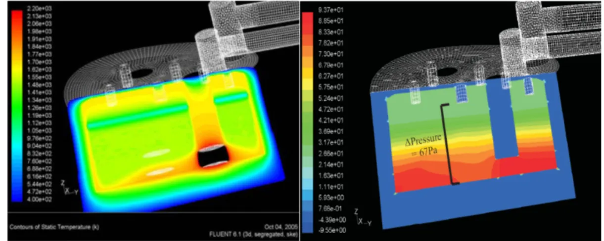
heat transfer coefficients (Gao et al., 2000). ...16 Figure 1.7 Right) pressure and left) temperature distribution prediction by
CFD in the submerged arc furnace (Yang et al., 2006). ...17 Figure 1.8 Temperature distribution prediction of H13 die using CFD
simulation (Elkatatny et al., 2003). ...18 Figure 1.9 Right) temperature contour of air quenched rail head and left) flow field of quenching medium (Gongfa et al., 2014). ...19 Figure 1.10 Streamwise velocity contours of a gas quenching chamber loaded
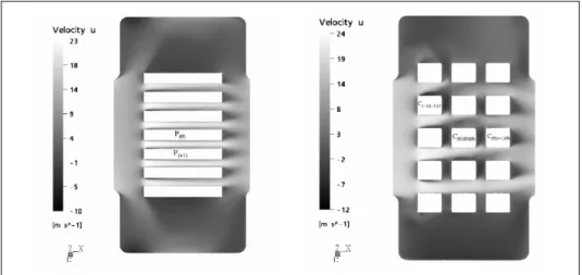
by plates and rectangular ingots (Macchion et al., 2004). ...20 Figure 1.11 Left) velocity distribution and right) temperature in the gas
quenching chamber (Z. J. Wang & Shang, 2010). ...21 Figure 1.12 Contours of temperature evolution in the a) electricaly heated
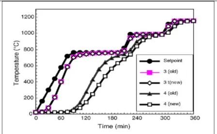
furnace and b) heat treated block (Hao et al., 2008). ...22 Figure 1.13 Optimization of furnace resicence time based on a) heating curves
and b) temperature difference curves inside electretically heated furnace (Hao et al., 2008). ...23 Figure 1.14 Comparison of two different products loading patteren effects
on the heat treatment process inside an electercally heated furnace (Kang & Rong, 2006). ...24
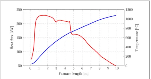
Figure 1.15 Volume average temperature of a billet and its averaged heat flux over the length of furnace (B. Mayr, Prieler, Demuth, Moderer, et al., 2017). ...26 Figure 1.16 Temperature evolution of: a) the heat treating furnace and,
b) the dredging impeller (Yang et al., 2007). ...27 Figure 1.17 Schematic sketch of circular furnace employed by Govardhan et al.
(Govardhan et al., 2011). ...28 Figure 1.18 The lab-scale gas-fired furnace studied by Mayr et al.
(Mayr et al., 2015). ...29 Figure 1.19 Semi industrial gas-fired furnace and its relative measurement
points used in Mayr et al. numerical study (Mayr, Prieler, Demuth, Potesser, & Hochenauer, 2017). ...29 Figure 1.20 Comparison between CFD results and experimental measurements
in a semi-industrial size gas-fired furnace (Mayr, Prieler, Demuth, Potesser, et al., 2017)...30 Figure 2.1 Comparison of computational cost per iteration for different
available RANS models (ANSYS, 2016). ...48 Figure 3.1 Dimensions and geometry of the car bottom gas-fired furnace
in the (a) front view and (b) side view sketches (Bohlooli Arkhazloo et al., 2019). ...51 Figure 3.2 Self-induced turbulence within the gas-fired furnace (Pyradia Inc.). ...52 Figure 3.3 Schematic view of three zones of the furnace. ...53 Figure 3.4 Experimental setup for temperature measurements of unloaded
furnace in different locations of the furnace during the uniformity test. ...54 Figure 3.5 Temperature profile of furnace uniformity test and associated
standard deviation. ...55 Figure 3.6 Procedure of thermocouples embedding on the forged block:
a) filling the drilled hole with iron powder, b) sealing, c) screw fixing and d) wire locating ...56 Figure 3.7 Installed thermocouples in the furnace chimneys for
exhasut heat analysis. ...57 Figure 3.8 Schematic views of 11 thermocouples locations on the
Figure 3.9 Forged ingots including test block: (a) before and (b) after the heat
treatment and opining of the furnace door. ...58 Figure 3.10 Installed flow metering devices on the gas-fired furnace burners to
measure gas consumption. ...59 Figure 3.11 Schematic sketches of 17 thermocouples locations on the
instrumented test block. ...60 Figure 3.12 Instrumented test block loaded on the car-bottom furnace. ...61 Figure 3.13 Temperature dependant thermo-physical properties of the ingot
estimated by JMatPro. ...62 Figure 3.14 Comparison between numerically predicted and measured temperature
evolution of test block’s center point. ...62 Figure 3.15 General energy balance in industrial furnaces
(Mallela et al., 2019). ...64 Figure 3.16 Successive numerical/experimental steps of the research through
optimization objective ...66 Figure 3.17 CFD simulations and subsequent optimization flowchart ...67 Figure 4.1 Dimensions and geometry of the car bottom gas-fired furnace
and (b) Schematic views of thermocouples locations on the instrumented forged ingot. ...74 Figure 4.2 Computational domain, including: (a) boundary conditions and (b)
computational grids. ...79 Figure 4.3 Experimentally measured temperature evolution of TCs on:
(a) different surfaces of the forged ingot, (b) left, top and side surfaces, (c) right surface and (d) their relative temperature
differences. ...80 Figure 4.4 Comparison between numerically predicted and measured
temperatures of the workpiece. ...83 Figure 4.5 Transient contours of temperature evolution of the forged ingot
surfaces and furnace central cross section in 2D and 3D views,
respectively. ...85 Figure 4.6 Transient history of a) total heat flux, b) radiation heat flux, and c) heat transfer coefficient for different surfaces. ...86
Figure 4.7 Contours of temperature distribution on a) right surface, and b) bottom surface of the forged ingot at 𝑡 = 𝑡T/6. ...87 Figure 4.8 Streamlines of planes at a) between fixing bars and perpendicular
to down burner face and b) center of fixing bars. ...89 Figure 4.9 Temperature contours of cross-sectional planes at the center of
the forged ingot in: (a) longitudinal, (b) transversal and (c) lateral planes at 𝑡 = 𝑡T/6. ...90 Figure 5.1 Four different loading patterns of forgings using skids inside
gas-fired heat treatment furnace: a) SK, b) DSK, c) SKC and d) DSKC. ...101 Figure 5.2 Computational domain, including: (a) boundary conditions of
SK case study and (b) computational grids in SKC loading pattern. ...103 Figure 5.3 Validation of CFD simulations in fully loaded furnsce configurations. ..106 Figure 5.4 Temperature evolutions of forgings in conventional
SK loading pattern. ...107 Figure 5.5 Comparison of maximum identified temperature non-uniformities
for different loading patterns at the surface of: a) large size, block and b) slab. ...108 Figure 5.6 Contours of temperature distribution in central cross sections of
forgings at 𝑡 = 𝑡𝑇/6. a) SK, b) DSK, c) SKC, and d) DSKC. ...111 Figure 5.7 Transient history of a) maximum non-uniformity of forgings,
b) total heat flux, c) convection heat transfer coefficient, and d) radiation heat flux on forgings surfaces with two different sizes of spacer skids. ...112 Figure 5.8 Forgings average temperature evolution: a) large size block, b) slab
and derivative of temperature evolution with respect to time, c) large size block, and d) slab in different loading pattrens. ...113 Figure 5.9 Hardness measurements after isothermal tempering at 582oC
for different holding times. ...116 Figure 6.1 Computation model boundary conditions. ...131 Figure 6.2 Grid resolution of furnace domain and its details including gas-fired
Figure 6.3 CFD model inputs a) temperature dependent thermo-physical properties of steel parts estimated by JMatPro software, and b) measured furnace gas consumption. ...133 Figure 6.4 Periodic CFD model including equilibrium non-premix
combustion model validation. ...134 Figure 6.5 Comparison of temperature predictions by various turbulence
models and experiment at different locations of forged block: a) stagnation point, b) side wall, and c) wake region at 𝑡 = 𝑡𝑇/6. ...136 Figure 6.6 Time averaged temperature contours of a high momentum lower
burner predicted by a) Standard 𝑘 − ɛ, b) Realizable 𝑘 − ɛ, c) standard 𝑘 − 𝜔, d) SST 𝑘 − 𝜔, e) RNG, and f) RSM models. ...138 Figure 6.7 Mean temperature contours of lower burner as predicted by
a) standard 𝑘 − ɛ, b) realizable 𝑘 − ɛ, c) standard 𝑘 − 𝜔, d) SST 𝑘 − 𝜔, e) RNG 𝑘 − ɛ, and f) RSM turbulence models. ...140 Figure 6.8 Distribution of OH mass fraction in burner’s axial direction. ...141 Figure 6.9 Influence of turbulence modeling on axial distribution of
a) mean mixture fraction, b) mixture fraction variance, c) scalar
dissipation rate, and d) ɛ/k ratio at burner centerline. ...143 Figure 6.10 Turbulence kinetic energy contours of lower burner region by
a) realizable 𝑘 − ɛ, b) SST 𝑘 − 𝜔, and c) RSM turbulence models. ...144 Figure 6.11 Temperature distribution of large size block predicted by three
turbulence models at non-dimensional heights of a) 𝑌/𝐻=0.25, b) 𝑌/𝐻=0.5, and c) 𝑌/𝐻=0.75. ...146 Figure 6.12 Streamlines at a plane along with lower burner centerline by
LIST OF ABBREVIATIONS
2D Two dimensional
3D Three dimensional CFD Computational Fluid Dynamics DO Discrete ordinates model
DSK Double Skid
DSKC Double skid + Central spacer skid DTRM Discrete Transfer Radiation Model HRC Rockwell C hardness
EDM Discrete ordinates model EDC Eddy dissipation concept Q&T Quench and temper
RANS Reynolds-averaged Navier–Stokes equations RNG Re-normalization group
RSM Reynolds stress model RFL Rich Flammability Limit RTE Radiative transfer equation RTE Radiative transport equation S2S Surface to surface
SK Single Skid
SKC Single Skid + Central spacer skid SST Shear stress transport
TC Thermocouple
TKE Turbulence kinetic energy
LIST OF SYMBOLS Latin symbols a Absorption coefficient A Surface (m2) d Characteristic dimension (m) Dt Turbulence diffusivity C1ɛ ,C2ɛ ,C3ɛ Constants in 𝑘 − ɛ equations
Cg, Cd Constants in mixture fraction variance transport equation
𝐸 Energy (J)
Fij View factor between surface 𝑘 and surface j
f Mean Mixture fraction 2
f′ Mixture fraction variance
Gk Turbulence kinetic energy production due to velocity gradient
Gb Turbulence kinetic energy production due to buoyancies
Gω Eddy dissipation rate production due to velocity gradient
g Gravity (m s/ 2) z
i
J Diffusive flux of chemical species h Enthalpy (J kg/ )
h0 Convection heat transfer coefficient (W/m2.K)
H Block height
I Radiation intensity
K Conductivity (W/m.K)
k Turbulence kinetic energy (m2 /s2) eff
k Effective thermal conductivity
L Furnace length in longitudinal direction ls Turbulence length scale
m
g Mass flux ( 2 / m . kg s) n Refractive indexOH Hydroxide
p Pressure (Pa)
i
q The generic source term r
q Reaction heat term s
q The generic source term 𝑟⃗ Position vector
z
R Production rate of z component th
r
R Net production of a specie in a reaction ,
z r
R Production rate of z component th
Re Reynolds number (ud μ)
s Path length
sr Direction vector
sr′ Scattering direction vector z
S Source term of z component production th
Sc Schmidt number
t Time (s)
T
Temperature (K)T
t Total heat treatment time i
u Reynolds-averaged velocity in tensor notation i
u′ Resolved fluctuating velocity components U Time averaged velocity
Vs Velocity scale
, Y, Z
X Direction of coordinate axes
Greek symbols
ε Turbulence dissipation rate (m2 /s3) k
ε Surface emissivity
ν Kinematic Viscosity (m s2/ ) t
μ Turbulence eddy viscosity (kg m s. / ) k
Γ Turbulence kinetic energy diffusion coefficient k
Γ Eddy dissipation rate diffusion coefficient ρ Density (kg m/ 3 ) k ρ Surface reflectivity , k ε
σ σ Prenatal number for the kinetic energy and dissipation rate
respectively t
σ Constant in mixture fraction variance equation , s
σ σ Stefan-Boltzmann constant and scattering coefficient ' ' i j u u ρ Reynolds stress (kg/ m.s2 ) ′ Ω Solid angle
ω Specific dissipation rate
ϕ Phase function
λ Wavelength
ij
τ
Viscous stress tensorSuperscripts
' Fluctuations with respect to a Reynolds averaging - Time averaging function
→ Vector
Subscripts
h Hot , , i j k Tonsorial indices O Out ox Oxygen R Combustion reaction Sec Secondary s Source T Total t Turbulence z z species th λ Spectral parameter Abbreviation 3D Three dimensional
CFD Computational Fluid Dynamics DO Discrete ordinates model
DSK Double Skid
DSKC Double skid + Central spacer skid EDM Discrete ordinates model
HRC Rockwell C hardness
RANS Reynolds-averaged Navier–Stokes equations RNG Re-normalization group
RSM Reynolds stress model RFL Rich Flammability Limit RTE Radiative transfer equation RTE Radiative transport equation SST Shear stress transport
SK Single Skid
SKC Single Skid + Central spacer skid TKE Turbulence kinetic energy
INTRODUCTION
A significant number of high-strength steel parts such as medium-carbon low-alloy steel used for different critical applications in energy and transportation, such as turbine shafts and landing gears, acquire their required properties through a sequence of heat treatment processes often called Quench and Temper (Q&T) (Bhadeshia & Honeycombe, 2017). This is to attain some important properties such as hardness, toughness, corrosion resistance and so on. Optimum process, which is an operation including the controlled heating and cooling of metals and alloys in the solid state to obtain specific mechanical characteristics, is a critical point and one of the most important parts of metallurgical engineering procedures. The Tempering (a heating process after the initial casting and open die forgings) is one of the most vital steps of the heat treatment having a direct influence on final delivered mechanical properties of the products (Totten, 2006).
Generally, gas-fired furnaces are used in the steel plants to carry out the tempering process. Heat transfer to the products primarily depends on temperature distribution inside the furnace and it significantly affects the quality of the final part. Besides, the time of tempering directly affects the acquired mechanical properties after the process. Hence, temperature and time are usually used to optimize the final material properties of the products. The problem becomes more acute and critical when it comes to the heat treatment of large size products for energy and transportation industries (Bohlooli Arkhazloo et al., 2019).
A non-uniform temperature distribution may result in the property variation from one end to another of the part, changes in microstructure, or even cracking. Different locations of blocks inside the furnace, considering their mutual heat transfer and also between the blocks and the heat sources may experience non-uniform heat transfer and consequently a non-uniform heat treatment. Improvement of the loading patterns within the furnace can significantly increase the temperature uniformity of the product during the process. Besides, it can also reduce the residence time of products by increasing the heating rates of the work piece as a result of changing in the heat transfer pattern.
On the other hand, reduction of residence time of large products inside the heat treatment furnace can minimize energy consumption and avoid undesirable microstructural changes. Required time for only one step of different stages of heat treating process can be more than 62 hours in the case of large size products (Gur & Pan, 2008). Therefore, optimization of forgings ingots residence time inside gas-fired heat treating furnaces is of great importance in the steel making industry. This improvement not only provides a better treatment, but also leads to a cost effective production. The importance of residence time is more notable where a significant number of large size ingots should be treated every day. In other words, even a small reduction in the residence time of one product can lead to a considerable energy savings. Thus, predicting and controlling the products’ transient temperature is an essential task in the heat treatment process both from the performance and the cost points of view.
The current practice in industry for the heating cycle schedule is based on empirical correlations and is mostly limited to monitoring of the furnace temperature as a function of the furnace load (Zhang, Wen, Bai, Chen, & Long, 2009). Empirical correlations, however, cannot be used to accurately predict temperature distribution in the products and very often large deviations with the loading pattern or furnace configurations, are observed (Gur & Pan, 2008; Hao, Gu, Chen, Zhang, & Zuo, 2008; Wang et al., 2008).
Therefore, accurate time-dependent temperature prediction of the large size parts inside the gas-fired heat treatment furnaces necessitates a quantitative examination of the transient heating and comprehending of thermal interactions within the furnace. This analysis can deliver information about the temperature evolution of products and improvement of temperature uniformity, residence time and loading pattern of large-size steel parts in gas-fired heat treating furnaces. However, understanding the complexities of the thermal interactions along with the turbulent flow field as well as combustion and radiation within the gas-fired heat treatment furnace is very challenging. These phenomena imposing strong non-linear thermal boundary conditions make the analytical studies, which are generally limited to linear problems, very complex and insufficient for accurate predictions (Gao, Reid, Jahedi, & Li, 2000). On the other hand, experimentation of large-size products in the large scale
furnaces and reliable data acquisition is very challenging and expensive. Recently, computational fluid dynamics (CFD) offering simultaneous analysis of turbulent fluid flow, combustion and conjugate heat transfer has been employed to study large size industrial furnaces (Chattopadhyay, Isac, & Guthrie, 2010). Different furnaces such as electrically heated or gas quenching ones have been studied using CFD. However, very few studies focus on the simulation of large-size heat treatment inside gas-fired batch-type furnaces due to their complexity, as a result of reactive flow combined with turbulent transport process and conjugate heat transfer including absorbing and emitting hot combustion products and long processing. Hence, the number of published papers in the case of heat treatment furnaces is few and most of the limited numerical studies have been devoted to one aspect of the process (i.e., furnace chamber and its details such as burners or product heating characteristics, solely) rather than simultaneous analysis of furnace thermal interactions (such as turbulent combustion and radiation heat transfer) and its details including the product.
Considering the importance of accurate transient temperature prediction of large-size products inside the gas-fired heat treatment furnaces and the lack of relevant information, the first objective of the present thesis was on the experimental analysis and CFD simulations of large-size products’ heat treatment inside gas-fired furnaces. Comprehensive analysis of the conjugate heat transfer in the heat treatment process as well as identification of a correlation between non-uniformity sources including furnace geometrical parameters (size, location of burners and skids), loading pattern and vortical structures inside the furnace was other secondary objectives of this study.
There are few studies on the improvement of large-size steel parts loading patterns inside the gas-fired furnaces and their relevant residence time optimization. Therefore, investigation of the loading patterns effect on temperature uniformity of large size forged ingots as well as reduction of residence time inside the large size gas-fired furnaces, were other objectives of the present thesis.
Due to the lack of enough systematic evaluation of the strengths and limitations of different CFD approaches for the prediction of thermal interactions within the furnace, including turbulence and combustion, the fourth objective of the present study was set to address this limitation in the literature. In other words, finding an accurate combination of CFD models that could deliver reliable prediction of burner domain (flow field) and product temperature (scalar) with reasonable computational cost was the fourth objective of the present study. A detailed analysis of turbulent combustion phenomena in the furnace was another secondary objective of this part.
The present thesis is organized, as follows:
1. The thesis starts with an overview on the heat treatment process of large-size forgings inside gas-fired furnaces in chapter 1. Different thermal interactions involved in the heat treatment and their relative numerical approaches to be predicted by the CFD simulation are discussed. Finally, the state-of-the-art on the analysis of heat treatment of large size products inside gas-fired furnaces, their loading pattern and residence time as well as numerical approaches to predict the process are identified.
2. Chapter 2 presents the details of the numerical approaches employed for simulating the thermal interactions inside the gas-fired furnace. After a mathematical description of each model, strengths and limitations of different approaches are discussed.
3. The elaboration of the industrial and laboratory scale experimental measurements are presented in chapter 3. Details of instrumentations and measurements in a real scale gas-fired heat treatment furnace (loaded large size forged ingots), as well as laboratory scale experimentations are presented. Also, details of a calibration test process to evaluate the measurement accuracy and employed thermo-physical properties are discussed in this chapter.
4. Chapter 4 focuses on the experimental and numerical analyses of large size forgings transient heating inside the gas-fired heat treatment furnace in the single loading
configuration. Heat transfer histories of different locations of the parts inside the furnace as well as temperature uniformity analysis of the forgings based on the analysis of conjugate heat transfer are presented. Details of the cause of temperature non-uniformities including furnace geometrical design, loading pattern and fluid flow circulation and their correlation with heat transfer modes (radiation, convection) are discussed.
5. Chapter 5 discusses the effect of loading pattern on the temperature homogeneity of the large-size products during the heat treatment process. The chapter also proposes a new hybrid methodology (including CFD simulation and experimental measurements) to optimize the residence time of large size forgings inside the heat treatment furnace during different stages of tempering.
6. Chapter 6 presents details of CFD simulation of a gas-fired furnace comparing different numerical approaches to predict the thermal interactions inside the gas-fired heat treatment furnace. Details of turbulence and combustion modeling and their relative strengths and limitations in this particular application are discussed. Finally, after comprehensive analysis of numerical techniques, a computationally effective methodology to predict the heat treatment process of large-size forgings inside gas-fired heat treatment furnaces is proposed.
A summary covering all the concluding remarks concerning chapters 4 to 6 is presented in the Conclusions section to link the outcomes of the thesis and present original contributions of the study toward the thesis initial objectives.
CHAPTER 1 LITERATURE REVIEW 1.1 Steel Heat Treatment
Heat treatment is a process that encompasses the controlled heating and cooling of metals and alloys in the solid state to achieve certain mechanical characteristics such as hardness, strength, flexibility, machinability and reduction of residual and internal stresses. The heat treatment process takes place based on the steel microstructural transformation as a function of temperature and chemical composition of an alloy (Bhadeshia & Honeycombe, 2017) (See Fig. 1.1).
Figure 1.1 Iron-Carbon phase diagram (Pollack, 1988).
1.2 Tempering Process
Tempering is a thermal treatment process that is often carried out in gas-fired heat treatment furnaces (for large-size product) after the quench. The aim is to modify the microstructure of
the quenched part to acquire desired mechanical properties such as hardness, toughness, ductility and dimensional stability (Speich & Leslie, 1972). The main two parameters that control the tempering process are temperature and time at temperature. Depending on chemical composition of a specific steel, its primary microstructure, and heating rate, different microstructural changes takes place during certain temperature intervals and time. Inaccurate selection of time and temperature of tempering can affect final mechanical properties and can even produce cracks in the part (Canale, Yao, Gu, & Totten, 2008). There are several methods to determine proper time and temperature of the tempering process. Methods like Liščić and Filetin’ correlation (Liščić & Filetin, 1987) using linear regression analysis for a specific temperature range of tempering have been used to calculate the tempering temperature-time condition. Other methods like Holloman-Jaffe equation (Totten, 2006) were developed to predict the hardness of tempered steel parts. In all these equations, having an accurate prediction of parts’ temperature during the heating up to the target temperature (non-isothermal tempering) and soaking at the temperature (isothermal tempering) is important.
1.3 Heat Treatment Furnaces
Heat treatment furnace that provides the heat treatment medium inside, is one of the most vital equipment of heat treatment procedure which should be comprehensively studied to achieve optimum heat treatment of metals. There are several types of heat treatment furnaces that can be categorized based on their shape and movement of products within them (such as box furnaces, pit furnaces or tip-up furnaces) or the energy used in them (like electrical heated furnace or gas-fired heat treatment furnaces). Among different types of furnaces Gas-fired heat treatment furnaces are extensively used for large-size high-strength steel products such as medium-carbon low-alloy steels for different critical applications in the energy and transportation industries. Natural gas usage in these furnaces provides the increased heat treatment rate and reliable burning (Totten, 2006). Final material properties are usually optimized by tempering parameters modification (such as temperature, time, etc.) in these heat treatment furnaces (Yan, Han, Li, Luo, & Gu, 2017). To analyze these furnaces, burners
which provide the heat input as a result of combustion of the natural gas by oxygen should be studied comprehensively (Purushothaman, 2008).
Figure 1.2 (Right): Car-bottom gas-fired heat treatment furnace and (Left): electrically heated box type heat treatment furnace.
1.4 Tempering of Large Size Parts
Large-size products, due to the significant temperature variation between their surface and center, contain different microstructures which in turn response differently to the tempering process (Talebi, Ghasemi-Nanesa, Jahazi, & Melkonyan, 2017). Besides, non-uniform temperature distribution in such parts within gas-fired furnaces may result in non-uniform properties in different locations of the final product or even cracking. Therefore, temperature distribution uniformity is of great importance for the quality of the final products (Gao et al., 2000; Gur & Pan, 2008). Further, due to their large sizes a lot of energy is used in these furnaces (Kang & Rong, 2006; B. Mayr, Prieler, Demuth, Moderer, & Hochenauer, 2017). Therefore, predicting, controlling and subsequently optimizing the temperature distribution of such parts is a necessary task to increase the product quality and reduce the production cost (Hao et al., 2008). However, an exact prediction of the furnace temperature distribution and, consequently, the temperature experienced by the product is difficult and the heating cycle schedules are mainly based on the available empirical correlations (Kang & Rong, 2006). These correlations are usually valid for specific ranges of temperature and defined as a function of the furnace load and simple loading patterns of the parts inside the furnace
(Canale et al., 2008; Korad, Ponboon, Chumchery, & Pearce, 2013). Hence, large deviations in the case of large-size products multiple loading patterns are observed (Cheng, Brakman, Korevaar, & Mittemeijer, 1988; Gao et al., 2000; Primig & Leitner, 2011). On the other hand, most of the metallurgical studies assume a constant heating rate in different locations of the part, which is far from the reality and proves the need for accurate determination and prediction of temperature evolution inside the gas-fired heat treatment furnaces and subsequent analyses based on these temperature profiles.
An accurate temperature prediction of parts necessitates a quantitative analysis of thermal interactions and their subsequent roles on the transient heating of large size parts inside gas-fired heat treatment furnaces as detailed in the following sections.
1.5 Thermal Interactions inside a Gas-Fired Furnace
Heat is a form of energy that exchanges between several mediums due to temperature differences. This transfer of energy which always takes place from the higher temperature field to the lower one, according to the first law of thermodynamics, is the basis of the heat transfer (Incropera, Lavine, Bergman, & DeWitt, 2007). Gas-fired heat treatment furnaces transfer heat to the different location of parts through the three modes of heat transfer: radiation, convection and conduction. As it can be seen in the schematic view of interactions inside a heat treating furnace (Fig. 1.3) the three modes of heat transfer are playing their role in a conjugate situation. Therefore, any analytical, experimental or numerical study should consider the conjugate heat transfer to analyze the heat transfer rates. It should be noted that these heat transfer modes take place in combination with the two main fluid flow related interactions (combustion and turbulence) which will be discussed in the following sections.
Figure 1.3 Thermal interactions and conjugate heat transfer within a gas-fired heat treatment furnace.
1.5.1 Conduction
The conduction heat transfer is the most significant mode in a solid medium. The heat transfer rate through a planar layer according to the Fourier’s law is:
dT Q kA
dx = −
& (1.1)
In this equation, k, as thermal conductivity, is the material property that represents the ability to conduct the heat in a material whether solid or fluid flow. Thermal conductivity of many materials changes with temperature. This is also true for other thermo-physical properties of material like specific heat. For instance, Fig. 1.4 shows the variation of a carbon steel thermal conductivities and specific heats over a wide range of temperatures used by Tang et al. (Tang et al., 2017) in their study. JMatPro software (Danon, Cho, De Jong, & Roekaerts, 2011) was reported to be a reliable tool for the calculation of temperature dependent thermal conductivities of different alloys (B. Mayr, Prieler, Demuth, Moderer, et al., 2017; Prieler, Mayr, Demuth, Holleis, & Hochenauer, 2016; Tang et al., 2017).
Figure. 1.4 Temperature dependant thermal conductivity of a steel slab (Tang et al., 2017).
1.5.2 Convection
The Newton’s rule of cooling describes the rate of convection heat transfer (the heat transfer that is actuated by the flow motion usually takes place with the mass transfer), Q&conv, based on the temperature gradient, the differences between the hot surface (T )h and the ambient fluid temperature ( )T and the heat transfer area, a A are as below: s
(
)
conv h A To s h Ta
Q& = − (1.2)
In this equation h is the convection heat transfer coefficient. Several investigations in the o heat treatment field show that the convection heat transfer plays an important role in the heat transfer in this process (Bhadeshia & Honeycombe, 2017; Totten, 2006). Although in some furnaces such as electrically heated vacuum furnaces (Gao et al., 2000) the convection heat transfer can be neglected, in majority of the furnaces the convection can be considered as a significant phenomenon in the process. This heat transfer mode is dominant, especially at low temperatures where the furnace undergoes the heating to reach to the soaking temperature. The convection heat transfer is highly correlated with turbulence in turbulent fluid flow.
1.5.3 Radiation
Radiation heat transfer is the energy emitted by the matter (photons) in the form of electromagnetic waves due to changes in the electronic configuration of atoms as a result of temperature in vacuum (without the presence of matter) or transparent mediums (solid and fluid). The Stefan-Boltzmann law for a black surface, calculates the total radiated energy per unit surface area per unit time (E ) as a function of the fourth power of object’s (black body) b temperature as follows (Howell, Menguc, & Siegel, 2015):
4
b
E =σT (1.3)
Where the temperature is in Kelvin and σ =5.67 10 Js m K× -8 -1 -2 -4 is the Stefan-Boltzmann constant. For the gray body which does not absorb or emit the full amount of radiation and normally radiates a small amount of that, the total energy, considering the emissivity, becomes (Incropera et al., 2007):
(
4 4)
a b
A T
Q&= εσ −T (1.4) The radiative transfer equation (RTE) in a medium that participates in the radiation heat transfer (a medium with absorption, emission, and scattering effect) can be formulated as follows (Danon et al., 2011):
4 4 2 0 ( , ) ( ) I( , ) I( , ) ( , ) 4 s s dI r s T a r s an r s s s d ds π σ σ σ φ π π ′ ′ + + = +
Ω r r r r r r r ur (1.5) Where I is the radiation intensity and (a+ ) represents the optical thickness of the medium. σs The definition of all the variables and related units are provided in the nomenclature section.1.5.4 Combustion
Hydrocarbon fuel sources such as methane or natural gas can react with oxygen to provide combustion and subsequently thermal energy or heat.
4 2 2 2 2 2
The oxygen availability and operating temperature can change the combustion efficiency and also the combustion products. Incomplete combustion and CO production will take place in combustion with insufficient oxygen content. Besides, the excess air, which means excess oxygen, can affect the ratio of available heat. Combustion in any gas-fired heat treatment furnaces plays the most important role in the system because:
• Combustion facilitator devices such as burners can be considered as the inlet boundary condition for the main system such as a furnace.
• Combustion has a direct interaction with the radiation, convection and turbulence which have their own impacts on the final goal.
Therefore, the combustion prediction in any combustion included application such as gas-fired heat treatment furnaces should be thoroughly investigated.
1.5.5 Turbulence
Almost all fluid flows which we encounter in the world are turbulent. Turbulent flows can be usually observed in numerous natural and industrial cases like impingement flows or burner combustions (Fig. 1.5). The boundary layers and the wakes around and after bluff bodies such as cars, airplanes, buildings and large-size steel parts in the heat treatment furnaces are turbulent. In the turbulent flow field of study, the parameters such as velocity are decomposed in two parts of a time-averaged, 𝑈 , which is independent of time (when the average flow is steady), and a fluctuating part, 𝑢́ , which means that 𝑢 = 𝑈 + 𝑢́ . There is no exact definition of turbulent flow, but it has a number of characteristic features such as irregularity, continuity, diffusivity, large Reynolds numbers, a three-dimensional nature (Cant, 2001; Tennekes, Lumley, & Lumley, 1972). These characteristics can be found in several gas-fired heat treatment furnaces which are designed to have a self-induced turbulence. The high momentum of combustion products, with a large Re number, are in continuum interactions and provide 3D circulation inside the furnace.
Figure 1.5 Turbulent combustion visualized by numerical simulation (Vicquelin, 2010).
1.6 Thermal Interactions Analyses inside Heat Treatment Furnaces 1.6.1 Analytical and Semi-Analytical Studies
Thermal interactions inside the gas-fired heat treatment furnaces importing strong non-linear thermal boundary conditions to the loads make the thermal analysis of heat treatment process very difficult. In the literature Chapman et al. (Chapman, Ramadhyani, & Viskanta, 1990) in a semi-analytical study, assessed various material properties on the efficiency of heat treating process in a direct fired batch reheating furnace. Gao et al. (Gao et al., 2000) using heat conduction rule in solids, developed an analytical, practical virtual sphere method to estimate the equilibrium time and heating/cooling rate in heat treatment furnaces. Their results proved that the convection heat transfer rate could significantly differ from the empirically calculated h values for specific furnaces. Singh et al. (Singh, Talukdar, & Coelho, 2015) in their semi-analytical studies developed a heat-flow model to estimate temperature evolution of products in different heat treatment processes such as heating in electrically furnaces, air and water quenching. However, analytical analyses are generally limited to linear problems
and they become very complicated in gas-fired furnaces where strong non-linear transient condition and interactions are present.
Figure 1.6 Prediction of heating and cooling rates with different convection heat transfer coefficients (Gao et al., 2000).
Although the advantage of these types of studies is in their simplicity and applicability in different case studies, the fact that the today’s industry needs reliable and optimal data for optimization of product quality and product price, illustrates the need for studies with more details and accuracy. The need for specification of real convection heat transfer coefficient, accurate combustion prediction and suitable radiation simulation to provide a better optimization of time residency and positioning plan, specify the value of high order numerical simulations in this field of study.
1.6.2 CFD Studies
In this context, major advances have been made in development of high performance computational facilities allowing for the simulation of large size furnaces. Studies such as those of Jaklic et al. (Jaklič, Glogovac, Kolenko, Zupančič, & Težak, 2002) and Tagliafico et
al. (Tagliafico & Senarega, 2004) using finite-difference and finite element based methods added more details to the analysis of load-furnace heating characteristics. Recently, computational fluid dynamics (CFD) offering simultaneous analysis of turbulent fluid flow, combustion and conjugate heat transfer has been used to simulate thermal flow field in various metallurgical processes (Szajnar, Bartocha, Stawarz, Wróbel, & Sebzda, 2010; S. F. Zhang et al., 2009; Zhou, Yang, Reuter, & Boin, 2007) (See Fig. 1.7). Yang et al. (Yang et al., 2006) using the ANSYS Fluent software (ANSYS, 2016) performed CFD evaluation of various metallurgical applications including: melting of aluminum scrap in a rotary furnace, molten hot metal flow in a coke-bed blast furnace, electric arc furnace and gas-fired heat treating furnaces. They used 𝑘 − ɛ turbulence model alongside with the EDM combustion model. Several radiation models including, P-1, DTRM and Monte Carlo model (MCM) have been evaluated in different industrial furnaces. The capability of these approaches to predict the thermal interactions inside the furnace has been confirmed by the authors. They also presented several data, including temperature evolution, melting curves and gas consumption profiles proving the CFD applicability in predicting flow, temperature, mass fraction and reaction distribution. Wang et al. (J. Wang et al., 2008) predicted the temperature field of a gas quenching furnace using CFD simulation and Cosentino et al. (Cosentino, Warnken, Gebelin, & Reed, 2013) investigated the non-uniform quenching effect on the product properties.
Figure 1.7 Right) pressure and left) temperature distribution prediction by CFD in the submerged arc furnace (Yang et al., 2006).
1.6.3 CFD Analysis of Heat Treatment Furnaces without Combustion
One of the most basic investigations of heat treatment process using CFD is the study of Elkatatny et al. (Elkatatny, Morsi, Blicblau, Das, & Doyle, 2003) who presented a CFD simulation of high-pressure gas quenching of H13 die in a vacuum heat treatment furnace (See Fig. 1.8). They suggested that a steady state simulation can be effectively used instead of complete transient simulation in order to reduce the computational cost. It has been reported that the CFD results were in good agreement with the experimental data and the steady state solution was capable of accurate prediction of quenching treatment.
Figure 1.8 Temperature distribution prediction of H13 die using CFD simulation (Elkatatny et al., 2003).
Gongfa et al. (Gongfa et al., 2014) investigated the air quenching of heavy rail-head U71Mn in both internal and external fields product using CFD. They could establish the flow distribution, streamlines and temperature contours in internal and external fields. Using the cooling rate calculation, provided by CFD simulation, they reported phase transformation on the basis temperature gradient. Bergman (Bergman, 2012) provided a 2D simulation of a heat treatment furnace, including the gas fluid flow and heat transfer into the product (turbine structure). The significant impact of Reynolds number and buoyancy on the heat transfer rate was reported. Besides, in the case of turbulence modeling, according to the authors, -k ω model was proved to be a more reliable model in comparison to the standard -k ε and the realizable -k ε models to predict the heat flux for highly turbulent fluid flow. Wang et al. (J.