HAL Id: hal-00753113
https://hal.archives-ouvertes.fr/hal-00753113
Submitted on 17 Nov 2012
HAL is a multi-disciplinary open access
archive for the deposit and dissemination of
sci-entific research documents, whether they are
pub-lished or not. The documents may come from
teaching and research institutions in France or
abroad, or from public or private research centers.
L’archive ouverte pluridisciplinaire HAL, est
destinée au dépôt et à la diffusion de documents
scientifiques de niveau recherche, publiés ou non,
émanant des établissements d’enseignement et de
recherche français ou étrangers, des laboratoires
publics ou privés.
RCL : A new Method for Cross-Layer Network
Modelling and Simulation
Tiado Mahamadou Issoufou, Riadh Dhaou, André-Luc Beylot
To cite this version:
Tiado Mahamadou Issoufou, Riadh Dhaou, André-Luc Beylot. RCL : A new Method for
Cross-Layer Network Modelling and Simulation. 7th IFIP International Conference on Mobile and Wireless
Communication Networks, MWCN’05, Sep 2005, Marrakech, Morocco. �hal-00753113�
RCL : A new Method for Cross Layer Network Modelling and Simulation
AbstractThe evolution from wired network systems to wireless environments such as Ad-hoc networks enables the emerging of cross layer systems to improve the wireless network performance. Efficient methods, that may either produce or update cross layer conceptual models have to be considered. Those models allow an efficient organisation of the wireless systems. In our approach, a cross layer conceptual model is composed of : cross
layer interaction models and interactions description arrays, produced by the Reverse Cross-Layer (RCL) method
that we proposed. The method has been applied to a chosen protocol stack.
Index Terms Ad hoc Network, Cross layer Method.
Authors :
Mahamadou ISSOUFOU TIADO, [email protected] [email protected] téléphone : +33 5 61 58 80 17 Riadh DHAOU, [email protected] Phone: +33 5 61 58 80 07 André-Luc BEYLOT, Email: [email protected] Tel (+33) 5.61.58.80.00 Affiliation :
ENSEEIHT IRIT Lab 2, rue Camichel BP 7122
31071 Toulouse cedex 7 France fax : +33 5 61 58 80 14
1
Abstract The evolution from wired network systems to wireless
environments such as Ad-hoc networks enables the emerging of cross layer systems to improve the wireless network performance. Efficient methods, that may either produce or update cross layer conceptual models have to be considered. Those models allow an efficient organisation of the wireless systems. In our approach, a cross layer conceptual model is composed of : cross layer interaction
models and interactions description arrays, produced by the Reverse
Cross-Layer (RCL) method that we proposed. The method has been applied to a chosen protocol stack.
Index Terms Ad hoc Network, Cross layer Method.
A. INTRODUCTION
Ad hoc Networks are wireless networks characterised by a dynamic topology, a limited bandwidth, and energy consumption constraints. The wireless link quality changes through time and space, with small scale memory because of multipath that may cause bursts of errors during which it is not possible to transmit packets correctly. Moreover, it has a large scale variation: the average state of the channel depends on the user position and on possible interferences [1]. Wireless networks are generally less efficient than wired ones. Thus, classical protocols can not be used effectively in a wireless environment. Some innovating techniques have to be developed to improve the performance of those networks.
If each protocol of the layered model is designed independently, the end of the execution of a low level protocol, consuming data at the destination node, should not influence the behaviour of high level protocols. In an opposite operating mode, the cross layer concept adapts the protocols to the wireless context by sharing information between layers and by an overall optimisation instead of multiple optimisations at different levels. Several significant experiments were already performed [2][5][6][19]. The Cross layer technique can be used by all the protocols at several levels if there are interactions whose execution improves the performances of the global system. Specific protocols such as those improving the TCP throughput have been proposed in [2]. Other large models implementing cross layer interactions have been designed such as MobileMan [3] or CLASS [4]. Nevertheless, because of the plurality of protocols, the diversity of their behaviour (even at the same layer), and the possible interactions between themselves, it is important to design a method adapted to any interaction, ensuring a continuous evolution of cross layer models and allowing the integration of new protocols and interactions. An interaction may be defined as an information exchange between protocols of different layers, not necessarily adjacent, that may be located in one or several nodes. Their architecture may be complex and may lead to a partial model design or produce apparent antagonist models when taken separately. A conceptual method allows to integrate in the same model different aspects of the Cross Layer Interaction Model (CLIM). For example, in [3], the MobileMan system based on full cross layer design has been proposed in opposite to layer triggering signals . We will
show that triggering signals such as Explicit Congestion Notification or L2 triggers are a kind of cross layer interactions gathered in cross layer Atomic Action of Notification. In fact, the two concepts are different aspects of a global cross layer model. A part of this model consists of cross layer information collection and their exposition to other layers, the other part consists of messages or signals exchanged between layers when particular events occur.
In [4], different methods implementing cross layer such as « Packet Header » or « ICMP Messages » are presented. They are complementary if taken for particular interactions.
The designed method has the advantage to highlight the impact of each cross layer interaction on each protocol in order to update its source code and adapt it to this context. These modifications will not affect the behaviour of the protocol if the interaction is disabled (upward compatibility principle). The method may be applied to a given protocol stack or to an existent cross layer model to integrate other interactions.
By considering cross layer Interactions Models (CLIM) as a conception and protocols and interactions as an implementation, we propose a reverse method, reverse materialises the evolution from concrete models to conceptual models. This method aims at an efficient organisation and uses potentialities that may improve the performance of the designed system.
B. CROSS LAYER DESIGN METHOD 1st. Cross Layer Atomic Action (CLAA) Concept
A CLAA may be the setting or the utilisation of a layer parameter, the utilisation of other layers services, and a layer arriving events that have to be exposed to other layers. The term "Atomic" means that the action can not be divided into actions that do not impact the same protocols. An action such as "the coordination of the point-to-point link layer communication with the end-to-end transport layer communication" [4] or "the utilisation of channel state" are not atomic. The first one is imprecise and the second one refers to the use of parameters such as BER, SNR, carrier power, existence of carrier signal, retransmission/acknowledgement management policy,
Three kinds of CLAA may be distinguished :
Exported States CLAA (ES-CLAA) correspond to CLAA that export layer parameters to other layers. They may be used for admission control or QoS. MobileMan system, distributed WCI servers [4] are designed as Exported States models.
Notified Events CLAA (NE-CLAA) : those CLAA report events to other layers. Examples of those interactions are error control coordination, delay jitter notification when transmitting a packet during a temporally "bad" channel state (avoiding sending new data), retransmission avoidance notification. CLASS system is consequently a model of "Notified events".
Available Services CLAA (AS-CLAA) : when specific layer mechanisms are developed to give interesting parameters or specific services to other layers.
RCL : A new Method for Cross Layer Network Modelling and Simulation
M. Issoufou Tiado, R. Dhaou and A.-L. Beylot
2nd. Modelling of Interactions
"Exported States" and "Available Services" CLAA are local interactions within a node. They can be characterised by variables/environment parameters having specific significant values. For example, the activation of a service such as VMAC [14, 19] is described through a simple Boolean variable. Using this service, environment variables, such as estimation of local delay, jitter and collisions, will then be regularly updated.
"Notified Events" CLAA includes both local interactions (significant energy drop notification) [5] and distant interactions (Explicit Congestion Notification) [6].
Thus the cross layer interaction model is subdivided into: an environment subsystem which includes environment variables and parameters;
an interface subsystem which allows communication between non adjacent layers;
a distant subsystem which allows communication between layers of separate nodes.
To fit the necessary standardisation of the communication in the global model, we suggest for the environment subsystem input/output functions. For the interface subsystem, a choice will be made between these functions and a standard protocol when performance evaluation results through simulation of cross layer models will be produced. Information that are conveyed by each interaction will be helpful. For the distant subsystem, standardised protocols will be used according to each CLAA. 3rd. Method steps
We propose the following seven steps method :
1. Select a layered protocol stack to produce the CLIM; 2. CLAA census : it could be either a set of CLAA for which a
performance evaluation has to be performed;
3. Production of Protocols interaction array : this array represents the interactions between CLAA (array lines) and protocols (array column). Each array cell can take those values : S (local to a node - by default, or distant meaning coming from another node) if the protocol is source of the interaction, D if the protocol is the destination of the CLAA, U if the protocol uses the CLAA data, X if the protocol exchanges signals for the setting of the CLAA. The number that follows S or D value shows the chronology of conveying the CLAA information through the protocol stack;
4. Production of the Protocol functions interaction array : protocols are divided into functions. For each protocol, the previous array is modified. The column representing the protocol is divided into columns, each one corresponding to the protocol function. This array has the advantage to show the functions to be modified for this CLAA implementation and for each protocol;
5. Deduction of an interaction model for each kind of CLAA: the array produced in step 3 shows the cross layer interaction model for each kind of CLAA. This model shows the layered protocol stack chosen in step 1 with an additional subsystem and interactions arrows. Interaction model helps understanding the internal cross layer mechanisms of the global model;
6. Production of an interaction description array for each protocol. For a given CLAA and a given protocol, it
indicates the origin of the CLAA, the source or the destination function, the kind of communication to use (direct, via subsystem) and the possible exploitation of the CLAA by the influenced protocol s function;
7. Deduction of the implementation of each model : every CLAA belongs to an upper predefined subsystem. Each subsystem has a standardised communication method. Note than, even if some information is often repeated in different format, from one step to another, the method uses that redundancy to clarify the design.
C. APPLICATION OF THE METHOD
1st. Protocols stack choice
To experiment our method for the design of cross layer models, we choose some specific protocols : TCP, DSR (Dynamic Source Routing) [7-10], IP, IEEE 802.11 (link and physical layer) [11]. Each protocol contribute to the definition of the functions of the protocol in the layered protocol stack. These functions are influenced by the listed CLAA.
This step aims to fix one or more wired protocol that may be adjusted to wireless environment within Cross Layer mechanisms and concepts.
2nd. CLAA census
At this CLAA census step, all potentially wireless environment interesting events and variables are considered.
1) Available services : AS-CLAA
VMAC (Virtual MAC) [14, 19] introduced at link layer can be an example of AS - CLAA. It monitors the radio channel to establish delay, jitter, collisions and packets loss estimations using DIFS free time measure, virtual packets, simulation of transmissions and virtual packets stamps. When using VMAC, a virtual source (VS) adjusts its application parameters and determines the accepted service level.
Other additional services can be considered as AS - CLAA such as IntServ [4, 15], RSVP [15], DiffServ [4, 15] at network layer, FEC [4, 16], ARQ [4, 16, 17, 18] at link layer.
2) Exported states CLAA (ES-CLAA)
Let us examine some exported states CLAA. The Energy level [5, 17] is an ES-CLAA of the system energy manager, it implements the interaction that updates environment subsystem variable indicating the battery level. Gallager pioneer works [17] define a reliable communication through energy constraints. Nodes have a finite energy and thus a finite number of bits before energy exhausts. Bit allocations according to network needs become an interesting optimisation problem that requires co-operation between all the layers.
Physical layer RSS (Received Signal Strength) ES-CLAA [4, 18] materialises the update of environment subsystem variable that gives a signal intensity received from a node. Its value by threshold allows to evaluate the distance between two nodes or to establish their direct access (for routing protocols). [20] illustrates the importance of this parameter in simultaneous broadcasting context on a wireless link: the author refers to a catch phenomenon model based on received power subdivision by the base station, in p levels (from 1 to p). It is assumed that the reception is always successful for simultaneous broadcasting in two or more power levels and the reception is never successful in the same level because of collision.
3 The link layer Packet loss ratio [4], Physical layer SNR (Signal to
Noise Ratio) [4], The Physical layer BER [4] are other examples of ES-CLAA.
3) Notified events CLAA NE-CLAA
ECN [1,6] and ELN [4,19] are NE-CLAA. When routers detect an incoming congestion, they set the ECN bit in the packets TCP header. The receiver reports the congestion to the sender by turning on the ECN bit. When the TCP sender receives that indication, it invokes the congestion avoidance mechanism. For wireless networks with infrastructure, a snoop agent can be introduced at the base station. It records all packets that pass through TCP connections and keeps the trace of wholes (non acknowledged segments lost on the wireless link). The snoop agent sets the ELN bit in the duplicate ACK if it corresponds to a segment of the whole list before conveying it to the sender. When receiving such an ACK, the sender retransmits the next segment and do not take any congestion control action. The use of snoop agent on a mobile node is not appropriate because there is no possibility for the sender to know if the loss occurs on the wireless link or elsewhere in the network because of congestion. That is why in our ad hoc network, this CLAA will not be used.
The jitter of sent packets [4], the retransmission avoidance [4, 19] (saturation reasons, IP layer handoff [18], other reasons that need retransmission and new traffic admission freezing), the link layer acknowledgement (used by DSR and based on link layer
acknowledged frames containing complete IP datagram [7-8] by using SIFS intervals of 802.11 [11]), the significant energy lowering event [5], the DSR packet salvaging [7-8], The Received node signal power [4, 18], finally the DSR Sending jitter due to route error and Sending jitter due to route modification [7-8] are many other examples of NE-CLAA. 3rd. Protocols Interactions Array
The CLAA which have been described will now be classified in a protocol interaction array which includes the protocols that use those CLAA, and the interactions source and destination.
To read this array, for example, the jitter of sent packets is established at link layer (because of retransmissions or the persistence of parameters indicating the bad state of the channel : packet loss ratio, SNR, BER) and is sent to TCP. In another example, the IP protocol of a distant node is source of Explicit Congestion NE-CLAA and is destined to TCP. Also, by the physical layer SNR ES-CLAA, the 802.11 updates environment subsystem parameters that give signal to noise value. This parameter is used by 802.11 link layer, TCP and application layer. The first source of received signal power NE-CLAA is physical 802.11. it informs 802.11 link layer which at second sends a notification to DSR protocol. As end example, 802.11 link layer activates ARQ which is use by TCP.
Table 1. Cross-Layer Atomic Action Array Protocols
Cross Layer Atomic Actions (CLAA) Application TCP DSR IP Link
802.11
Phys. 802.11
Jitter of sent packets NE D S
Acknowledgement NE D3 D2, S3 D1, S2 S1
Explicit congestion NE D S distant
Salvaging packet NE D S
Sending jitter due to Route error NE D S
Packet loss ratio ES U U S
SNR, RSS, BER ES U U U S Energy level ES U U U U U U Delay constraint RSVP AS X X X VMAC AS U U S DiffServ, IntServ AS U S FEC, ARQ AS U S
4th. Functions Interaction array
Let us now produce an example of DSR function interaction array. In this array, for example, the transmission control function is the effective network layer destination of
the Retransmission avoidance NE-CLAA originates by 802.11 link layer. This function may be modify according to the sixth step of the method (Interaction description array). Table 2 : Cross-Layer Atomic Action Notified Events (NE-CLAA) of DSR
DSR Functions Other Protocols
NE CLAA Routi ng Rout. Discov. Trans. Ctrl Rout. error Salva ging Segm ent. Appli cat. TCP Link 802.11 Physical 802.11 Acknowledgements D2, S3 D3 D1, S2 S1
Significant energy decrease D D D D D D D S
Salvaging packet D S
Received signal power at a node D2 D1, S2 S1
Sending jitter due to Route error S D
5th. Deducing of CLAA interaction models
A model of each kind of interaction can now be deduced. The model aims to show additional subsystems due to interactions and to explicit internal cross layer mechanisms. For model readability, interface subsystem and distant subsystem are not represented in lower models, they are implicit.
1) Notified events CLAA case
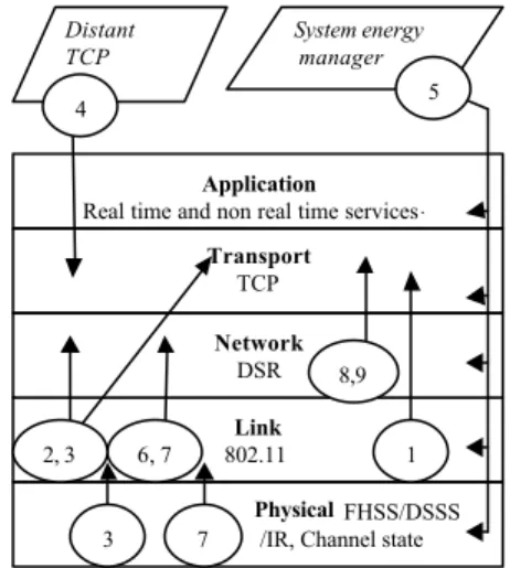
The model given by Notified Events CLAA on the protocol stack, the system energy manager and a distant TCP can be represented as follows. Note that the number represents the CLAA given in legend, the circle symbol shows the CLAA source layer and then the arrow materialises the CLAA destination layer. Here, the number 5 shows that if the energy level reaches a crucial threshold, the system energy manager sends this information to all the layers.
Application
Real time and non real time services .
Transport
TCP
Link
802.11
Physical FHSS/DSSS
/IR, Channel state
Network DSR 8,9 6, 7 System energy manager Distant TCP 4 7 3 2, 3 1 5
Figure 1 : interaction model of NE CLAA Legend :
1. Jitter of sent packets NE 2. Retransmission avoidance NE 3. Acknowledgement NE 4. Explicit congestion NE 5. Significant energy drop NE 6. Packet salvaging NE 7. Received signal power NE
8. Sending jitter due to Route error NE 9. Sending jitter due to Route modification NE 2) Exported states CLAA case
The model given by Exported States CLAA on the protocol stack, the environment subsystem and the system energy manager is as follows. In this model, according to our CLAA census step, the DSR protocol uses only the battery level variable regularly updates by the system energy manager. Here, the number represents the CLAA given in legend, the circle symbol contains CLAA list concerned by the arrow, the arrow indicates the use or the update of variables from or towards environment subsystem. For example, in number 1, the 802.11 link layer updates the packet loss ratio variable that is use by TCP and application independently of other CLAA in the list.
Legend :
1. Packet loss ratio Exported states /using
2. SNR (Signal to Noise Ratio) Exported states/using 3. RSS (Received Signal Strength) Exported states/using 4. BER (Bit Rate Error) Exported states/using
5. Energy level Exported states/using Application
Real time, non real time services .
Transport
TCP
Link
802.11
Physical FHSS/DSSS /IR, Channel state
Network DSR Environment subsystem 1 1, 2, 3, 4, 5 5 1, 2, 3, 4, 5 2, 3, 4, 5 System Energy Manager 5 2, 3, 4
Figure 2 : interaction model of Exported states CLAA 3) Available services CLAA case
By the same deducing mechanism of the interaction model, the model given by Available Services CLAA on the protocol stack and the environment subsystem is as follows. From or towards environment subsystem, the number, the arrows and the circle symbol have the same Exported states CLAA case signification. At difference, in the 3 other cases, the double arrows show information exchange between layers (through Interface Subsystem that do not appears for readability reasons). Theses exchanges aim to activate services in appropriate layer.
For example, Applications ask the concerned layer for services activation. When services are activated, environment subsystem is setup. The other layers use activation indicators or active services parameters to adapt their behaviour.
Environment subsystem
Application
Real time and non real time services.
Transport TCP
Network
IP, RSVP/IntServ/DiffServ Link
802.11, FEC/ARQ/VMAC
Physical
FHSS/DSSS/IR, Channel state Network DSR 4, 5 2, 3, 6 4, 5 2, 3, 6 1 1 1, 4, 5
Figure 3 : interaction model of Available services CLAA Legend :
1. VMAC service 2. IntServ service 3. DiffServ service 4. FEC service
5. ARQ Service 6. RSVP service
6th. Interactions description arrays
The TCP interaction description array that follows indicates the use of each CLAA by the TCP function and the modification of TCP source code that is proposed. We will limit the presentation to this array.
5 Table 3 : Cross-Layer Atomic Actions of TCP
CLAA TCP Function TCP using of CLAA
Jitter of sent packets NE
Sending jitter due to Route error NE Sending jitter due to Route modification NE
If a packet ACK waiting timeout will expire, cancel and reset it (user timeout). Do not retransmit the packet during the new timeout. Do not invoke congestion control mechanism.
Retransmission avoidance NE Freeze the transmissions and retransmissions for the time specified
in the message ⇒ reset all timeouts.
Acknowledgement NE
Transferred data control
Anticipate the new data transmission if DSR protocol ensures that the destination is directly accessible.
Explicit congestion NE Congestion control Invoke the congestion control mechanism.
Significant energy decrease NE Modify the retransmission frequency and/or transmission output.
Packet loss ratio ES SNR, BER ES
Adjust the retransmission frequency according to the high value of these parameters that is established by threshold (channel state).
RSS ES Use the link layer ACK if the threshold of this parameter indicates
that the destination node is directly accessible.
Energy level ES Modify the retransmission frequency and the throughputs according
to high value of this parameter that is established by threshold.
FEC AS
Transferred data control
Cancel the data checksum control mechanism.
ARQ AS Error correction Cancel the data error correction function if the DSR protocol ensures
that the destination is directly accessible.
D. CONCLUSION
Cross layer design is required for mobile ad hoc network to improve their performance contrary to wired networks that are not disabled by the same kind of failures. It is important to do that design in a standard framework to promote the evolution of protocols interaction models by taking into account new interactions or building new models for other protocols. This work aims to create useful formal steps within the seven steps reverse design method that produces conceptual interaction models and efficient interaction description arrays, as it has been shown by the application of the method.
Our on-going work consists of implementing that cross layer interaction models in NS (Network Simulator) environment to estimate the performance gains. The three subsystems (environment, interface, distant), have to be implemented first as additional objects in NS. Then every CLAA of each subsystem have to be placed into the ns source code. It is necessary to identify the existing or the additional fields or instructions or methods of the source protocol, the destination protocol and the subsystem of the CLAA. After each implementation of a CLAA, a simulation will be run to quantify the obtained gain.
E. REFERENCES
[1] S. Shakkottai, T. S. Rappaport, P. C. Karlsson, "Cross-Layer Design for Wireless Network", IEEE Comm. Mag., Oct. 2003. [2] V. T. Raisinghani, A. K. Singh, S. Iyer, Improving TCP
performance over Mobile Wireless Environments using Cross Layer Feedback , Personal Wireless Communications, 2002 IEEE International Conference on , 15-17 Dec. 2002, p81 85.
[3] M. Conti, G. Maselli, G. Turi, S. Giordano, Cross Layering in Mobile Ad hoc Network Design , IEEE Computer society Magazine, February 2004.
[4] Q. Wang, M. A. Abu- Rgheff,, M. A., Cross Layer Signalling for Next Generation Wireless Systems , IEEE WCNC 2003, Volume: 2 , 16-20 Mar 2003 p1084-1089 vol.2.
[5] W. Li, Z. Bao yu, Study on Cross Layer Design and Power Conservation in Ad hoc Network , IEEE PDCAT'2003, 27-29 Aug. 2003 Pages:324 328.
[6] K. Ramakrishnan, S. Floyd, D. Black. « The Addition of Explicit Congestion Notification (ECN) to IP. » RFC3168 September 2001.
[7] J. G. Jetcheva, Y. Hu, D. Johnson, D. Maltz, The Dynamic Source Routing Protocol for Mobile Ad hoc Networks (DSR) , Internet Draft, IETF MANET working group, Nov 2001 [8] D. B. Johnson, D. A. Maltz, Dynamic Source Routing in Ad
hoc Wireless Networks , Mars 1998 http://www.monarch.cs.cmu..edu/monarch -papers/
[9] T. Demir, Simulation of Ad hoc Networks with DSR Protocol , May2001. http://netlab.boun.edu.tr/papers/Iscis2001-DSR-TamerDEMIR+.pdf
[10] The Dynamic Source Routing Protocol for Mobile Ad hoc
Networks (DSR) , 21 february 2002,
www.ietf.org/proceedings/02mar/I-D/draft-ietf-manet-dsr-07.txt [11] P. Almquist « Type of Service in the Internet Protocol
Suite. ». RFC 1349, July 1992, www.ietf.org.
[12] Y. Bernet et al., A framework for Integrated Services Operation over DiffServ Networks , RFC 2998, Nov. 2000. [13] M. Luby et al., The use of Forward Error Correction (FEC)
in Reliable Multicast , RFC 3453, December 2002.
[14] G. Fairhurst, L. Wood, Advice to link designers on link Automatic Repeat reQuest (ARQ) , RFC 3366, August 2002 [15] S. Dawkins et al., End-to-End Performance Implications
of Links with Errors , RFC 3155, August 2001
[16] A. Veres, A.T. Campbell, M. Barry, and L.H. Sun, "Supporting service differenciation in wireless packet networks using distributed control", IEEE JSAC, Vol. 19, No 10, pp. 2094-2104, October 2001.
[17] R. G. Gallager, Energy limited channels : coding, Multi access, and Spread Spectrum , 1998 Conf. Info. Sci Sys. Mar 98 [18] Y. Min-hua, L. Yu, Z. Hui-min, The IP Handoff between
Hybrid Networks , IEEE PIMRC, Sept. 2002, Vol.1, pp265-269 [19] H. Balakrishna, R. Katz, Explicit Loss Notification and
Wireless Web Performance , IEEE Globecom, Sydney, Nov 98. [20] C. Mazel, "évaluation des performances par simulations application aux canaux de signalisation de systèmes radio téléphoniques", PhD. INP Grenoble, June 1988 (in French).