HAL Id: hal-00998755
https://hal-enac.archives-ouvertes.fr/hal-00998755
Submitted on 2 Jun 2014
HAL is a multi-disciplinary open access
archive for the deposit and dissemination of
sci-entific research documents, whether they are
pub-lished or not. The documents may come from
teaching and research institutions in France or
abroad, or from public or private research centers.
L’archive ouverte pluridisciplinaire HAL, est
destinée au dépôt et à la diffusion de documents
scientifiques de niveau recherche, publiés ou non,
émanant des établissements d’enseignement et de
recherche français ou étrangers, des laboratoires
publics ou privés.
A Feedback Linearizing Controller for Relative Guidance
Between Commercial Aircraft
Thierry Miquel, Felix Mora-Camino, Karim Achaibou
To cite this version:
Thierry Miquel, Felix Mora-Camino, Karim Achaibou. A Feedback Linearizing Controller for Relative
Guidance Between Commercial Aircraft. AIAA GNC 2003, AIAA Guidance, Navigation and Control
Conference, Aug 2003, Austin, United States. pp xxxx, �10.2514/6.2003-5410�. �hal-00998755�
A merican Institute of Aeronautics and Astronautics 1
A
FEEDBACK LINEARIZING CONTROLLER FOR RELATIVE
GUIDANCE BETWEEN COMMERCIAL AIRCRAFT
Thierry MIQUEL*, Félix MORA-CAMINO†, KarimACHAIBOU‡
* LAAS duCNRS AND CENTRE D’ETUDES DE LA NAVIGAT ION AERIENNE, TOULOUSE, FRANCE †
LAAS duCNRS AND ECOLE NATIONALE DE L’AVIATION CIVILE, TOULOUSE, FRANCE ‡
LAAS duCNRS, TOULOUSE, FRANCE
EMAIL : [email protected], [email protected], [email protected]
A
BSTRACT
During the last few years, several concepts concerning the delegation to commercial aircraft flight crew of some tasks currently performed by the air traffic controllers have emerged [3]. Among these new ideas, relative guidance has appeared to be of some interest to contribute to the enhancement of air traffic capacity [1] though it rises hard technical challenges. Indeed, this kind of maneuver appears difficult to perform manually, and may induce an excessive increase of the flight crew workload, thus requiring a new on-board automated function, as suggested in [7]. This paper investigates the design of an autopilot mode dedicated to the trailing aircraft for merging and maintaining station keeping behind a leading aircraft. The investigated approach is based on feedback linearization control. We use a new form of relative position error which results in a singularity free stabilizing controller. Moreover, we take explicitly into account the separation between the two aircraft in order to safely manage the maneuver. Some properties of such a controller are also discussed on the basis of a case study including wind.
I
NTRODUCTION
The anticipat ed traffic increase in air traffic encourages the design of new strategies to increase air traffic control capacity significantly while at the same time enhancing safety and flight efficiency. So as to meet this challenge, new concepts such as the delegat ion to the flight crew of some tasks presently performed by air traffic controllers have emerged during the last few years [1].
A subset of this delegation concept is related to relative guidance of aircraft. This concept is supported by the European air traffic control
agency. Indeed the objective of the ‘Enhanced Sequencing and merging operations’, which is one of the applications described in [3], is to redistribute tasks related to sequencing and merging traffic between the controllers and the flight crews. In en-route airspace and terminal area in a radar environment, the controller will be provided with a new set of instructions directing, for example, the flight crews to establish and to maintain a given time or distance from a designated aircraft.
The main challenge for the aircraft relative guidance concept is to enhance air traffic capacity by decreasing air traffic controller workload while at the same time preventing flight crew workload increase. To achieve these goals, new automated functions onboard aircraft must be developed; indeed, nowadays no automatic control mode is available on -board civil aircraft to perform this task.
Recent studies have investigated related problems for Unmanned Air Vehicles (UAV) and military aircraft. In [4] and [10], the control system was designed on a linearized model, whereas in [8] the proposed feedback linearizing control law exhibits a singular point when the desired relative position is zero which may result in infinitely large inputs. On the other hand, research for civil aircraft in this area is in its initial stage: in [1] station keeping is performed manually by the flight deck, whereas in [6] and [11] the authors consider a proportional, integral, and derivative (PID) control to control longitudinal station keeping. But very few papers concentrates on the automatic control of the merging maneuver before maintaining the desired position behind the leading aircraft. Indeed, the merging maneuver exhibits large nonlinearities which can not be handled by linearization. In [9], two approaches based on nonlinear control are presented: the first one is based on feedback linearizing control, whereas the second one is based
AIAA Guidance, Navigation, and Control Conference and Exhibit
1111 - 14 August 2003, Austin, Texas
AIAA 2003-5410
A merican Institute of Aeronautics and Astronautics 2
on optimal control, but for both of them the separation between the two aircraft has not been taken explicitly into account during the design process. This may result in a loss of separation between the two aircraft during the merging maneuver.
In this context, this paper focuses on the design of a nonlinear controller which enable an aircraft to perform merging maneuvers and to maintain station keeping behind a designated aircraft. The investigated approach is based on feedback linearizing control. Such a control is applied to a new expression of relative position error. The interest of this new approach is that it results in a singularity free stabilizing controller. Moreover, it takes explicitly into account the separation between the two aircraft to safely manage the maneuver. The relative guidance controller is confined in the horizontal plane. It provides reference values to the airspeed hold and heading hold autopilots. As others decoupled autopilot functions are available for the motion in the vertical plane, the flight crew remains free to manoeuvre in the vertical plane in case of unexpected situations.
The paper is organized as follows: in the preliminary section, reference frame and aircraft model are introduced. This leads to the nonlinear state space representation which is used in this paper. The subsequent section presents the design of the feedback linearizing controller. Then, some properties of such a controller are also discussed on the basis of a case study including wind. Finally, conclusions are raised.
P
RELIMINARIES
R
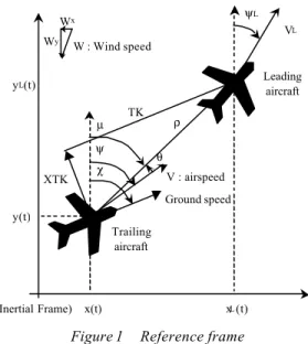
EFERENCE FRAMEIn the following, the along track distance, denoted TK, is aligned with the trailing aircraft ground speed vector, whereas the cross track distance, denoted XTK, is the right handed positive distance from the trailing to the leading aircraft. The heading angle of the trailing aircraft is denoted by ψ, its airspeed by V. Subscript L is added for all variables related to the leading aircraft. Since wind is considered is this paper, the track angle of the trailing aircraft is denoted by χ.
Assuming that the earth is flat and non-rotating, it may be considered as an inertial frame. The track angle χ is the direction followed by the aircraft with respect to this inertial frame, whereas the heading angle ψ is the direction followed by the aircraft with respect to the air. When there is no wind (i.e. Wx=Wy=0), those angles are equal.
x(t) Leading aircraft XTK TK Trailing aircraft ψL y(t) yL(t) xL(t) VL V : airspeed ψ ρ θ µ χ W : Wind speed Ground speed (Inertial Frame) Wx Wy
Figure 1 Reference frame
From Figure 1, the inertial position dynamics of the trailing aircraft are given by:
( )
( )
+
⋅
=
+
⋅
=
y xW
V
y
W
V
x
ψ
ψ
cos
sin
&
&
( 1)Where {Wx, Wy} are the wind components
expressed in the inertial frame, and γ the flight path angle of the aircraft.
Denoting by ψw the wind direction and W its
velocity, and taking into account that the wind direction is the direction from where the wind is blowing (so ψW is zero if the wind is blowing from
the North), the following relation holds:
(
)
(
)
−
⋅
=
−
⋅
=
π
ψ
π
ψ
w y w xW
W
W
W
cos
sin
(2 )A
IRCRAFT DYNAMICSThe trailing aircraft is sup posed to fly in a fully coordinated fashion, i.e. the side-slip angle is always zero (airspeed and fuselage have the same direction).
Furthermore it is assumed that the following two decoupled autopilot functions are available onboard the trailing aircraft. These decoupled functions assume coordination between throttle, aileron and rudder, as in many modern jets.
• The airspeed hold autopilot controls the
conventional airspeed V without affecting the aircraft’s altitude. Denoting by Vc the controlled
A merican Institute of Aeronautics and Astronautics 3
a first order system for the purpose of control design: V c
V
V
V
τ
−
=
&
(3 )• The heading hold autopilot controls the
heading ψ without affecting the aircraft’s airspeed. Heading is assumed to be controlled by the bank angle ϕ. For small bank angle and loading factors, the following relation between heading rate and bank angle holds, where g is the acceleration of gravity, ϕ the bank angle and V the actual airspeed:
V
g
ϕ
ψ
&
=
⋅
(4 )Denoting by ϕc the controlled bank angle, the bank
angle dynamics may be modeled as a first order for the purpose of control design:
ϕ
τ
ϕ
ϕ
ϕ
&
=
c−
(5 )These first-order models for airspeed and bank angle dynamics are usually considered as good models for inner loops flight dynamics [10].
R
ELATIVE POSITION KIN EMATICSIn the following, ρ denotes the (horizontal) range between the leading and the trailing aircraft, and µ the relative bearing between those aircrafts. From
Figure 1, they are related to the inertial positions:
( )
( )
⋅
−
=
⋅
−
=
µ
ρ
µ
ρ
cos
sin
L Ly
y
x
x
(6 )Range and relative bearing are of direct interest for the achievement of safe relative guidance. In
addition, they could be derived from the TCAS1
surveillance or from future Automatic Dependent Surveillance Broadca st (ADS-B) systems [2]. Taking into account ( 1) and assuming the same
wind for the two aircraft, the time derivative of
(6 ) leads to:
(
)
(
)
(
)
(
)
−
−
−
=
−
−
−
=
µ
ψ
µ
ψ
µ
ρ
µ
ψ
µ
ψ
ρ
sin
sin
cos
cos
V
V
V
V
L L L L&
&
(7 )Conversely, range and relative bearing can be derived from to the along track distance TK and the cross track distance XTK by (see Figure 1):
1
Traffic Collision Avoidance System
+ = + = TK XTK arctg XTK TK χ µ ρ 2 2 (8 )
The preceding relationships are useful to translate the objectives manipulated by air traffic controller and pilots (i.e. merge 5 NM behind, 1 NM left) into variables manipulated by the controller.
S
TATE SPACE REPRESENTATIONGathering (3 ), (4 ) and (7 ) leads to the following state space representation of the relative guidance kinematics, where u denotes the control vector and x the state vector:
( ) ( )
[
]
[
]
=
=
+
=
T c TV
u
V
x
u
x
g
x
f
x
ϕ
ψ
µ
ρ
&
(9 )This state space representation declares exogenous the heading ψL and the velocity VL of the leading
aircraft. Indeed, those variables can be made available thanks to air/air data communications. The dynamics (5 ) of the controlled bank angle ϕc
are not taken into account since they are much faster than the relative position dynamics; nevertheless, they are taken into account during simulation s.
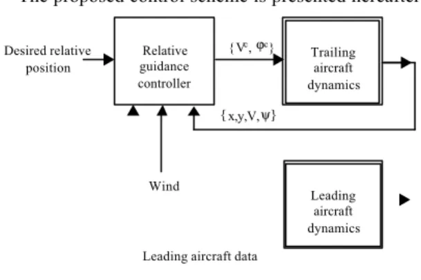
The proposed control scheme is presented hereafter:
Leading aircraft data
{x,y,V,ψ} Desired relative position { Vc, ϕc} Trailing aircraft dynamics Leading aircraft dynamics Relative guidance controller Wind
Figure 2 Block diagram of the relative guidance control system
The purpose of the next section is to design the relative guidance controller so that the controlled variables Vc and ϕc allows the trailing aircraft to
reach the desired position relatively to the leading aircraft.
A merican Institute of Aeronautics and Astronautics 4
R
ELATIVE GUIDANCE CONTROLLER
DESIGN
R
ELATIVE POSITION ERRO RIn this section, we derive a new form of the relative position error which takes explicitly into account the separation between the two aircraft in order to safely manage the maneuver. Moreover, it results in a singularity free stabilizing controller.
The relative position error, or output vector, is chosen as follows:
( )
⋅
=
=
∫
µ µρ
µ
ρ
0d
x
h
y
(10 )From a practical point of view,
ρ
&
is the convergence velocity andρ
µ
&
the normal relative velocity.The first derivative of (10 ) leads to (7 ), whereas the second derivative leads to:
( ) ( )
x
x
u
y
=
∆
+
∆
⋅
+
=
ρ
µ
ρ
µ
0ρ
&
&
&
&
&
&
&
&
(11 )( )
(
)
(
)
(
)
(
)
(
)
(
)
(
)
(
)
−
−
−
−
−
−
−
−
−
−
−
−
−
−
−
−
−
−
−
−
−
−
−
−
−
−
+
−
=
∆
µ
ψ
µ
ψ
µ
τ
µ
ψ
µ
ψ
µ
ψ
µ
τ
µ
ψ
cos
cos
/
sin
sin
sin
/
cos
0V
V
V
V
V
V
x
L L V L L V&
&
(12 )( )
(
(
)
)
(
(
)
)
− ⋅ − − − − ⋅ − − = ∆ µ ψ τ µ ψ µ ψ τ µ ψ cos / sin sin / cos g g x V V (13 )F
EEDBACK LINEARIZING CONTROLThe feedback linearizing technique [5] consists in computing a control law that compensates the nonlinearities of the system to enforce linear dynamics to its outputs. A relative degree is determined from the affine representation for each output variable : this relative degree fixes the order which can be assigned to the output dynamics. As the rank of the matrix ∆(x) defined in (13 ) is always 2 and presents no singularity in the state space, there is no inner dynamic. So, it results in a singularity free stabilizing controller and the output dynamics can be chosen without damage for the overall stability of the system. Inverting (13 ) leads to the following general non linear control law:
( )
x(
y( )
x)
( )
x y l( )
xu=∆ − &&−∆ =∆ −1&&+
0 1 (14 )
( )
(
(
)
)
(
(
)
)
−
−
−
−
−
−
−
=
∆
−g
g
x
V V/
cos
/
sin
sin
cos
1µ
ψ
µ
ψ
µ
ψ
τ
µ
ψ
τ
(15 )( )
[
[
(
(
)
)
(
(
(
(
)
)
]
)
)
]
−
+
−
−
−
−
−
+
=
g
V
V
V
V
V
x
l
L L L L V/
2
cos
cos
2
sin
sin
µ
ψ
ψ
ψ
µ
µ
ψ
ψ
ψ
µ
τ
&
&
(16 )For the derivation of the feedback linearizing controller, let us select the following dynamics of the output vector:
(
)
(
)
−
−
−
−
−
−
=
+
=
d dw
w
w
w
y
µ
µ
µ
ρ
ξ
ρ
ρ
ρ
ξ
µ
ρ
µ
ρ
ρ
µ µ µ ρ ρ ρ 2 22
2
&
&
&
&
&
&
&
&
&
&
(17 )Where ξρ, wρ, ξµ and wµ are positive numbers, and
ρd and µd respectively the desired range and relative
bearing derived from the desired along track and cross track distances thanks to (8 ).
From a practical point of view, the choice of a faster dynamics for the normal relative velocity compared to the convergence velocity (i.e.
2 2
1
1
µ ρ ρµ
−
ξ
>>
w
−
ξ
w
) allows to neglectρ
&
inthe expression of ρµ&&+ρ&µ&: so, the second equation of (17 ) can be viewed as a way to settle the dynamics of the relative bearing µ, whereas the first equation of (17 ) settles the dynamics of the range ρ.
The control law is then given by inserting (17 ) into (14 ). After that, the inputs (i.e. the controlled bank angle and airspeed) of the relative guidance controller are limited at the follow ing ‘safe’ values:
≤
≤
+
≤
≤
−
max min max maxV
V
V
c cϕ
ϕ
ϕ
(18 )C
ASE STUDY
S
CENARIOIn this section, a scenario is designed in order to evaluate the properties of the control laws previously designed.
The leading aircraft starts at x0 = 0 NM, y0 = 0 NM,
with initial conventional airspeed and heading of 240 kts and 90 degrees respectively. It is supposed to broadcast its data every second.
The controlled bank angle of the leading aircraft is always zero, except between 600 sec and 630 sec
A merican Institute of Aeronautics and Astronautics 5
where the leader changes its heading by about 50 degrees through a 20 degrees controlled bank angle. The controlled conventional airspeed of the leading aircraft is first set at 240 kts for t ≤ 300 sec, then is set to 190 kts.
The trailing aircraft starts at x0 = +8NM, y0 = -8NM,
with initial conventional airspeed and heading of 240 kts and 0 degrees respectively.
The simulation period lasts 15 min (900 sec), and the requested separation for the trailing aircraft remains constant and equal to 5 NM behind the leading aircraft.
The whole maneuver is supposed to take place within a wind of 20 kts blowing from North; furthermore, both aircraft are assumed to fly at FL80.
During the maneuver, the inputs (i.e. the controlled bank angle and airspeed) of the relative guidance controller are limited at the following ‘safe’ values:
≤
≤
+
≤
≤
−
kts
V
kts
c c250
170
.
deg
20
.
deg
20
ϕ
(19 )The time constants τV and τϕ of the airspeed and heading hold autopilot are set to the following values:
=
=
sec
5
sec
40
ϕτ
τ
V (20 )The values of the constants defining the output vector dynamics have been chosen as follows:
=
=
=
=
− −6
.
0
sec
05
.
0
1
sec
05
.
0
1 1 µ µ ρ ρξ
ξ
w
w
(21 )R
ESULTSThe scenario has been constructed such as no control of the trailing aircraft trajectory will result in a minimum range between the two aircraft equals to zero.
The movement of the leading and trailing aircraft in the horizontal plane are shown in Figure 3. The curvature of the trajectory at the beginning of the encounter comes from the saturation of the controlled outputs. It clearly shows the tendency of the controller to ensure separation between the two aircr aft.
Figure 3 Movement of the trailing aircraft in the horizontal plane (axes in NM)
The evolution in the actual range between the leading and the trailing aircraft is shown in Figure
4. As intended, the slant range tends to the desired 5
NM. Furthermore, the controller tends to stick to that desired value despite the changes in leading aircraft heading and airspeed. This is an encouraging behaviour from the robustness point of view.
Figure 4 Actual range (in NM) between the leading and the trailing aircraft as a function of time (in sec)
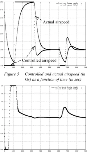
Figure 5 and Figure 6 show respectively the
evolution of controlled and actual conventional airspeed and bank angle:
Trailing aircraft Wind
Leading aircraft
A merican Institute of Aeronautics and Astronautics 6
Figure 5 Controlled and actual airspeed (in kts) as a function of time (in sec)
Figure 6 Controlled and actual bank angle (in degrees) as a function of time (in sec)
The last figure shows that neglecting the bank angle dynamics during the design of the controller does not have a significant impact: indeed, it just slightly delays the actual bank angle.
Finally, the load factor as a function of time in represented in the following figure: it shows that the maneuver remains quite comfortable for passengers:
Figure 7 Load factor as a function of time (in sec)
Note : The load factor has been computed as follows: ⋅ = = + = ⋅ = g V n g V n n n dt V d g n y x y x ψ& & r 2 2 1 (22 )
C
ONCLUSION
In this paper, the design of a controller to perform relative guidance maneuver from a designated aircraft has been considered.
The proposed approach relies on feedback linearizing control. The proposed design is based on a new form of relative position error which results in a singularity free stabilizing controller. Moreover, we take explicitly into account the separation between the two aircraft in order to safely manage the maneuver.
The paper has focused on a separation objective expressed in terms of distance. Nevertheless, some simulations have shown the interest to express the separation objective in terms of delay [1]. So, provided that the delay criteria is translated into a separation objective, the proposed control design approach can be easily extended to this case. This ap proach appears quite interesting. It deserves further studies, especially on the robustness of such a controller to noisy data from the leading aircraft and to gust of wind. In addition, a special attention will be given on neglected dynamics.
Actual airspeed
A merican Institute of Aeronautics and Astronautics 7
R
EFERENCES
[1] Agelii M., Olausson C., Flight deck
simulations of station keeping , ATM 2001
R&D seminar, Santa Fe, paper no. 17
[2] Barhydt R., Warren A., Development of
Intent Information Changes to Revised Minimum Aviation System Performance Standards for Automatic Dependent Surveillance Broadcast (RTCA/DO-242A),
NASA/TM -2002, may 2002
[3] European commission & Eurocontrol,
CARA/ASAS Activity 5 description of a first package of GS/AS applications, version 2.2,
september 2002
[4] Giulietti F., Pollini L., Innocenti M.,
Autonomous Formation Flight, IEEE
Control Systems Magazine, December 2000
[5] Isidori A., Nonlinear control systems,
Springer-Verlag, 1989
[6] Ivanescu D., Hoffman E., Zeghal K., Impact
of ADS-B link characteristics on the performances of in-trail following aircraft,
AIAA Guidance, Navigation and Control Conference, Monterey, USA, August 2002 [7] Jenkinson L.R., Caves R. E., Rhodes D. P.,
Automatic formation flight: a preliminary investigation into the application to civil operations, Loughborough university of
technology, England, 1995
[8] Li S.M., Boskovic J.D., Mehra R.K.,
Globally stable automatic formation flight control in two dimensions, AIAA Guidance,
Navigation and Control Conference. Montreal, August 2001, Paper No. 2001-4046
[9] Miquel T., Mora-Camino F., Relative
guidance of aircraft: analysis and comparison of two control approaches,
World Aviation Congress, November 2002, Paper No. 02WAC-55
[10] Pachter M., D’Azzo J.J., Dargan J.L.,
Automatic formation flight control, Journal
of guidance, control and dynamics, vol. 17, pp 1380-1383, 1994
[11] Vanken P., Hoffman E., Zeghal K., Influence
of speed and altitude profile on the dynamics of in-trail following aircraft ,