UNIVERSITÉ DE MONTRÉAL
SURFACE PLASMON RESONANCE SENSOR INTERROGATION WITH
CLADDING MODES EXCITED BY TILTED FIBER BRAGG GRATING
MOHAMAD DIAA BAIAD
DÉPARTEMENT DE GÉNIE ÉLECTRIQUE ÉCOLE POLYTECHNIQUE DE MONTRÉAL
THÈSE PRÉSENTÉE EN VUE DE L’OBTENTION DU DIPLÔME DE PHILOSOPHIAE DOCTOR
(GÉNIE ÉLECTRIQUE) DÉCEMBRE 2014
UNIVERSITÉ DE MONTRÉAL
ÉCOLE POLYTECHNIQUE DE MONTRÉAL
Cette thèse intitulée :
SURFACE PLASMON RESONANCE SENSOR INTERROGATION WITH
CLADDING MODES EXCITED BY TILTED FIBER BRAGG GRATING
présentée par : BAIAD Mohamad Diaa
en vue de l’obtention du diplôme de : Philosophiae Doctor a été dûment acceptée par le jury d’examen constitué de : M. LESAGE Frédéric, Ph. D., président
M. KASHYAP Raman, Ph. D., membre et directeur de recherche M. LAURIN Jean-Jacques, Ph. D., membre
DEDICATION
dedicated to my family, for all of the love, support, and encouragement in memory of my grandfather Jamal Habes
ACKNOWLEDGEMENTS
I would like to use these few lines to express my gratitude to my supervisor, colleagues and friends who supported me on this thesis.
First of all I'd like to thank my supervisor and research director Prof. Raman Kashyap who warmly welcomed me in his research team. He was really what I would call a great supervisor. Giving his time to define and refine my project, sharing his ideas and listening to mine. Prof. Kashyap has always believed in my potential, supported me throughout this project from the beginning, which was really touching.
I would like to especially acknowledge Prof. Caroline Boudoux who I have worked and collaborated with. She has been a constant support during the later years of my PhD. Special thanks for the invaluable help.
Furthermore, I would like to express my upmost appreciation to the following colleagues for their help and support: Mathieu Gagné, Victor Lambin Iezzi, Jérôme Lapointe, Ameneh Bostani, Elton Soares de Lima Filho, and Sébastien Loranger. When I started, it was a hard job to get to know so many new colleagues, now it will be quite hard to think about leaving such kind people. Also in particular thanks to my colleague and friend Mamoun Wahbeh for supporting me during my PhD and my personal life. I will never forget how much he did for me!
RÉSUMÉ
Le but de ce projet est de developer de nouvelles configurations de capteurs à résonance de plasmons de surface basés sur les réseaux de Bragg. Il se concentre sur l’étude de quatre configurations novatrices de capteurs à résonances de plasmons et de leur application en mesure d’indice de réfraction environnant.
Premièrement, une nouvelle approche de mesure d’indice de réfraction utilisant un coupleur à double gaine et un réseau de Bragg pour capturer les modes de gaine en réflexion est démontrée. Le spectre optique ainsi que la puissance des modes de gaines sont obtenus à travers l’utilisation d’un coupleur à fibre à double gaine conçu sur mesure et connecté à un réseau de Bragg à haute réflectivité écrit dans une fibre photosensible standard légèrement inclinée et gravée de façon à la coupler au diamètre intérieur de la fibre à double gaine. Ce dispositif est capable de capturer les modes de gaines autant d’ordres inférieurs que supérieurs en réflexion de manière simple et efficace. Il devient alors possible de déterminer l’indice de réfraction environnant avec une extrême sensibilité à partir d’une perte de puissance mesurée de ≈ 91% de la puissance initiale permettant d’obtenir une résolution de 1.4333×10⁻⁵ unités d’indice de réfraction (UIR) entre 1.37
et 1.45. Le dispositif permet donc une large bande d’opération entre 1.30 et 1.45 UIR qui offre la possibilité de discriminer chacun des modes de gaine capturés. L’approche proposée peut être adaptée à plusieurs autres types de capteurs de courbure, température, indice de réfraction et d’onde évanescente.
Deuxièmement, une nouvelle approche de capteur à résonance de plasmons de surface à fibre utilisant la configuration de coupleur à double gaine décrite précédemment ainsi qu’un réseau de Bragg incliné et recouvert d’or est démontrée. Cette nouvelle approche d’interrogation basée sur le spectre de réflexion offre une amélioration de la bande d’opération du dispositif en comparaison aux techniques préexistantes. Le dispositif permet la détection de résonances de plasmons de surfaces dans le spectre de réflexion et de transmission, permettant aisément une comparaison avec les techniques standards préexistantes qui utilisent le spectre de transmission. Le capteur possède aussi une large bande d’opération allant de 1.335 à 1.432 UIR et une sensibilité de 510.5 nm/UIR. Le capteur démontre une forte dépendance à l’état de polarisation du mode de cœur qui peut être utilisé pour activer ou désactiver la résonance plasmonique.
La troisième approche est un capteur à plusieurs canaux en série excités à l’aide de réseaux de Bragg inclinés inscrits dans une fibre avec une déposition d’or et de chrome. Les canaux sont inscrits dans une seule fibre optique et chacun possède une bande de longueur d’onde d’opération différente, une inclinaison du réseau de Bragg différente, et donc un intervalle d’indice de réfraction qui lui est propre. Ce système, agissant comme un multiplexeur dans un une seule fibre optique ayant un certain nombre de réseaux de Bragg inclinés, est démontré pour la première fois. La polarisation de chaque canal, qui est basé sur l’orientation de l’inclinaison de chaque réseau de Bragg incliné, peut être utilisé pour activer ou désactiver chaque capteur plasmonique. Cette approche offre une bande d’opération de 1.40 à 1.44 UIR et une sensibilité d’environ 500 nm/UIR.
La quatrième approche fait appel à la déposition d’une couche de silicium et est aussi une configuration à multiples canaux étant chacun associés à un type de fibre différent. L’utilisation couche diélectrique à indice de réfraction élevée de silicium est démontrée et caractérisée pour la première fois pour un tel dispositif. Chaque canal démontre un intervalle d’opération unique. La couche de silicium est utilisée pour ajuster la bande d’opération d’indice de réfraction à une valeur plus basse. Ce système permet une opération allant de 1.30 à 1.435 UIR, ce qui est le plus large intervalle démontré à ce jour pour un tel dispositif. L’ajout d’une couche de silicium améliore la sensibilité du capteur à ~700 nm/UIR and démontre une plus forte dépendance en polarisation. La flexibilité et la facilité d’utilisation de l’approche proposée peut être adaptée à plusieurs configurations de capteurs plasmoniques.
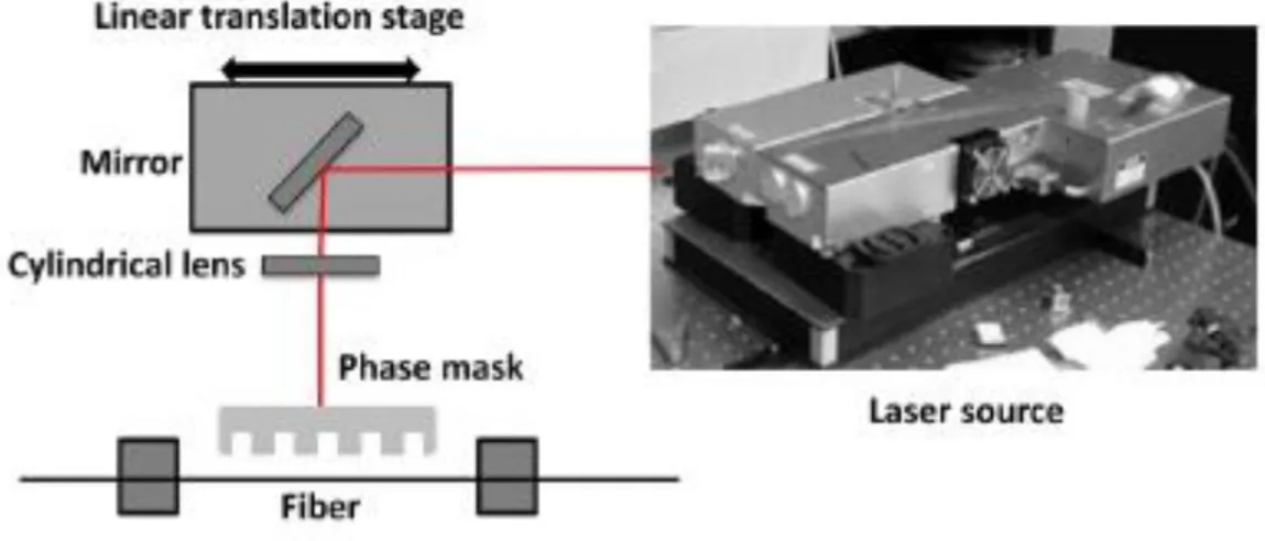
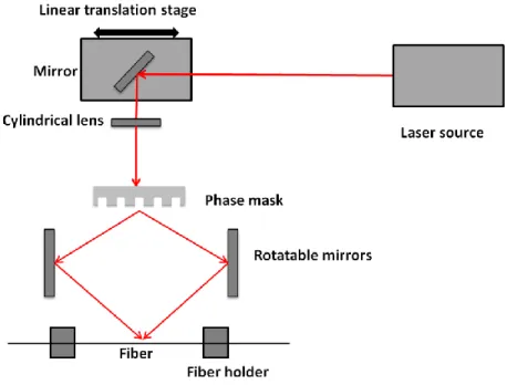
Les réseaux de Bragg proposés au cours de ce projet ont été écrits à l’aide de différentes techniques. Une nouvelle source laser pulsée de 224 nm offrant une puissance maximale de 280 mW a été utilisée pour la fabrication de réseaux de Bragg conjointement à l’utilisation d’un montage de balayage de masque de phase. Les réseaux de Bragg inclinées ont été obtenus à l’aide d’une source laser pulsée analogue de 213 nm utilisée dans un second montage de balayage de masque de phase. Le laser de 213 nm produit des impulsions de 7 ns avec une énergie de 10 μJ à un taux de repetitions allant de 0.1 à 30 kHz et avec une puissance moyenne maximale de 130 mW. En utilisant un interféromètre, la longueur d’onde de Bragg peut être choisie indépendamment de la longueur d’onde du laser UV en changeant l’angle des miroirs de l’interféromètre. Pour fabriquer des réseaux de Bragg inclinés, la monture de la fibre optique est tournée relativement à l’axe d’orientation de la fibre.
Les configurations proposées visent à améliorer les performances des capteurs à résonance de plasmons de surface des points de vue de la miniaturisation, de la sensibilité et du multiplexage, des ajouts significatifs à la technologie actuelle des capteurs plasmoniques utilisant des réseaux de Bragg inclinés.
ABSTRACT
The objective of this Thesis is to develop novel schemes in surface Plasmon resonance (SPR) sensing with Bragg gratings. The thesis focuses on research studies on the sensing characteristics of four novel configurations of SPR and surrounding refractive indices (SRI) sensors.
Firstly, a novel SRI measurement scheme has been demonstrated using a double-clad fiber coupler (DCFC) and a fiber Bragg grating (FBG) to capture cladding modes in reflection. The optical spectra and power in the cladding modes are obtained through the use of a specially designed DCFC spliced to a highly reflective FBG written into slightly cladding-etched standard photosensitive single mode fiber to match the diameter to the inner cladding of the DCFC. The device is capable of capturing low and high order backward propagating cladding modes simply and efficiently. The device is capable of measuring the SRI with an extremely high sensitivity with a total power drop by ≈ 91% of its initial value and a resolution of 1.433×10⁻⁵ RIU between 1.37
and 1.45 RIU. The device provides a large SRI operating range from 1.30 to 1.45 RIU with sufficient discrimination for all individual captured cladding modes. The proposed scheme can be adapted to many different types of bend, temperature, refractive index and other evanescent wave based sensors.
Secondly, a novel optical fiber SPR sensor scheme is demonstrated using reflected guided cladding modes captured by the above mentioned DCFC, and excited in a gold-coated fiber with a tilted Bragg grating (TFBG). This new interrogation approach which is based on the reflection spectrum provides an improvement in the operating range of the device over previous techniques. The device allows detection of SPR in the reflected spectrum and also in the transmitted spectrum as well, making it far easier in comparison with previous standard techniques which use the transmission spectrum. The sensor has a large operating range from 1.335 to 1.432 RIU, and a sensitivity of 510.5 nm/RIU. The device shows strong dependence on the polarization state of the guided core mode which can be used to turn the SPR on or off.
The third scheme is an in-line, multichannel SPR sensor scheme excited with a TFBG inside a chromium and gold-coated fiber. The channels are imprinted in one single optical fiber and each has a different operating wavelength, different TFBG tilt angle, and hence different refractive index operating range. This system, as a multiplexer in a single optical fiber for a number of TFBG-SPR sensors, is demonstrated for the first time. The polarization state of each channel
based on the TFBG orientation can be used to switch each SPR sensor on or off as required. This scheme provides an operating range from 1.40 to 1.44 RIU, and a sensitivity of around 500 nm/RIU.
The fourth scheme is a silicon-coated multi-channel SPR sensor scheme excited with a TFBG where different types of fibers have been used and each represents a single separate channel. The high-index dielectric layer silicon coating is demonstrated and characterized for the first time in such am SPR-TFBG sensor. Each channel shows a unique refractive index operating range. The silicon layer is used to tune the SPR refractive index operating range to lower values. This system provides a refractive index operating range from 1.30 to 1.435 RIU, which to our knowledge, is the largest reported so far of such SPR-TFBG sensors. Adding the silicon layer improves the sensor sensitivity to ~700 nm/RIU and shows stronger polarization dependence. The flexibility and the improved ease of use of the proposed scheme can be adapted to many SPR-TFBG based sensors applications.
The FBGs and the TFBGs proposed in this project have been written by different techniques. A new high-repetition rate 224 nm laser source was used for the FBG fabrication using a scanning phase mask technique with a maximum average writing power of 280 mW at 224 nm. The TFBGs were written using a commercially available 213 nm Q-switched nanosecond Nd:VO4
laser and a newly developed scanned phase-mask-based Talbot interferometer. The 213 nm laser produces pulses of 7 ns with an energy of 10 μJ at a repetition frequency between 0.1 and 30 kHz with a maximum average power of 130 mW. By using the interferometer, the Bragg wavelength can be chosen independently of the UV laser wavelength by changing the mutual angle between the mirrors of the interferometer and the fiber plane. To fabricate tilted gratings with interferometer, the fiber holder is rotated relative to the propagation axis of the fiber.
The proposed configurations aim to improve the performance of SPR biosensors towards miniaturization, better discrimination, increased sensitivity, and multi-analyte sensing which can add significant improvement to existing surface Plasmon resonance sensors using tilted fiber Bragg gratings.
TABLE OF CONTENTS
DEDICATION ... III ACKNOWLEDGEMENTS ... IV RÉSUMÉ ... V ABSTRACT ... VIII TABLE OF CONTENTS ... X LIST OF FIGURES ... XIII LIST OF SYMBOLS AND NOTATIONS ... XVIII LIST OF APPENDICES ... XXCHAPTER 1 INTRODUCTION ... 1
1.1 Overview of the dissertation ... 1
1.2 Literature review ... 1
1.3 Basics of Surface Plasmon Resonance ... 11
1.4 Objectives ... 25
1.4.1 Design step ... 25
1.4.2 Fabrication and implementation step ... 25
1.4.3 Validation step ... 25
1.5 Note on collaborations ... 26
CHAPTER 2 INTRODUCTION TO BRAGG GRATINGS ... 27
2.1 Basic concepts of fiber Bragg gratings ... 28
2.2 Tilted fiber Bragg gratings ... 34
2.3 Fabrication of Bragg gratings ... 37
CHAPTER 3 ARTICLE 1: CAPTURING REFLECTED CLADDING MODES FROM A
FIBER BRAGG GRATING WITH A DOUBLE-CLAD FIBER COUPLER ... 49
3.1 Abstract ... 50
3.2 Introduction ... 50
3.3 Experimental procedure ... 51
3.4 Results and Discussion ... 53
3.5 Conclusion ... 60
CHAPTER 4 ARTICLE 2: SURFACE PLASMON RESONANCE SENSOR INTERROGATION WITH A DOUBLE-CLAD FIBER COUPLER AND CLADDING MODES EXCITED BY A TILTED FIBER BRAGG GRATING ... 61
4.1 Abstract ... 62
4.2 Introduction ... 62
4.3 Experimental procedure ... 63
4.4 Results and Discussion ... 64
4.5 Conclusion ... 70
CHAPTER 5 ARTICLE 3: CONCATENATION OF SURFACE PLASMON RESONANCE SENSORS IN A SINGLE OPTICAL FIBER USING TILTED FIBER BRAGG GRATINGS………...72
5.1 Abstract ... 72
5.2 Introduction ... 73
5.3 Experimental Procedure ... 74
5.4 Results and Discussion ... 75
5.5 Conclusion ... 81
CHAPTER 6 ARTICLE 4: SILICON-COATED MULTI-CHANNEL SURFACE PLASMON RESONANCE SENSORS USING TILTED FIBER BRAGG GRATINGS... 82
6.2 Introduction ... 83
6.3 Experimental Procedure ... 84
6.4 Results and Discussion ... 86
6.5 Conclusion ... 93
CHAPTER 7 GENERAL DISCUSSION ... 95
CHAPTER 8 CONCLUSION AND FUTURE WORK ... 101
8.1 Direction for future work ... 102
REFERENCES ... 104
APPENDIX A: PHOTOSENSITIVITY ... 111
APPENDIX B : COUPLED MODE THEORY ... 114
APPENDIX C: LIST OF PUBLICATION RELATED TO THE DISSERTATION ... 119
List of figures
Fig. 1. (a) prism-coupling configuration and (b) resonance dip and its shift in the reflected light
spectrum. ... 2
Fig. 2. Fiber-SPR with polished and metal-coated tip. ... 3
Fig. 3. Side – polished optical fiber SPR sensor. ... 4
Fig. 4. Silicon-coated metalized Multi-mode optical fiber without using Bragg gratings [21]. ... 4
Fig. 5. Reflection and Transmission spectra using Bragg grating in optical fiber ... 5
Fig. 6. Tilted fiber Bragg grating (TFBG) and its transmission spectrum in optical fiber. ... 6
Fig. 7. Transmission spectrum using LPG in optical waveguide ... 6
Fig. 8. SPR-WBG sensor proposed by Ctyroky ... 6
Fig. 9. SPR-cladding modes coupling using tilted fiber Bragg gratings (TFBG). ... 9
Fig. 10. Gold metal layer sandwiched between two infinite dielectric layers. ... 14
Fig. 11. Simulation results of the real component of Hy (top) and imaginary (bottom) profiles of SPR of symmetric mode of silica-gold-silica interface for a film thickness of 40 nm. ... 19
Fig. 12. Simulation of the Hy component profile of SPR anti-symmetric mode of dielectric-gold-dielectric interface for a film thickness of 40 nm. ... 21
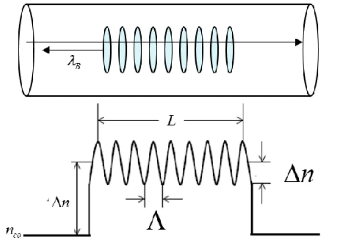
Fig. 13. Ray-optic illustration of core-mode Bragg reflection by a fiber Bragg grating ... 28
Fig. 14. Schematic representing fiber Bragg gratings. ... 29
Fig. 15. Transmission spectrum of fiber Bragg gratings at 1550 nm. ... 34
Fig. 16. Phase matching and wavevectors of TFBG with tilt angle ˂ 45̊. ... 35
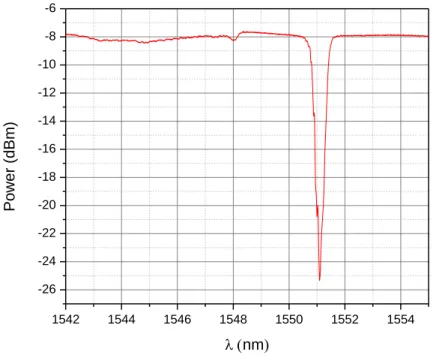
Fig. 17. Transmission Spectrum of 6° TFBG written in photosensitive fiber. ... 37
Fig. 18. Scheme of the phase mask. ... 38
Fig. 19. Setup of the phase mask technique Bragg gratings fabrication. ... 39
Fig. 20. Phase mask used for FBG fabrication ... 39 Fig. 21. Transmission spectrum of a 12 mm FBG written in a fiber with 240 mW 224 nm laser. 40
Fig. 22. Growth of the gratings strength (index modulation) for a 3 mm FBG written on a B/Ge doped for 224 nm from [69]. ... 41 Fig. 23. Scheme of the scanning phase mask interferometer to write Bragg gratings. ... 42 Fig. 24. FBG written the Talbot interferometer when the mirrors are at right angles to the axis of
the fiber and the phase-mask plate in 1060 Flexcore fiber. ... 43 Fig. 25. Rotating the mirrors and tunning the mutual angle to write Bragg gratings at shorter
wavelengths. ... 43 Fig. 26. FBG written in Corning RGB fiber at 617 nm by the Talbot interferometer. ... 44 Fig. 27. Writing TFBGs with the Talbot interferometer and the scanning phase mask technique. ... 45 Fig. 28. TFBG written in a specially fabricated fiber by the scanning phase mask interferometer. ... 46 Fig. 29. Characterizing the metal thickness by surface profilometer (left) on a flat glass slide, and
by SEM (middle), and characterizing the surface smoothness by AFM (right). After the characterization, the optical fiber is coated with the desired metal thickness. ... 47 Fig. 30. Schematic of the proposed device to characterize the reflection spectrum. ... 52 Fig. 31. The transmission and reflection spectra of the proposed scheme before etching of the
DCF. ... 53 Fig. 32. Spectral response of the DCFC core transmission and the inner cladding transmission. 54 Fig. 33. The reflection spectra of the proposed scheme with the fiber diameter decreased by 10,
18 and 20 ± 0.2 µm by wet etching. ... 55 Fig. 34. The reflection (red curve) and the transmission (black curve) spectra of the proposed
device after wet etching by 20 µm. ... 56 Fig. 35. The reflection spectra of the optimised device (20 micron etch) in response to different
SRI. ... 57 Fig.36. Dependence between the number of cladding modes disappear on increasing the SRIs
Fig. 37. Distribution of the reflected power with different SRI. ... 59 Fig. 38. Schematic diagram of the proposed SPR sensor. Light from a broad band source (BBS)
is coupled to a gold-coated tilted fiber Bragg grating (TFBG) through the core of a double-clad fiber coupler (DCFC). Reflected double-cladding modes are collected at branch (2) of the DCFC and characterized by the optical spectrum analyzer (OSA). ... 63 Fig. 39. Transmission of the core mode (black) and reflection of the core and cladding modes
(red) spectra from the gold-coated 6° TFBG when the device is in air. ... 65 Fig. 40. The calculated reflectance with respect to the incidence angle for 4 surrounding
refractive index (SRI) values at 1550 nm. ... 66 Fig. 41. Dependence of the resonant SPR and the cladding modes incident angles on the SRI for
the 4 layers structure. For each SRI data point, two or more cladding modes get affected and match the PM condition. ... 67 Fig. 42. SPR excitation and shift in transmission (black) and in reflection (red) with wavelength
as a function of the surrounding refractive index (SRI) (a) SRI = 1.335 RIU (b) SRI = 1.390 RIU (c) SRI = 1.410 RIU (d) SRI = 1.430 RIU. Arrows indicates the SPR signature.68 Fig. 43. Transmission (top) and reflection (bottom) spectra of two orthogonal linear states in
surrounding refractive index (SRI) =1.370 to turn the SPR on (black) and off (red-offset by 15 dB). ... 69 Fig. 44. Shift of the SPR wavelength as a function of the surrounding refractive index SRI. ... 70 Fig. 45. Schematic diagram of the proposed in-line multiplexed SPR sensor based on three
TFBGs with different tilt angles for the fiber Bragg gratings (TFBG). The output is characterized by the optical spectrum analyzer (OSA). ... 74 Fig. 46. Transmission of the multichannel TFBGs spectra in air from (a) the 4.5° TFBG at core
Bragg wavelength of 1516 nm as channel 1(b) the 6° TFBG at core Bragg wavelength of 1539.5 nm as channel 2 (c) the 4° TFBG at core Bragg wavelength of 1569 nm as channel 3. ... 76
Fig. 47. The transmission spectra of three different TFBGs written with different tilt angles and at different operating wavelengths in series in response to surrounding refractive index (SRI) with no metal coatings. ... 77 Fig. 48. SPR excitation of channels 1 and 2 (top) simutaneously in surrounding refractive index
(SRI) of 1.43 and 1.42, respectively. Channel 3 (bottom) shows SPR excitation independently up to SRI of about 1.44 RIU. Arrows indicates the SPR signatures. ... 79 Fig. 49 Transmission spectra of two TFBG2 & 3 simutaneously with different tilt orientation at
two different orthogonal linear states in SRI of 1.43 to turn the SPR of channel 2 (top) on or channel 3 (bottom) as required. Arrows indicates the SPR signature. ... 80 Fig. 50 Shift of the SPR wavelength as a function of the surrounding refractive index (SRI) of the
three TFBGs coated with 2 nm chromium and 35 nm gold. ... 81 Fig. 51. Schematic diagram of the multichannel TFBG-SPR sensor. Light from a
super-continuum laser source is coupled to the coated tilted fiber Bragg grating (TFBG) through a 2x2 standard coupler. Transmission spectra are characterized at branch (3) and branch (4) by the optical spectrum analyzer (OSA). ... 85 Fig. 52. Transmission spectra of the TFBGs in air from TFBG1 (top) at core Bragg wavelength of
1539.5 nm as channel 1 and TFBG2 (bottom) at core Bragg wavelength of 1584 nm as channel 2. Note that the bottom spectrum has a bandwidth almost 2 that of the top spectrum. ... 86 Fig. 53. Dependence of the calculated resonant SPR incident angles on the SRI for the proposed
device when the TFBG is coated with 2 nm chromium, 35 nm of gold with/without 10 nm silicon layer. ... 88 Fig. 54. SPR excitation of TFBG1 and shift with wavelength as the surrounding refractive index
(SRI) increases (a) when coated with 2 nm chromium, 35 nm gold (b) when coated with 2 nm chromium, 35 nm gold, and 10 nm silicon. Arrows indicates the SPR signature. ... 89 Fig. 55. Transmission spectra of TFBG2 showing the SPR excitation as the SRI increases (a)
when coated with 2 nm chromium, 35 nm gold (b) when coated with 2 nm chromium, 35 nm gold, and 10 nm silicon. Arrows indicates the SPR signature. ... 90
Fig. 56. Polarized transmission spectra of TFBG1 & 2 with different tilt orientation at two different orthogonal linear states (p & s-polarized states) in SRI of 1.395 and 1.310, respectively for TFBG1 & 2 coated with chromium, gold and silicon. Circles indicates the SPR signature. ... 91 Fig. 57. SPR wavelength dependence on the surrounding refractive index (SRI) of the two used
TFBGs coated with 2 nm chromium, 35 nm gold, and with/without 10 nm silicon. The straight lines are the fit to the data points. ... 92 Fig. 58. Zoom on the TFBG2 SPR signatures of transmitted amplitude spectra for p-polarization
modes in SRI of 1.31 RIU when TFBG2 is coated with chromium and gold without silicon (top) and with silicon (bottom). Circles indicates the SPR signature. ... 93
LIST OF SYMBOLS AND NOTATIONS
UV Ultra-violet
SPR Surface Plasmon resonance SPW Surface Plasmon wave SPP Surface Plasmon polariton
LRSPR Long range surface Plasmon resonance SRSPR Short range surface Plasmon resonance LP Linearly polarized
FBG Fiber Bragg grating TFBG Tilted fiber Bragg grating LPG Long period grating SMF Single mode fiber
SMF-28 Single mode fiber (full name Corning® SMF 28™) MMF Multi-mode fiber
FWHM Full-Width Half Maximum CW Continuous Wave
HF Hydrofluoric acid
OSA Optical Spectrum Analyzer PC Polarization Controller DCFC Double-clad fiber coupler DCF Double-clad fiber
SNR Signal-to-Noise Ratio NA Numerical aperture RIU Refractive Index Unit SNR Signal to noise ratio TE Transverse electric TM Transverse magnetic TIR Total internal reflection PM Phase matching
YLF Yttrium lithium fluoride BBC Broadband source
SWS Swept wavelength system OSA Optical spectrum analyzer SOP State of polarization
LIST OF APPENDICES
APPENDIX A: PHOTOSENSITIVITY ... 111 APPENDIX B : COUPLED MODE THEORY ... 114 APPENDIX C: LIST OF PUBLICATION RELATED TO THE DISSERTATION ... 119
CHAPTER 1
INTRODUCTION
1.1 Overview of the dissertation
This dissertation is organized as follows:
Chapter 1 reviews the literature in the field and discusses what has already been demonstrated so far. It shows the limitations of other technologies leading up to what exactly this dissertation is trying to solve. Also, chapter 1 introduces the basics and theory of surface Plasmon resonance (SPR) relevant to the project. In the end of chapter 1, the objectives of the project have been introduced. Chapter 2 presents an introduction to the theory of Bragg gratings. Equations and various techniques of fabrication relevant to the proposed project are presented, described and compared. The theory and the fabrication techniques of TFBGs are highlighted. Furthermore, the process of coating the TFBGs is introduced. Chapter 3 presents the first article presented during the PhD project. The article is on capturing the cladding modes in reflection by using the DCFC. The cladding modes are excited in this project by strong FBG written in a photosensitive fiber. The scheme has been used as refractometer to measure the SRI leading up to the TFBG-SPR sensor presented in chapter 4. Chapter 4 presents the second article based on interrogating the SPR in reflection by capturing the cladding modes by DCFC with TFBG. Chapter 5 introduce an article of distributed SPR sensors by concatenation of multi in-line sensors in a single optical fiber by TFBGs. Chapter 6 presents the fourth article of the dissertation demonstrating the improvement of sensitivity and polarization dependency of silicon and gold coated multi-channel SPR sensors using TFBGs. In Chapter 7, a general discussion on the proposed schemes and their impact on the field of SPR-TFBG sensors is presented. Also, their limitations and the recommendations to overcome them has been discussed. In Chapter 8, the work is concluded and the directions for future work is proposed.
1.2
Literature review
Surface Plasmon are surface electromagnetic excitation waves supported at a metal-dielectric interface having their electric field maxima at the metal-dielectric boundary, decaying exponentially on either side with a small penetration depth. Surface Plasmon resonance (SPR) based biosensors are label-free bio-sensors which have significant importance in applications
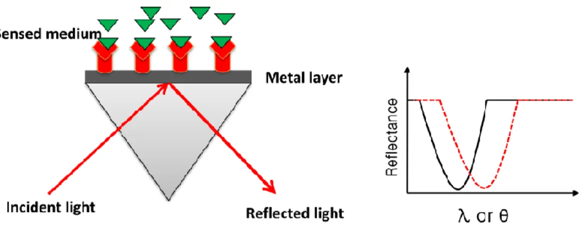
such as medical diagnosis and environmental assessment. They are increasingly popular in biological applications for the measurements of bio-molecular interactions in real-time [1]–[3]. When Wood in 1902 illuminated a metallic diffraction grating with polychromatic light, he observed the surface Plasmons for the first time [2], [4]. He noticed dark bands in the spectrum which he referred to anomalies. Optical excitation of surface Plasmons by attenuated total reflection method was demonstrated by Kretchman [5] and Otto [4] in the late sixties. A variety of configurations and devices have been proposed to exploit surface Plasmon on metal dielectric interfaces for bio-sensing applications [1], [2], [6]–[13]. The most common way to excite them used the prism coupling technique to create total internal reflection (TIR) at the prism-metal interface and by evanescent field coupling, the light incident on the prism at resonant angle transfers its power to the SPR, by evanescent field coupling [14], [15]. The resonance coupling can be seen as a dip in the light spectrum reflectivity, which can be tracked by wavelength interrogation and measuring the wavelength, angle interrogation or the intensity interrogation of the reflected light. The change in the conditions of the resonance coupling will result in resonant shift as can be seen in Fig. 1.
Fig. 1. (a) prism-coupling configuration and (b) resonance dip and its shift in the reflected light spectrum.
The prism structure has moving parts, makes the device cumbersome, not convenient to miniaturization and integration, and cannot be used in in-line fiber applications. The coupling prism can be conveniently replaced by the an optical waveguides which provides attractive features over the prism coupling configuration such as a simpler way to control the optical path and a smaller size [4], [6]. Also, optical fibers have been used widely in SPR bio-sensors. Optical
fibers configurations have more advantages over other configurations such as capability of remote sensing, flexible design, and the highest level of miniaturization of SPR devices [16] [13]. Single mode fiber with polished and metal-coated tip has been used in early fiber-SPR biosensors as can be seen in Fig. 2. where the changes in the SPR are measured by analysing the back reflected light from the fiber or the diffracted light from its end [17]. Taking into account the practical applications and difficulties associated with depositing a very thin, and uniform metal layer on cylindrical surfaces, SPR sensors based on side-polished single-mode optical fibers have been investigated [6], [8], [12].
Fig. 2. Fiber-SPR with polished and metal-coated tip.
Homola proposed a SPR sensor using side-polished single mode optical fiber [2], [18] as can be seen in Fig. 3. where the cladding of the fiber has been removed and it has been coated with a metal layer surrounded by the sensed medium based on spectral interrogation. By satisfying the phase matching condition between the core mode and the SPW mode, the guided core mode excites SPW at the interface between the metal and a sensing medium. The effective refractive index and the propagation constant of the SPW depends on the ambient refractive index (ARI) of the sensed medium and hence the strength of the interaction between the SPW and the fiber mode, and consequently fiber mode damping is based on the refractive index of the sensed medium. So changes in the transmitted optical power at a fixed wavelength can be used as an intensity interrogation method to measure variations in the ARI or by measuring changes in the wavelength at which the resonant damping of the fiber mode occur as a wavelength interrogation method [18]. It has to be pointed out that the process of exciting SPW is highly polarization-sensitive since only p-polarized (TM) wave with film may excite SPW.
Fig. 3. Side – polished optical fiber SPR sensor.
SPR sensors based on side-polished optical fibers have small sensing area and suffer from sensitivity to fiber deformations and bending and hence from its interaction with SPW. Also, the quartz block used to support the side-polished fiber makes the sensor bulky.
It was demonstrated that the sensitivity of SPR sensor is improved up to one order of magnitude using a high-index prism SPR sensor scheme coated with silver and a top layer of 10-15 nm silicon [19], [20]. Bhatia and Gupta demonstrated a SPR optical fiber sensor using a multi-mode fiber of 600 μm core diameter coated with metal and a thin 10 nm layer of silicon as can be seen in Fig. 4 [21]. The sensor operated within a wavelength range between 600 and 900 nm and was demonstrated for a SRI between 1.333 to 1.353 RIU (Refractive Index Unite). The silicon layer improves the sensitivity of such a sensor and tunes the resonance wavelength [21]. However, repeatability seems to be big issue with this sensor since it is necessary to excite the modes stably in the MMF.
Recently, SPR have been excited using gratings in metal coated waveguides and fibers and several schemes have been proposed to use them for bio-chemical sensing applications. Optical gratings are axial periodic refractive index variation created within the core region of the waveguide and have the potential to couple power from the core mode to a co-propagating or a counter-propagating mode, provided a satisfied phase matching condition which is in turn depends on the propagation constants of involved modes and the grating period. The guided mode power shows a minimum transmitted power at the resonance wavelength, at which the phase matching is satisfied [22].
The fiber gratings are classified into different categories, short period gratings, also known as the fiber Bragg gratings (FBG), and long period gratings (LPG) depending on the period of the grating and the refractive index variation. Fiber Bragg gratings couples a forward propagating core mode to a backward propagating core mode.
Fig. 5. Reflection and Transmission spectra using Bragg grating in optical fiber
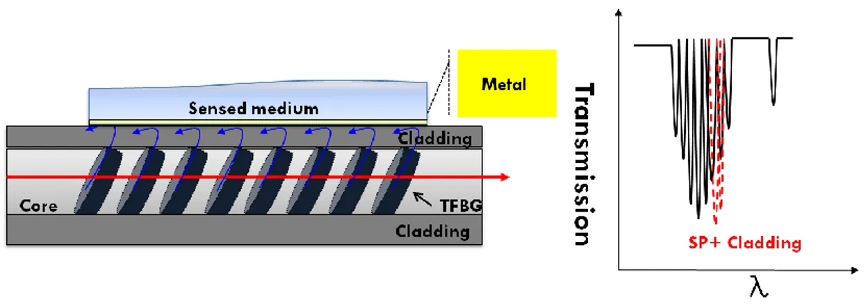
Tilting the FBG leads up to the tilted fiber Bragg grating (TFBG) which couple the forward Bragg core mode to the backward propagating cladding modes which can be observed as a series of resonance dips on the short wavelength side of the transmission spectrum as can be seen in Fig. 6 [22]. These modes can be excited efficiently with different tilt angles relative to the propagation axis of the fiber [22]. By simply increasing the tilt angle, stronger coupling occurs to cladding modes of relatively lower effective indices and vice versa [22]. FBGs and TFBGs theory will be discussed in more details in chapter 2.
Fig. 6. Tilted fiber Bragg grating (TFBG) and its transmission spectrum in optical fiber. On the other hand, LPG couples the core mode to a forward propagating cladding mode [22].
Fig. 7. Transmission spectrum using LPG in optical waveguide
Ctyroky et al. [23] proposed a theoretical model to use of the reflected or transmitted guided mode by a waveguide Bragg gratings (WBG) to detect the change in the sensed medium refractive index as can be seen in Fig. 8. [23]. This configuration gives sharp SPR compared to broad dip in the case of standard SPR sensors. The sensitivity of this SPR-WBG sensor is 50 nm/RIU and a resolution of 5
21 0 RIU can be reached by such a sensor [23].
Fig. 8. SPR-WBG sensor proposed by Ctyroky
Including the use of optical waveguides and optical fibers schemes, these schemes have used a surface Plasmon wave (SPW) as a sensing tool. This wave is not the pure surface Plasmon polariton (SPP) and it has a hybrid nature consisting of the guided core mode coupled to the SPP and thus it is weakly sensitive to changes in the effective refractive index of the SPP. Spackova
and Homola have proposed theoretically a multi-channel single-mode fiber optic SPR sensor based on coupling between the forward propagating core mode to the back-propagating mixed SPP-cladding modes by FBG [24]. Such a sensor gives a maximum Fig. of merit of 800 RIU1 , sensitivity of 200 nm/RIU and FWHM (Full Width Half Maximum) of 0.25 nm [8].
Pure SPP has almost all its field concentrated at the metal-dielectric interfaces and hence, it is highly sensitive to changes in the sensed medium refractive index [25]–[30]. Nemova and Kashyap [26] who were the first to have proposed exciting a pure SPP, suggested the use of a fiber Bragg grating to couple the guided mode to the SPP. The core and cladding radii are 13 m and 14 m respectively and the fiber has a coating of 10 - 20 nm gold layer [26]. In order to achieve a strong modal coupling between the core mode and the pure SPP by their configuration, they considered a specially designed optical fiber having very thin cladding which has a thickness of about 1 m. A theoretical model of an integrated planar SPP refractive index sensor exited by Bragg gratings has investigated in [28]. This model has a sensitivity of 250 nm/RIU and the bandwidth of the transmission spectrum is 500 pm. Nemova and Kashyap also suggested a configuration based on corrugated metal grating by writing the grating in the metal region itself [31]. It has been reported that even for a very thick cladding region of about 4.5µm, the grating length ranges typically between 4-6 cm with a sensitivity of 276 nm/RIU. Also, a pure SPP excitation by a corrugated metal LPG written in a metal coated planar integrated optical waveguide has been theoretically presented by Nemova and Kashyap [27]. Such a sensor exhibits of 1100 nm/RIU. A comparative study of metal coated side polished optical fiber Bragg gratings and LPG has been investigated theoretically [30]. The sensing characteristics of the FBG and the LPG have been analyzed and the structure of this sensor has been optimized with respect to maximum sensitivity. The proposed device gives a maximum sensitivity of 234 nm/RIU with FBG structure and 1288 nm/RIU with LPG structure. The sensing area of such a sensor is small and limited by the side-polished fiber block.
The cladding modes can be used for SPR sensing as has been demonstrated by Shevchenko and Albert [32]. Cladding modes are guided modes which can be excited easily by scattering light from the core of an optical fiber into the cladding [33]. FBG excited cladding modes are traditionally observed as a series of resonance peaks on the short wavelength side of the transmission spectrum of an FBG [22], [34], due to the limited overlap of the field of the
cladding modes with the guided mode field and the refractive index change across the core. These modes can also be excited with high efficiency as seen in the spectrum of a tilted fiber Bragg grating (TFBG) [22]. The cladding modes excited by the TFBG incident on the cladding metal interface transfer their power to the SPR at a resonant wavelength, by evanescent field coupling [15].
These are generally not observed in the reflection spectrum since they may be dissipated through propagation along the high-index polymer jacket of the fiber [33]. Recently, many schemes have been proposed to re-couple the reflected cladding modes back into the core. For example, a sensor has been proposed to re-couple cladding modes into the core of a short fiber excited by tilted fiber Bragg grating (TFBG) in which the sensor fiber was spliced to misaligned fiber [35], [36]. The sensor was used to measure the ambient refractive index, as a bend and vibration sensor [35], [36]. Such SRI sensor provides a dynamic range from 1.33 to 1.45 with sensitivity of 1100 nW/RIU at 1.33 RIU. The re-coupled cladding modes are within the wavelength band of 1538 nm and 1551 nm as merged band with no discrimination between individual cladding modes [36]. Another scheme to re-couple low order cladding modes excited by the TFBG in the core used an abrupt bi-conical fused taper [37].
Cladding modes have also been re-coupled into the core with a TFBG in which a short multimode fiber or a thin-core fiber section with a mismatched core diameter section was spliced between a single mode fiber and the TFBG [38]. The recoupled cladding modes in the best-case scenario are within the wavelength band of 1541 nm and 1549 nm. The sensor was used to measure the different refractive indices of glycerine-water solutions surrounding the TFBG providing a dynamic range from 1.33 to 1.45 RIU.
A scheme to couple the cladding modes into the core using a hybrid long period grating (LPG) and an FBG device has also been demonstrated. Here, the forward propagating core mode is partially coupled by the LPG into a cladding mode, which in turn is reflected with the core mode by a subsequent FBG, and partially re-coupled into the core by the same LPG [39], [40].
One of the problems in all these devices is that, generally when a large number of cladding modes are involved, it is difficult to capture all the modes within a large wavelength band. An efficient discrimination between individual cladding modes is another problem to consider. Recently, many surface Plasmon resonance (SPR) sensors have been proposed using the excitation of an SPR by tilted fiber Bragg gratings in gold-coated waveguides and fibers [41]. A
variety of schemes and devices have been proposed to exploit surface Plasmon resonance (SPR) on metal dielectric interfaces using TFBG. Shevchenko and Albert have experimentally observed the existence of SPR modifying the cladding modes by using fiber tilted Bragg gratings (TBG) at a small angle (2°–10°) as can be seen in Fig. 9 [32]. The sensitivity of such a sensor is 456 nm/RIU for RI operating range between 1.42 and 1.45 RIU. The spectral width of the SPR that is perturbing some of the cladding modes is 5nm [32].
Fig. 9. SPR-cladding modes coupling using tilted fiber Bragg gratings (TFBG).
Holmes had proposed the first demonstration of an experimental planar-integrated SPR-TBG sensor [42] which operates by coupling the core waveguide mode to a set of hybrid Plasmon-dielectric modes. The proposed device gives a maximum sensitivity of 566.9 nm/RIU by tracking the largest negative gradient of the cladding envelope where for some refractive index range, the Plasmon mode does affect and modify the form of the cladding mode envelope.
Different schemes have been proposed to track individual cladding mode resonances and their dependence on the state of polarization (SOP) to improve the resolution and the performance of the SPR-TFBG sensor [43]–[45]. The first Stokes parameter and the polarization dependent loss (PDL) have been used experimentally to interrogate the SPR-TFBG. Caucheteur proposed an experimental TFBG-SPR on a gold-coated SMF sensor using different properties such as the polarization dependent loss and the first Stokes parameter [46]. Such a sensor provides a sensitivity of 673 nm/RIU, again for a limited SRI range between 1.31 and 1.38 RIU with a FWHM of the SPR envelope of 5 nm.
Chen and Caucheteur experimentally demonstrated a TFBG-SPR scheme on a single mode fiber (SMF) coated with 2.6 μm low-index polymer of Cytop and 50 nm of gold [47]. The sensor
showed both, long range SPR (LRSPR) and short range SPR (SRSPR) coupled modes over the wavelength range from 1525 to 1610 nm. Their scheme achieved an experimental sensitivity of 115 nm/RIU attributed to the LRSPR coupling and 68 nm/RIU to the SRSPR when the SRI was 1.3335. The sensitivity varied based on the SRI to reach a maximum of 186 nm/RIU between 1.31 and 1.35 RIU [47]. Also, a TFBG-SMF has been coated with silver nanowires of 1-3 μm in length and 40-50 nm in diameter [48]. The PDL spectrum of the tilted fiber Bragg grating used to excite the cladding modes has been studied and shown to provide a sensitivity of 650 nm/RIU for a SRI range 1.330 to 1.347 RIU [48]. Chan and Albert demonstrated the transmission spectrum of TFBG reflected from a cleaved fiber end-facet coated with gold for sensing [49] where the measured spectrum represents the interference between the reflection spectrum and the transmion spectrum seen reflected from the fiber end.
One of the characteristics of all these devices using the TFBG-SPR sensors is that the cladding modes are not collected since they may be dissipated through propagation along the high-index polymer jacket of the fiber. Hence, the SPR is usually observed through the transmission spectrum alone. Also, the transmission spectrum has weak cladding resonances for the low-order cladding modes which limits the operating range of the device. Additionally, sensors operating in transmission require that the grating itself be coated in gold.
A multi-channel single-mode fiber (SMF) SPR sensor scheme using fiber Bragg gratings (FBG) has been proposed theoretically [24]. Here, the multichannel is achieved by a sequence of FBGs of different periods where the forward propagating core mode is partially coupled to backward travelling cladding modes. The sensor provided a calculated sensitivity of 200 nm/RIU between 1.32 and 1.325 RIU [24]. However, this approach requires very strong gratings to be inscribed and should be used with apodized FBGs for a clear SP resonance signature.
Albert et al. [50] have demonstrated a TFBG-SPR biochemical sensor in SMF coated with 30-50 nm of gold functionalized with aptamer receptor molecules. The sensor can act as a stand-alone device or as a multi-sensor platform. They proposed a multiplexing scheme based on multi-fiber sensing devices in which each individual fiber represented one channel of the multiplexed system [50]. The multi-fiber TFBG-SPR sensing devices in SMF coated with 30-50 nm of gold attached [50]. The device provides a sensitivity of 500 nm/RIU between 1.32 and 1.42 RIU. The concatenation of SPR sensors has not been demonstrated experimentally in the proposed schemes
using TFBGs in a single optical fiber. Such cascaded scheme allows the sensing of different analytes by positioning a number of in-line TFBGs in which the wavelength operating range of each channel can be engineered as required. Also, the effect of incorporating a layer of silicon on the metalized TFBG-SPR sensors has not been demonstrated yet by the proposed schemes where the silicon layer is expected to tune the SRI operating range and to enhance the sensitivity of the TFBG-SPR sensor. These issues have been presented for the first time and their impact in the field has been demonstrated experimentally through this dissertation in chapter 3 to 6.
1.3 Basics of Surface Plasmon Resonance
For SPRs to exist, the real part of the dielectric constant of the metal must be negative and its magnitude must be greater than that of the dielectric region [2]. The coupling of the light to the surface Plasmon wave (SPW) requires a coupling prism, waveguide or a periodic grating surface [2].
SPR sensors can be characterised by important parameters: sensitivity, detection accuracy known as signal to noise ratio (SNR), resolution, operating range, and Figure of merit. Sensitivity of SPR sensor can be characterized by the shift in the monitored parameter, wavelength of our proposed device, to the parameter to be determined, the refractive index of sensed medium of our proposed device,: S n (1-1)
Resolution of SPR sensor is the smallest change in the parameter to be determined which produces a detectable change in the sensor output. It has to be pointed out that the resolution of the sensor depends on the sensor properties and on the accuracy of the sensor monitoring devices such as the optical spectrum analyzer (OSA) [2], [10], [11]. Another important parameter to characterize SPR sensors related to resolution is the detection accuracy is the signal to noise ratio (SNR). The detection accuracy or the SNR can be characterized by how accurately the parameter to be monitored, wavelength or resonance angle, of the sensor can be detected. Hence the parameter to be determined represented by the refractive index of the sensing layer in our detection scheme [13] where apart from the limitations of a real instruments, the detection accuracy depends on the width of the SPR dip. Therefore, if ∆λFWHM is the full width half
maximum (FWHM) of the SPR dip corresponding to 0.5 reflectance, the SNR of the SPR sensor with wavelength interrogation can be defined as [13]:
F W H M S N R (1-2) It has to be pointed out that the narrower the SPR curve, the higher is the SNR. For better performance of the SPR sensor, sensitivity and SNR have to be as high as possible to give better sensing characteristic. SPR sensor’s sensitivity and SNR can be used to introduce other parameter called Figure of merit defined by:
F W H M S (1-3) SPR sensing devices showing a bigger are capable of giving higher resolution [14]. An operating range which can be measured by a SPR sensor is the range of values of the parameter to be determined which is the sensed medium’s refractive index for our proposed device [11]. In the subsequent paragraphs, we will describe the phase matching (PM) condition which has to be satisfied in order to excite the SPR coupling.
The incident wave vector (the propagation constant of the evanescent wave) is given by the following expression [2]:
𝛽𝑖 = (2𝜋𝜆) 𝑛 ∗ 𝑠𝑖𝑛𝜃𝑖 (1-4)
where θi is the incident light angle, λ is the wavelength of the incident light, (2π/λ) is the
free-space wave number and n is the refractive index of the fiber (silica).
If the metal film is sufficiently thin (less than 100 nm for light in visible and near infrared part of spectrum), the evanescent wave penetrates through the metal film and couples with a surface Plasmon at the outer boundary of the metal film [2]. The wave vector of the Plasmon mode, the propagation constant of the surface Plasmon propagating along a thin metal film, is described by the following expression [2]
𝛽𝑠𝑝 = (2𝜋𝜆) ∗ √εεm∗εd
Where εd and εm are the dielectric permittivity constants of the metal film and the dielectric exit
medium, respectively.
In order for the coupling between the evanescent wave and the surface Plasmon to occur, the propagation constant of the evanescent wave 𝛽𝑖 and that of the surface Plasmon 𝛽𝑠𝑝 have to be equal:
i R e
s p (1-6)Thus
(2𝜋𝜆) 𝑛 ∗ 𝑠𝑖𝑛𝜃𝑖 = 𝑅𝑒 {(2𝜋𝜆) ∗ √εεm∗εd
d+εm} (1-7)
The dielectric constant of metals at optical wavelengths is complex [51]:
εm = εm(Re)+ i ∗ εm(Im) (1-8) which is equal to the square of the complex refractive index [52] :
εm = εm(Re)+ i ∗ εm(im) = ἠ2 = (n + i ∗ k)2 = (n2− k2) + i ∗ 2nk (1-9) Where k is the extinction coefficient or the index of absorbtion or imaginary part of the complex refractive index. In most cases the Drude model is invoked to characterize the frequency dependence of the metallic dielectric function:
εm = 1 − wp
2
w(w+i γ) (1-10)
where ωp is the bulk plasma frequency, γ is the relaxation time [52]:
2 1 / 2 0 ( ) p e N e w m (1-11)
where N is the density of conduction electrons, me is their effective optical mass and e is the
charge of the electron.
It has to be noted that the complex refractive index of gold at 1550 nm is [53] equal to ἠ= 0.55 + 11.5 i. Also the permittivity of Au is equal to εAu = −131.95 − i 12.65 = ἠ2 [51]. In the subsequent paragraphs, we introduce a theoretical analysis and model of the SPR on three layers consisting of dielectric–metal–dielectric interface as can be seen in Fig. 10. The magnetic
field component of SPR on this interface for a gold metal film of different thicknesses where the SPR can exist in the form of transverse magnetic (TM) wave has been simulated. TM meaning that only electric fields Ex, Ez and the magnetic field Hy exist (x is normal to the surface, z and y
run along the surface with z being the direction of propagation ). The model represents the theoretical analysis of the SPR on three layers planar device consisting of dielectric–metal– dielectric interface. As the geometry of the SPR optical fiber sensor is more complicated, the single-mode optical fiber can be substituted by an equivalent single-mode planar waveguide with an identical propagation constant of the mode. The resulting planar SPR sensor structure can be analyzed using the mode expansion and propagation method [54], [55]. Also, the structure can be analyzed using a simple first-order perturbation method proposed by Kumar and Varshney [56]– [58] where the core of the fiber is considered as a perturbed scheme of an equivalent rectangular core region characterized by a separable index profile keeping the same area and aspect ratio. In order to obtain the respective propagation constants and field distributions, wave equations are then solved for the equivalent rectangular waveguide. Finally, a first order correction is used to obtain the propagation constants of the mode of the given fiber structure by considering the dielectric constant difference between the two structures [25], [29].
Fig. 10. Gold metal layer sandwiched between two infinite dielectric layers.
The electrical field and the magnetic field components where the modal fields are solutions to the following source-free Maxwell equations [2]:
∇ . 𝐷 = 0 (1-12)
∇ 𝑥 𝐸 = −𝜇0 𝜕 𝐻
𝜕𝑡 (1-14)
∇ 𝑥 𝐻 = 𝜀0𝑛2
𝜕 𝐸
𝜕𝑡 (1-15)
where 𝐸 is the electric field (v/m), 𝐵 is the magnetic field (tesla), 𝐷 is the electric displacement field (coulomb/m2), and 𝐻 is the magnetizing field (A/m).
𝜀0 = 8.85.∗ 10−12 𝐹/𝑚 , is the permittivity of free space and 𝜇
0 is the permeability of free space
(H/m).
∇. is the divergence operator (1/m) and ∇ 𝑥 is the curl operator (1/m) where the curl vector differential operator is defined as follows:
∇ 𝑥 𝐻 = (𝜕 𝐻𝑧 𝜕𝑦 − 𝜕 𝐻𝑦 𝜕𝑧 ) 𝑥0+ ( 𝜕 𝐻𝑥 𝜕𝑧 − 𝜕 𝐻𝑧 𝜕𝑥 ) 𝑦0+ ( 𝜕 𝐻𝑦 𝜕𝑥 − 𝜕 𝐻𝑥 𝜕𝑦 ) 𝑧0 (1-16) where H = (𝐻𝑥, 𝐻𝑦, 𝐻𝑧) are scalar and vector functions on Cartesian coordinates(x,y,x) and 𝑥0, 𝑦0 𝑎𝑛𝑑 𝑧0 are unit vectors. The modal fields can be expressed in the forms:
𝐸 = 𝑒(𝑥, 𝑦)𝑒𝑖(𝑤𝑡−𝛽𝑧)
(1-17) 𝐻 = ℎ(𝑥, 𝑦)𝑒𝑖(𝑤𝑡−𝛽𝑧)
(1-18) 𝛽 is the propagation constant, 𝑤 is the radial frequency of radiation connected with the wavelength 𝜆 = 2𝜋𝑐/𝑤.
By solving (1-15) with respect to x: 𝜕 𝐻𝑧 𝜕𝑦 − 𝜕 𝐻𝑦 𝜕𝑧 =𝜀0𝑛2 𝜕 𝐸𝑥 𝜕𝑡 (1-19) Thus 𝑖 𝛽 𝐻𝑦 = 𝜀0𝑛2 𝑖 𝑤 𝐸 𝑥 (1-20) Thus
𝐸𝑥 = 𝛽
𝜀0𝑛2 𝑤 𝐻𝑦 (1-21)
By solving (1-15) with respect to z: 𝜕 𝐻𝑦 𝜕𝑥 − 𝜕 𝐻𝑥 𝜕𝑦 = 𝜀0𝑛2 𝜕 𝐸𝑧 𝜕𝑡 (1-22) Thus 𝜕 𝐻𝑦 𝜕𝑥 = 𝜀0𝑛2 𝑖 𝑤 𝐸𝑧 (1-23) Thus 𝐸𝑧 = 1 𝑖 𝜀0𝑛2 𝑤 𝜕 𝐻𝑦 𝜕𝑥 (1-24)
Using equation (1-14) with respect to y, we have 𝜕 𝐸𝑥 𝜕𝑧 − 𝜕 𝐸𝑧 𝜕𝑥 = −𝜇0 𝜕 𝐻𝑦 𝜕𝑡 (1-25) on solving we get −𝑖𝛽 𝐸𝑥−𝜕 𝐸𝑧 𝜕𝑥 = −𝜇0 𝑖 𝑤 𝐻𝑦 (1-26)
and then we get
−𝑖𝛽2 1 𝜀0𝑛2 𝑤 𝐻𝑦 − 1 𝑖 𝜀0𝑛2 𝑤 𝜕2 𝐻 𝑦 𝜕𝑥2 = −𝜇0 𝑖 𝑤 𝐻𝑦 (1-27) Thus 𝜕2 𝐻 𝑦 𝜕𝑥2 = 𝐻𝑦 (−𝜀0𝑛2 𝑤2 𝜇0− 𝛽2 ) (1-28) 𝜕2 𝐻 𝑦 𝜕𝑥2 = 𝐻𝑦 (𝛽2− 𝑛2 𝑤2 𝑐2 ) (1-29) Thus 𝜕2 𝐻 𝑦 𝜕𝑥2 = 𝐻𝑦 (𝛽2− 𝑘2 𝜀 ) = 𝐻𝑦 𝛾2 (1-30)
𝛾12 = 𝛾
32 = 𝛽2− 𝜅2𝜀𝑑 (1-31)
𝛾22 = 𝛽2− 𝜅2𝜀
𝑚 (1-32)
For the dielectric and by solving (1-30)
𝐻𝑦(𝑥)= { 𝐴𝑒−𝛾1𝑥, 𝑥 > 𝑑
𝐶𝑒𝛾1𝑥 𝑥 < −𝑑 (1-33)
and for the metal:
𝐴𝑛𝑡𝑖𝑠𝑦𝑚𝑚𝑒𝑡𝑟𝑖𝑐 𝑆𝑃: 𝐻𝑦(𝑥) = 𝐵 sinh(𝛾2𝑥), |𝑥| < 𝑑
𝑆𝑦𝑚𝑚𝑒𝑡𝑟𝑖𝑐 𝑆𝑃: 𝐻𝑦(𝑥) = 𝐵 cosh(𝛾2𝑥), |𝑥| < 𝑑 (1-34) This gives none-zero electric and magnetic field components for the symmetric and anti-symmetric modes.
All field components of the SPR propagating in the planar structure along the z-axis contain a common factor 𝑒𝑖(𝑤𝑡−𝛽𝑧) where 𝛽 is the propagation constant, 𝑤 is the radial frequency of radiation connected with the wavelength 𝜆 = 2𝜋𝑐/𝑤.
Each layer of the structure can be characterised by the phase parameters: 𝛾12 = 𝛾
32 = 𝛽2− 𝜅2𝜀𝑑
𝛾22 = 𝛽2 − 𝜅2𝜀 𝑚
(1-35)
𝜅 is the vacuum wave number and 𝜀𝑚, 𝜀𝑑 are the relative permittivity of the gold film and dielectric, respectively. The relative permittivity of gold is given by 𝜀𝑚= −131.96 − 12.69𝑖 and the
relative permittivity of silica as dielectric is equal to 1.4442. So the magnetic field of the
symmetric mode in the structure can be presented as: 𝐻𝑦(𝑥) = { 𝐴𝑒
−𝛾1𝑥, 𝑥 > 𝑑
𝐵 cosh(𝛾2𝑥), |𝑥| < 𝑑 𝐶𝑒𝛾1𝑥 𝑥 < −𝑑
(1-36)
The boundary conditions of Maxwell’s equations require that the components of the electric and magnetic field intensity vectors parallel to the boundaries of the wave guiding layer are
continuous at the boundaries (x = d and x = – d). Applying the boundary conditions at our structure gives: 𝐻𝑦(𝑥) 𝑎𝑡 𝑥 = 𝑑: 𝐴𝑒−𝛾1𝑑 = 𝐵 cosh(𝛾 2𝑑) (1-37) 𝐸𝑧(𝑥) 𝑎𝑡 𝑥 = 𝑑: 𝛾2 𝐵 𝜀𝑚sinh(𝛾2𝑑) = −𝐴 𝜀𝑑 𝛾1𝑒−𝛾1𝑑 (1-38)
Dividing the last two equations gives the following eigenvalue equation which determines 𝛽 using equations (1-35): tanh(𝑥) = − 𝜀𝑚 𝜀𝑑 √1 − 𝑣2 𝑥2 𝑥 = 𝛾2𝑑 𝑎𝑛𝑑 𝑣 = 𝜅𝑑√𝜀𝑑 − 𝜀𝑚 (1-39)
The constant A, B and C can be calculated from the boundary condition of 𝐻𝑦(𝑥) at both 𝑥 = 𝑑
and 𝑥 = −𝑑 as follow: 𝐻𝑦(𝑥) 𝑎𝑡 𝑥 = 𝑑: 𝐴𝑒−𝛾1𝑑 = 𝐵 cosh(𝛾2𝑑) (1-40) 𝐻𝑦(𝑥) 𝑎𝑡 𝑥 = −𝑑: 𝐶𝑒−𝛾1𝑑 = 𝐵 cosh(−𝛾2𝑑) = 𝐵 cosh(𝛾2𝑑) (1-41) Thus 𝐴 = 𝐶 = 𝐵𝑒𝛾1𝑑cosh(𝛾 2𝑑) (1-42)
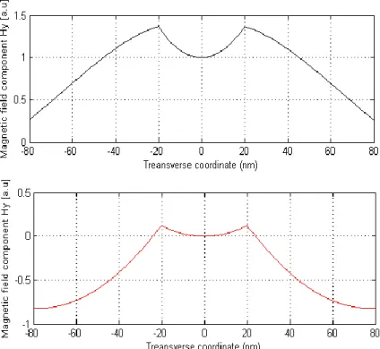
Fig. 11 shows the real and imaginary component of the magnetic field of symmetric mode SPR when the gold film thickness is equal to 40 nm.
Fig. 11. Simulation results of the real component of Hy (top) and imaginary (bottom) profiles of
SPR of symmetric mode of silica-gold-silica interface for a film thickness of 40 nm. Similarly, the magnetic field of the anti-symmetric mode in the structure can be presented as:
𝐻𝑦(𝑥) = { 𝐴𝑒
−𝛾1𝑥, 𝑥 > 𝑑
𝐵 sinh(𝛾2𝑥), |𝑥| < 𝑑 𝐶𝑒𝛾1𝑥 𝑥 < −𝑑
(1-43)
Applying the boundary conditions to the structure gives: 𝐻𝑦(𝑥) 𝑎𝑡 𝑥 = 𝑑: 𝐴𝑒−𝛾1𝑑 = 𝐵 sinh(𝛾 2𝑑) (1-44) 𝐸𝑧(𝑥) 𝑎𝑡 𝑥 = 𝑑: 𝛾2 𝐵 𝜀𝑚cosh(𝛾2𝑑) = −𝐴 𝜀𝑑 𝛾1𝑒 −𝛾1𝑑 (1-45)
Dividing the last two equations gives the following eigenvalue equation which determines 𝛽 using equations (1-35):
tanh(𝑥) = − 𝜀𝑑 𝜀𝑚 √ 1 1 − 𝑣𝑥22 𝑥 = 𝛾2𝑑 𝑎𝑛𝑑 𝑣 = 𝜅𝑑√𝜀𝑑− 𝜀𝑚 (1-46)
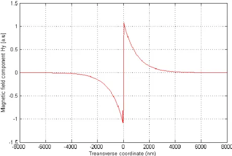
The constant A, B and C can be calculated from the boundary condition of 𝐻𝑦(𝑥) at both 𝑥 = 𝑑 and 𝑥 = −𝑑 as follow: 𝐻𝑦(𝑥) 𝑎𝑡 𝑥 = 𝑑: 𝑥 = 𝛾2𝑑 𝑎𝑛𝑑 𝑣 = 𝜅𝑑√𝜀𝑑− 𝜀𝑚 (1-47) 𝐴𝑒−𝛾1𝑑 = 𝐵 sinh(𝛾 2𝑑) (1-48) 𝐻𝑦(𝑥) 𝑎𝑡 𝑥 = −𝑑: 𝐶𝑒−𝛾1𝑑 = 𝐵 cosh(𝛾 2𝑑) (1-49) Thus 𝐴 = 𝐶 = 𝐵𝑒𝛾1𝑑cosh(𝛾2𝑑) (1-50) Fig. 12. shows the magnetic field component of SPR anti-symmetric mode when the gold film thickness is equal to 40 nm.
Fig. 12. Simulation of the Hy component profile of SPR anti-symmetric mode of
dielectric-gold-dielectric interface for a film thickness of 40 nm.
In addition to satisfying the phase-matching condition, coupling to the SPR needs the polarization state of the cladding modes to be matched to the SPR, since only the p-polarisation state (TM mode) is allowed; SPR only couples to one polarisation only. In the following paragraph, we show that only the TM mode can excite the SPR. We use a planar structure consisting of a metal-dielectric interface as an example to simplify the proof. As was mentioned earlier, the dielectric constant distribution is,
fo r > 0 (d ie le c tric ) fo r < 0 (m e ta l) d m x x x (1-51)Typically mis a complex quantity with its real part being negative and much larger than the
imaginary part. Firstly, we obtain the solutions of the wave equation of the TM mode and see under what conditions the interface supports a surface wave. The wave equation to be solved for the TM mode is:
2 2 2 2 0 2 0 y y H k n H x (1-52) i.e.
2 2 2 0 2 0 fo r x > 0 y d y d H k H d x (1-53) and
2 2 2 0 2 0 fo r x < 0 y m y d H k H d x (1-54)We take the solutions of the form,
2 2 2 0 2 2 2 0 ; f o r > 0 , = ; f o r < 0 , = d m x d d y x m m A e x k H B e x k (1-55)
Now, applying the boundary condition, i.e. continuity of y a n d 12 y d H H n d x at x = 0, we get, A = B, (1-56) and, d m d m A B (1-57) and thus we get,
2 2 2 2 2 0 2 2 2 2 2 0 d m d d d m m m k k (1-58)
this after simplification gives,
0 d m e ff m d n k (1-59)
The above TM solution is known as effective refractive index of the surface Plasmon wave (SPW). Secondly, we try to obtain the solutions of the wave equation of the TE mode and see under what conditions the interface may support a surface wave. For the TE mode, the wave equation which has to be solved is:
2 2 2 2 0 2 0 y y E k n E x (1-60)taking the solution of the form:
2 2 2 0 2 2 2 0 ; f o r > 0 , = ; f o r < 0 , = d m x d d y x m m A e x k E B e x k (1-61)
and applying the continuity of Eyand y d E d x at x = 0 we get, A = B (1-62) and dA mB (1-63) this implies that,
d m (1-64) The above condition cannot be satisfied as both themand d are positive quantities. This means
that a dielectric-metal interface cannot support a TE mode which is actually proofs that SPR only couples to one polarisation only which is the TM mode. However in the case of SPR excitation on a metal coated optical fiber, the cladding is a circular waveguide and it supports more complicated mode structures known as hybrid modes and we cannot consider the TE or TM modes only.
The proposed schemes in this dissertation are TFBG-SPR optical fiber sensors where the TFBG are coated with metals and coupling of the cladding modes to the SPR occurs if the phase matching condition (PM) is satisfied, as was mentioned previously in chapter 1. The excited cladding modes couple to the SPR are dissipated in the metal. This happens when the effective refractive index of cladding modes is close to that of the SPR, as determined by the SRI. The PM condition between a cladding mode and the SPR can be expressed as
d m d m c l c l n ) Re sin( (1-65)
where εm being the dielectric constant of the metal , εd is the dielectric constant of the sensing
medium around the metal, ncl is the cladding refractive index, and θcl is the angle of the cladding
mode ray incident on the cladding-metal interface.
Each cladding mode represents an optical ray striking the cladding-metal boundary at some angle of incidence according to the geometrical optics picture. The reflectance with respect to the incidence angle can be calculated in the Kretschmann configuration using the matrix method for a number of layers including the cladding, the coating, and the SRI [59], [60]. The reflection coefficient of the model for p-polarized light is R=|rp|2, where rp is the amplitude reflection
coefficient given by: ) ( ) ( ) ( ) ( 12 11 1 12 11 22 21 1 12 11 N N N N p q M M q q M M q M M q q M M r (1-66) where: d d d d d d d iq q i M cos sin / sin cos (1-67) 2 2 1/2 sin n qd d (1-68) 2 2 1/2 sin / 2 t n d d d (1-69) considering M as the characteristic matrix of the proposed structure consisting of N number of layers and where εd being the dielectric constant of the layer, n itsrefractive index, and td is the
thickness. The resonant angle corresponds to the localised minimum in the reflection coefficient [59]. Thus the SPR resonance angle as a function of the SRI can be simulated. The results of this simulation have been introduced in chapters 4 and 6 for TFBG-SPR sensors coated with chromium and gold with/without silicon. The above approach is developed for a planar geometry where it is possible to use this approach to predict the SPR and the cladding modes coupling, but still there is a need to develop a complete model taking into account the circular geometry of the optical fiber into account and to study how the results supported by the geometry of optical fiber differs from the results supported by the planar geometry.
![Fig. 4. Silicon-coated metalized Multi-mode optical fiber without using Bragg gratings [21]](https://thumb-eu.123doks.com/thumbv2/123doknet/2323611.29708/24.918.153.763.833.1005/silicon-coated-metalized-multi-optical-fiber-bragg-gratings.webp)