Single Conjugate Adaptive Optics for METIS
Thomas Bertram
a, Olivier Absil
b, Peter Bizenberger
a, Wolfgang Brandner
a, Florian Briegel
a,
Faustine Cantalloube
a, María Concepción Cárdenas Vázquez
a, Markus Feldt
a, Adrian M.
Glauser
c, Thomas Henning
a, Stefan Hippler
a, Armin Huber
a, Martin Kulas
a, Werner Laun
a,
Lars Mohr
a, Philip Neureuther
d, Andreas Obereder
e, Ralf-Rainer Rohloff
a, Silvia Scheithauer
a,
Horst Steuer
a, and Roy van Boekel
aa
Max-Planck-Institut für Astronomie, Königstuhl 17, 69117 Heidelberg, Germany
bSTAR Institute, Université de Liège, 19c allée du Six Août, bât B5c, 4000 Liège, Belgium
cInstitute for Particle Physics and Astrophysics, ETH Zürich, Wolfgang-Pauli-Str. 27, 8093
Zürich, Switzerland
d
Institute for System Dynamics, University of Stuttgart, Waldburgstraße 17/19, 70563
Stuttgart, Germany
e
MathConsult GmbH, Altembergerstraße 69, 4040 Linz, Austria
ABSTRACT
METIS, the Mid-infrared Imager and Spectrograph for the Extremely Large Telescope (ELT), is currently under development and has conducted the Preliminary Design Review in spring of 2019. An integral part of METIS is its Single Conjugate Adaptive Optics (SCAO) system, which will provide the required wavefront correction in conjunction with the adaptive mirrors in the telescope domain. It is optimized for the unique observing capabilities of METIS - especially for high contrast imaging in the mid-infrared. The coronagraphic observing modes impose a number of challenging requirements for adaptive and active beam correction. METIS SCAO is tasked to support all observing modes with AO wavefront correction, but also with differential tip/tilt-, NCPA-, and pupil position control. The SCAO Module is located inside the cryogenic environment of METIS and hosts a pyramid type wavefront sensor, operating in the near-infrared. The wavefront control loop, as well as a number of secondary control tasks, will be realized within the SCAO Control System. This paper outlines on the PDR design of METIS SCAO.
Keywords: SCAO, METIS, ELT, NIR wavefront sensor, pyramid wavefront sensor
1. INTRODUCTION
METIS will be installed on the Nasmyth platform A of the ELT. It covers the thermal/mid-infrared wavelength domain (2.9 µm – 13.5 µm) and provides the following observing modes:
• Imaging at L/M band (2.9 µm – 5.3 µm) and low/medium resolution (R∼1400) slit spectroscopy, as well as coronography for high contrast imaging (HCI).
• Imaging at N band (7.5 µm – 13.5 µm) and low/medium resolution (R∼350) slit spectroscopy, as well as coronography at N-band for HCI.
• High resolution (R ∼105) Integral Field Unit (IFU) spectroscopy at L/M band, including a mode with extended instantaneous wavelength coverage.
Focusing mostly on known, compact targets, METIS requires only a moderate imaging field of view (FoV) size: 10.005×10.005 in the L/M band and N band imager, and ∼ 0.0058×1.0000 in the IFU.
All METIS science cases require adaptive optics correction at or close to the diffraction limit. The atmospheric turbulence and additional dynamic wavefront distortions will be corrected by a SCAO subsystem. Its design is driven by the exo-planet science case.
METIS SCAO1operates in the near-infrared (NIR) wavelength regime and uses the light of a single Natural
Guide Star (NGS) located within a field of ∅ 2700 around the center of the science FoV. A number of distributed entities are involved: in the instrument domain, the AO system consists of the SCAO Module and the SCAO
Control System (SCAO CS). Further entities that are essential for SCAO are located in the telescope domain.
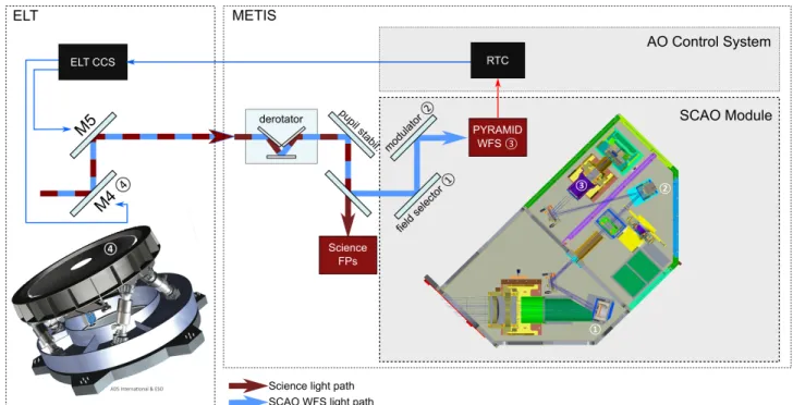
Figure1shows a simplified block diagram for METIS SCAO.
Figure 1. Control scheme for METIS SCAO. The components inside the grey boxes are part of METIS SCAO, those devices inside the dotted box labeled with ’ELT’ are part of the ELT infrastructure. Light propagates through telescope and instrument. The Near Infrared part of the light (blue) is directed to the SCAO Module, which uses a pair of field steering actuators ( 1 and , see Section2 3) and a pyramid WFS 3 to detect wavefront aberrations. The wavefront is reconstructed and correction signals are calculated by the instrument RTC, which sends the correction signals via the CCS of the ELT to the actuators of the wavefront control loop: the deformable mirror M4 4 and the field stabilization mirror M5.
The SCAO Module is located inside the cryostat of METIS. A cold dichroic AO pick-off mirror immediately in front of the SCAO Module is used to separate the NIR part of the light, which is used for wavefront sensing. The SCAO Module provides a Pyramid Wavefront Sensor (PYR WFS) as well as opto-mechanical actuators for field selection and modulation of the NGS in the field of view.
The SCAO Control System (SCAO CS) hosts the main wavefront control loop as well as a number of secondary control loops. A key entity of the SCAO CS is the Real-Time Computer (RTC). Its Hard Real-Time Core (HRTC) is used for the time critical aspects of the wavefront control loop: wavefront sensor signal processing, wavefront reconstruction and the determination of correction commands that are applied with the ELT quaternary mirror (M4) and ELT tip-tilt field stabilisation mirror (M5) via the Central Control System (CCS). Less time critical control tasks are realized outside of the RTC. These include the control of differential tip-tilt and the position of the pupil. HCI observing modes will require closed loop Non-Common Path Aberration (NCPA) compensation.
NCPA corrections will be determined by analyzing the science detector and Wavefront Sensor (WFS) data streams. Corrections will be applied via WFS signal offset commands.
2. SCAO AND HIGH CONTRAST IMAGING
As HCI is the driving science case for METIS, special attention has been payed to analyse the performance of the SCAO system with respect to contrast.
Two different approaches were used to analyze the performance of METIS SCAO: Numerical end-to-end (E2E) simulations2and synthetic modeling.3 In the latter the stationary output of the system, the AO corrected
phase spatial Power Spectral Density (PSD), is directly modeled based on a priori knowledge of the system’s behavior. It is well suited to assess main error contributions in the Adaptive Optics (AO) error budget. Error sources can be disentangled and studied individually, which is difficult to do in E2E simulations. The synthetic modeling with the PAOLA code base4,5 was done for the PDR baseline configuration of METIS SCAO, which
includes a loop rate of 1kHz, pupil sampling of 74×74 subapertures, and a delay of two frames.
λ⋅Fc: 763mas FITTING TOTAL SERVO-LAG ERROR ALIASING PHOTON NOISE 5 λ/D @ 3.7 µm 2 λ/D @ 3.7 µm
0
200
400
600
800
1000
Separation [mas]
10
-910
-810
-710
-610
-510
-410
-3Contrast
Figure 2. Synthetic modeling: the impact of residual phase error sources on the raw contrast. Fc is the cutoff frequency, the highest spatial frequency for which a correction can be applied. )
Figure2shows the contributions of the main AO residual phase errors to the raw contrast, which is directly derived from the PSD models. Note that the raw contrast is shown here and not the post-processed contrast,
which is the important performance metric for HCI. The servo-lag error, although small in the integrated phase variance, dominates especially at the low spatial frequency range which is most relevant for the inner working angle in HCI. The dominance of the servo-lag error is apparent up to a separation of 15 λ/D which is about 300 mas at L-band.
As temporal errors like servo-lag are the main culprits for the loss of raw contrast in the innermost region, special attention needs to be paid to the controller design and especially to the tip-tilt management. A simple integrator controller may allow to reach the residual pointing jitter requirements, but is most likely not providing optimum results. More detailed analyses are being performed and alternative solutions studied.6
3. THE SCAO MODULE WITHIN METIS
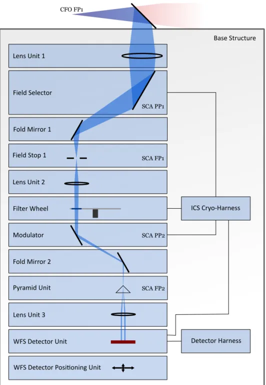
The SCAO Module is located in the lower region inside the cryostat (cf. Figure 3, left panel). It subsumes the physical components that are required in the instrument domain to provide SCAO wavefront correction for METIS: the PYR WFS and all associated optical components, as well as auxiliary actuators to bootstrap, maintain and optimize the optical configuration for wavefront sensing. The right panel in Figure 3 shows the opto-mechanical design, Figure4 shows a functional block diagram of the SCAO module.
Figure 3. Left: SCAO Module location inside the METIS cryostat. Right: Opto-mechanical design of the SCAO module. The Field Selector is a unit at the entrance of the SCAO Module. Its task is to choose the field to be directed towards the WFS, which allows to select the natural guide star from anywhere in the scientific field of view. It is realized as an actively controlled tip/tilt mirror located in the first pupil plane of the SCAO Module. A challenge for the actuator is the combination of high angular resolution over a large travel range at cryogenic operating conditions. The setting requires about 1.6·105resolution elements over a travel range of 6°.
A second tip/tilt mirror in the optical train is the Modulator. It is used to modulate the light over the four facets of the pyramid, thus allowing to trade linear range and sensitivity of the pyramid WFS. A sinusoidal tip-tilt motion of the mirror will cause the image of the natural guide star to move along a circular path around the tip of the pyramid. The frequency with which the circular path is commanded has to be synchronized with the readout frequency of the detector (up to 1 kHz) and the radius of the circular path needs to be adjustable up to 10 λ/D. Again, the realization of such an actuator for cryogenic operating conditions is a challenge. First feasibility studies had been carried out with positive outcome for both cryogenic tip/tilt actuators. In the meantime the prototyping of both actuators has started.
A filter wheel allows to select bandpass and neutral density filters to avoid saturation on the brightest targets. Field stops are introduced in the focal plane downstream of the Field Selector and at the pyramid itself. The WFS signal will be obtained with a SAPHIRA detector.7
Base Structure Field Stop 1 Lens Unit 2 Filter Wheel Modulator Fold Mirror 2 Pyramid Unit Lens Unit 3 WFS Detector Unit
WFS Detector Posi�oning Unit Lens Unit 1 Fold Mirror 1 Field Selector ICS Cryo-Harness Detector Harness CFO FP1 SCA FP1 SCA PP1 SCA PP2 SCA FP2
Figure 4. Functional block diagram for the SCAO Module.
4. THE SCAO CONTROL SYSTEM
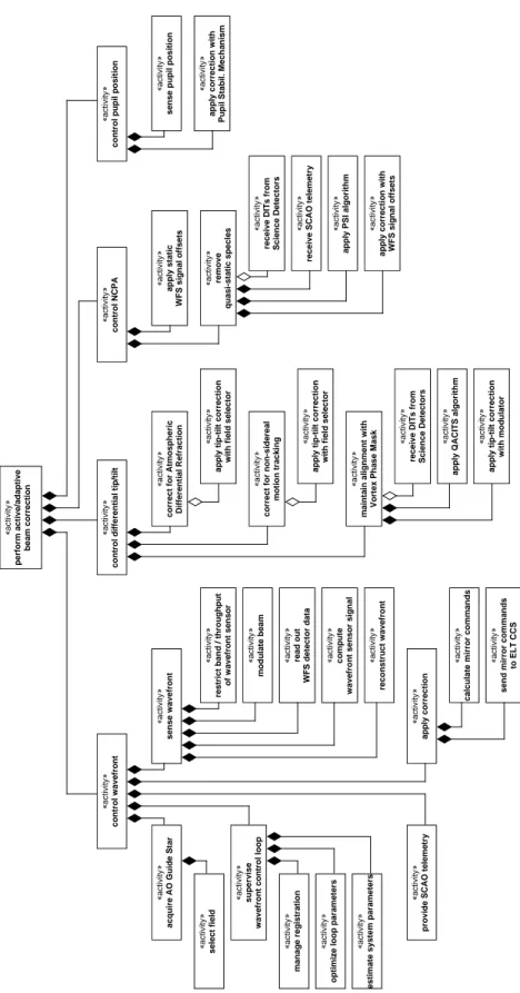
Wavefront correction is the most prominent but not the only activity the SCAO CS is tasked with. The main activities are shown in the activity tree in Figure5. The four main active/adaptive beam correction activities of METIS SCAO are:
«activity»
receive SCAO telemetry
«activity»
receive DITs from Science Detectors
«activity»
receive DITs from Science Detectors
«activity»
apply static
WFS signal offsets
«activity»
apply correction with WFS signal offsets
«activity» remove
quasi-static specles
«activity»
send mirror commands
to ELT CCS
«activity»
apply tip-tilt correction
with field selector
«activity»
correct for non-sidereal
motion tracking
«activity»
correct for Atmospheric Differential Refraction
«activity»
apply tip-tilt correction
with modulator
«activity» compute
wavefront sensor signal
«activity»
estimate system parameters
«activity» select field
«activity»
restrict band / throughput
of wavefront sensor
«activity»
apply correction with
Pupil Stabil. Mechanism
«activity»
sense pupil position
«activity»
optimize loop parameters
«activity»
calculate mirror commands
«activity»
reconstruct wavefront
«activity» read out
WFS detector data
«activity»
modulate beam
«activity»
apply tip-tilt correction
with field selector
«activity»
provide SCAO telemetry
«activity» apply correction «activity» sense wavefront «activity» manage registration «activity» supervise
wavefront control loop
«activity»
acquire AO Guide Star
«activity»
apply QACITS algorithm
«activity»
maintain alignment with
Vortex Phase Mask
«activity»
apply PSI algorithm
«activity»
control NCPA
«activity»
control differential tip/tilt
«activity»
control pupil position
«activity»
perform active/adaptive
beam correction
«activity»
control wavefront
tasks such as maintaining the registration between WFS and deformable mirror.
Control differential tip-tilt: this function ensures the correct pointing direction in the science path by
com-pensating slow differential tip/tilt effects between the WFS and the science path in open or closed loop. It includes the correction for atmospheric differential refraction between science and wavefront sensing bands, but also non-sidereal motion observations with SCAO operating on a nearby NGS. In the case of HCI observations differential tip/tilt will be corrected in closed loop.
Control non-common path aberrations: NCPA between the WFS and the science focal planes are not
prop-erly detected by the wavefront control loop itself and degrade the performance in the science path. HCI observations are especially sensitive to slowly varying NCPA. These observing modes will be supported by closed loop NCPA control.
Control pupil position: the exit pupil of the telescope-instrument system has to be controlled to maintain a
fixed position. The lateral pupil position is, otherwise, affected by flexure of the telescope and the imperfect alignment of the derotator. The WFS detector telemetry is used as input to control the position of the pupil downstream of a Pupil Stabilization Mirror in the common path.
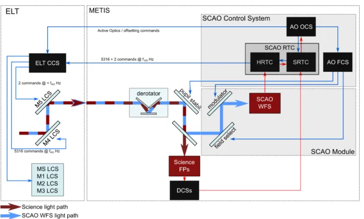
Figure6 shows a simplified block diagram with the main SCAO CS components and the data flow between. The SCAO RTC consists of two parts: a Soft Real-Time Cluster (SRTC) and a Hard Real-Time Core (HRTC). Especially the HRTC has challenging requirements in terms of computing power, hard real-time constraints, and network throughput. Different hardware platforms are being investigated to identify the most suitable solution for the METIS RTC.8
Figure 6. Signal flow for METIS SCAO. Red arrows indicate measurement signal flow, blue arrows command flow. Red boxes represent sensors, black boxes represent control services. The Hard Real-Time Core (HRTC) within the Real-Time Computer (RTC) is responsible for the core wavefront control loop, data products that rely on SCAO telemetry are computed in the Soft Real-Time Cluster (SRTC). Secondary control tasks, such as registration management, modulation and field selection will be performed outside of the SCAO RTC.
REFERENCES
[1] Bertram, T., Absil, O., Bizenberger, P., Brand ner, W., Briegel, F., Cantalloube, F., Carlomagno, B., Cárde-nas Vázquez, M. C., Feldt, M., Glauser, A. M., Henning, T., Hippler, S., Huber, A., Hurtado, N., Kenworthy, M. A., Kulas, M., Mohr, L., Naranjo, V., Neureuther, P., Obereder, A., Rohloff, R.-R., Scheithauer, S., Shatokhina, I., Stuik, R., and van Boekel, R., “Single conjugate adaptive optics for METIS,” in [Proc.SPIE],
Society of Photo-Optical Instrumentation Engineers (SPIE) Conference Series 10703, 1070314 (Jul 2018).
[2] Hippler, S., Feldt, M., Bertram, T., Brandner, W., Cantalloube, F., Carlomagno, B., Absil, O., Obereder, A., Shatokhina, I., and Stuik, R., “Single conjugate adaptive optics for the ELT instrument METIS,”
Exper-imental Astronomy 47, 65–105 (Apr 2019).
[3] Rigaut, F. J., Veran, J.-P., and Lai, O., “Analytical model for shack-hartmann-based adaptive optics sys-tems,” Proc.SPIE 3353, 3353 – 3353 – 11 (1998).
[4] Jolissaint, L., Véran, J.-P., and Conan, R., “Analytical modeling of adaptive optics: foundations of the phase spatial power spectrum approach,” Journal of the Optical Society of America A 23, 382–394 (Feb. 2006). [5] Jolissaint, L., “Synthetic modeling of astronomical closed loop adaptive optics,” Journal of the European
Optical Society 5, 10055 (Nov. 2010).
[6] Neureuther, P. L., Bertram, T., and Sawodny, O., “A new SCAO control concept based on mechanical mirror modes for METIS,” in [Adaptive Optics for Extremely Large Telescopes 6 – Conference Proceedings], (2019). [7] Finger, G., Baker, I., Alvarez, D., Ives, D., Mehrgan, L., Meyer, M., Stegmeier, J., and Weller, H. J.,
[8] Kulas, M., Steuer, H., Bertram, T., and Briegel, F., “METIS AO RTC Prototype,” in [Adaptive Optics for