HAL Id: hal-01700298
https://hal.archives-ouvertes.fr/hal-01700298v2
Submitted on 25 Sep 2018
HAL is a multi-disciplinary open access
archive for the deposit and dissemination of
sci-entific research documents, whether they are
pub-lished or not. The documents may come from
teaching and research institutions in France or
abroad, or from public or private research centers.
L’archive ouverte pluridisciplinaire HAL, est
destinée au dépôt et à la diffusion de documents
scientifiques de niveau recherche, publiés ou non,
émanant des établissements d’enseignement et de
recherche français ou étrangers, des laboratoires
publics ou privés.
A Probabilistic Parallel Bit-Flipping Decoder for
Low-Density Parity-Check Codes
Khoa Le, Fakhreddine Ghaffari, Lounis Kessal, David Declercq, Emmanuel
Boutillon, Chris Winstead, Bane Vasic
To cite this version:
Khoa Le, Fakhreddine Ghaffari, Lounis Kessal, David Declercq, Emmanuel Boutillon, et al.. A
Prob-abilistic Parallel Bit-Flipping Decoder for Low-Density Parity-Check Codes. IEEE Transactions on
Circuits and Systems I: Regular Papers, IEEE, 2018, pp.1 - 14. �10.1109/TCSI.2018.2849679�.
�hal-01700298v2�
A Probabilistic Parallel Bit-Flipping Decoder for
Low-Density Parity-Check Codes
Khoa Le, Fakhreddine Ghaffari, Member, IEEE, Lounis Kessal, Member, IEEE,
David Declercq, Senior Member, IEEE, Emmanuel Boutillon, Senior Member, IEEE,
Chris Winstead, Senior Member, IEEE and Bane Vasi´c, Fellow, IEEE
Abstract—This paper presents a new Bit Flipping (BF) decoder, called the Probabilistic Parallel Bit Flipping (PPBF) for Low-Density Parity-Check (LDPC) codes on the Binary Symmetric Channel. In the PPBF, the flipping operation is performed in a probabilistic manner which is shown to improve significantly the error correction performance. The advantage of the PPBF also comes from the fact that no global computation is required during the decoding process and that all the computations can be executed in the local computing units and in-parallel. The PPBF provides a considerable improvement of the operating frequency and complexity, compared to other known BF decoders, while obtaining a significant gain in error correction. An improved version of the PPBF, called non-syndrome PPBF (NS-PPBF) is also introduced, in which the global syndrome check is moved out of the critical path and a new terminating mechanism is proposed. In order to show the superiority of the new decoders in terms of hardware efficiency and decoding throughput, the corresponding hardware architectures are presented in the second part of the paper. The ASIC synthesis results confirm that the operating frequency of the proposed decoders is significantly improved, compared to that of the BF decoders in the literature while requiring lower complexity to be efficiently implemented.
Keywords—Low-Density Parity-Check codes, iterative decoding, probabilistic Bit Flipping decoding, high decoding throughput, low-complexity implementation.
I. INTRODUCTION
Low-Density Parity-Check (LDPC) codes were introduced
by Gallager in 1963 and they have been adopted as a part
of several standards, such as IEEE 802.11n, 802.16a, etc. due to their outstanding error correction capability [1], [2]. LDPC codes can be decoded by two classes of decoding algorithms:
soft-information message passing algorithms, e.g., Min-Sum
This work was funded by the french ANR under grant number ANR-15-CE25-0006-01 (NAND project) and by NSF under grant ECCS-1500170.
Khoa Le Trung, Fakhreddine Ghaffari, David Declercq and Lou-nis Kessal are with ETIS, UMR8051/ Universit´e Paris Sein/ Universit´e de Cergy-Pontoise/ ENSEA/ CNRS, 95014 Cergy-Pontoise, France (email: {khoa.letrung,fakhreddine.ghaffari,declercq,kessal}@ensea.fr).
Emmanuel Boutillon is with the lab-STICC, UMR 6285, Universit´e de Bretagne Sud, 56321 Lorient, France, (email: [email protected]).
Chris Winstead is with the Department of Electrical and Com-puter Engineering, Utah State University, UT 84322-4120 USA, (email: [email protected]).
Bane Vasi´c is with Department of Electrical and Computer Engi-neering, University of Arizona, Tucson, AZ, 85719 USA, (email: [email protected]).
A part of this work was presented at the International Conference on Advanced Technologies for Communication, Quynhon, Vietnam, Oct. 2017.
(MS), Sum Product (SP) [3], or hard-decision algorithms such as Bit Flipping (BF) and Gallager-A,B [4] [5]. The soft-information decoding algorithms provide a very good decoding performance but require a large computation resources. They exhibit, therefore, very high complexity in hardware realization [3]. On the contrary, the hardware implementations of hard-decision decoders were shown to have low complexity thanks to the simple computation units and smaller connection net-works, but they are weak in error correction. The increasing demand of massive data rates in several applications, such as optical communications, high-speed Ethernet [6], data storage devices [7] [8] [9] or the New Radio of 5G enhanced mobile broadband (eMBB) [10], will require higher decoding through-put. In such applications, hard decision decoders become the promising candidates thanks to their simple computations and hence, low complexity and high decoding throughput, provided that the decoding performance is improved. In this paper, we focus on the Bit Flipping (BF) hard decision decoder to not only enhancing the decoding throughput and reducing the decoder complexity but also improving the error correction performance. Furthermore, we focus on the decoders which require only the hard information from the channel. These decoders could be used when the channel soft-information is unable to obtain or requires a long latency to be generated, such as the storage system [11] [12].
The BF decoding concept is firstly introduced by Gallager [4]. It involves passing binary messages iteratively between two groups of nodes: the Variable Nodes (VNs) and the Check Nodes (CNs), and it uses the channel hard-information as the input values. The CN uses the exclusive-OR (XOR) operations. In each iteration, a VN is flipped if the number of unsatisfied neighboring CNs is higher than a predefined threshold. The BF has a very low complexity decoder but provides a weak error correction, compared to the soft-decision decoders. Several BF decoders have been latter proposed in literature, in which the Gradient Descent Bit Flipping (GDBF) and the Probabilistic Gradient Descent Bit Flipping (PGDBF), introduced by Rasheed et al. in [13], could be seen as the most promising algorithms, in terms of error correction. In the GDBF, the CN operation is the XOR calculation as in the standard BF decoder, while VN computes a function called
inversion or energy function derived from a gradient descent
formulation. A VN is flipped when its energy value is a maximum, compared to all other energies. The GDBF provides a very good error correction and it is better than the previously introduced deterministic BF decoders. The PGDBF is a variant
0.01 10−8 10−7 10−6 10−5 10−4 10−3 10−2 10−1
Channel Crossover Probability, α
F rame Error Rate (FER) BF GDBF PGDBF Proposed 2 Proposed 1 MS
Fig. 1: The evolution in term of decoding performance of BF decoders on the Tanner code [15].
of the GDBF, introduced also in [13]. The PGDBF follows precisely the decoding steps of the GDBF, and differs only in the VN flipping operations. Unlike the GDBF in which the VNs that satisfy flipping condition are automatically flipped, all the flipping candidates in PGDBF are only flipped with a probability of p (0 < p < 1). Interestingly, this probabilistic behavior improves the decoding performance, far better than the original GDBF and very close to MS [14]. The evolution of BF performance improvement is shown in Fig. 1 on the well-known Tanner code [15]. Another newly proposed BF decoder is introduced by J. Jung [11], and is called Multi-Bit Flipping (MBF). The MBF scenario is in line with our target in which the decoder requires only hard information from the channel for decoding. The VNs of MBF also compute at each iteration the energy value basing on its neighbor CN values. The novelty comes from the fact that, at each iteration of MBF, only a constant number of VNs are allowed to flip to avoid the
overcorrection. For example, only 4 VNs are flipped at each
iteration. This truly helps the MBF avoid VN miss-flipping and offers a considerable improvement in error correction.
The GDBF and PGDBF implementations can be found in [14] and MBF is implemented in [11]. A drawback of these BF decoders is that a global operation (the Maximum Finder -MF in [14] and N-to-4 sorter in [11]) is required to identify the maximum among the VN energy values. This global function operates on the large number of energy values, and in the hardware implementations it lengthens the decoder data path and limits the maximum achievable frequency, especially when the codeword length is long. Although the reported decoding throughput of the above decoders is very promising, the global operation are the main obstacle for further improving the operating frequency and therefore, limit the increasing of the decoding throughput.
Another global computing block, which also limits the maximization of the operating frequency, is the Syndrome Check (SC) module. During the decoding process, the SC module verifies all the CN values and indicates at its output
the stopping signal when all of them are satisfied, i.e., when
all of CN values are 0’s. We show in this paper that, the SC
is an important module for prior-introduced BF decoders to obtain the decoding success but it can not be fully parallelized to improve the decoding speed. The hardware implementation of the SC module has all of the CN outputs as its inputs and the data path becomes significantly long when the number of CNs is large. A BF decoder in which the SC is eliminated from the data path, would provide a significant improvement in operating frequency.
This paper presents a new probabilistic parallel BF decoder (PPBF) in which no global operation is required. The flipping decision in each VN of PPBF is made locally in the VN basing only on its channel value, neighbor CN values and a probabilistic binary signal. In the PPBF, depending on the computed energy value, the VN will be flipped with the corresponding probability. Therefore, at each iteration, all VNs in PPBF could be flipped (with different probabilities) and it is different from the PGDBF decoder where only the VNs having the maximum energy are the flip candidates. The data path is significantly shortened which results an enhancement of decoding throughput. More interestingly, by eliminating the global operation, PPBF becomes a low-complexity algorithm, comparable to the deterministic GDBF decoder, while having a better decoding performance than PGDBF and being very close to the MS performance. An improved version of PPBF, called Non-Syndrome Probabilistic Parallel Bit Flipping (NS-PPBF), is then introduced, further shortening the critical path by moving the global SC module out of the data path. In the NS-PPBF, when converging to a correct codeword, the decoder will stop flipping thanks to a specific flipping mechanism. NS-PPBF additionally improves the decoding frequency, compared to PPBF while maintaining the good error correction capability. The rest of the paper is organized as following. In Sec-tion II, the notaSec-tions of LDPC codes and LDPC decoding algorithms are firstly introduced. The PPBF algorithm is then presented. The analysis of PPBF in improving of decoding performance and operating frequency is also provided. The improved version PPBF (the NS-PPBF) is introduced in Sec-tion III. In SecSec-tion IV, the implementaSec-tion architectures for PPBF and NS-PPBF are presented with detailed circuits for the probabilistic signal generator and processing units. In Sec-tion V, the hardware synthesis results and the simulated error correction performance are presented. These results confirm that the proposed decoders significantly improve the operating frequency, reduce the decoder complexity while improving the error correction capability, better than all known BF decoders in the literature. Section VI concludes the paper.
II. THEPROBABILISTICPARALLELBITFLIPPING
DECODERS
A. Notations
An LDPC code is defined by a sparse parity-check matrix H of dimention M xN , N > M . Each row represents a parity check function, computed by a CN, on the VNs represented
by the columns. The VN vn (1 ≤ n ≤ N ) is checked by the
called neighbors. An LDPC code can also be represented by a bipartite graph called Tanner graph composing two groups
of nodes, the CNs cm, 1 ≤ m ≤ M , and the VNs vn, 1 ≤
n ≤ N . The VN vn (1 ≤ n ≤ N ) connects to the CN cm
(1 ≤ m ≤ M ) by an edge in the Tanner graph if the entry H(m, n) = 1. We denote the set of CNs connecting to the VNvn (the so-called, neighbor set) as N(vn) and |N (vn)| is
called the degree of VNvn. Similarly, N(cm) denotes all VNs
connecting to CN cm and |N(cm)| is the degree of CN cm.
This paper works on the regular LDPC code, i.e., |N(vn)| =
dv and |N(cm)| = dc, ∀n, m. A vector x = {xn} = {0, 1}N
is called a codeword if and only ifHxT = 0. x is sent through
a transmission channel and we denote y = {yn} = {0, 1}N
as the channel output. The decoders presented in this paper are applied on the Binary Symmetric Channel (BSC) where each bitxn∈ x is flipped with a probability α, called channel
crossover probability, when being transmitted, i.e., Pr(yn =
xn) = 1 − α and Pr(yn= 1 − xn) = α, 1 ≤ n ≤ N . We use
the superscript(k) together with the node notations, e.g. c(k)m ,
v(k)n , to denote the nodes values at the k-th iteration. Also,
the nodes values vector at the k-th iteration are denoted as
v(k)= (v1(k), v (k) 2 , . . . , v (k) N ) and c(k)= (c (k) 1 , c (k) 2 , . . . , c (k) M ).
B. The proposed Probabilistic Parallel Bit Flipping decoder The proposed PPBF decoding algorithm follows the decod-ing procedure as in other introduced BF algorithms, in which the binary messages are iteratively passed between the VNs and CNs via the decoding iterations. The CN messages are simply the parity information and its computation is formulated as in Equ. 1, where ⊕ is the bit-wise Exclusive-OR (XOR) operation.
c(k)m = ⊕
vn∈N (cm)
v(k)n (1)
The BF decoding process is stopped either when all CNs
equations are satisfied, i.e., c(k) = 0, in which case, the
decoding process is declared as a success and the v(k)are the
decoded codeword, or whenk reaches the maximum number of
iterations (denoted byItmax). In the latter case, the decoding
process is declared as a failure.
When the above stopping conditions are not satisfied, all
the CN computation results, c(k)m , 1 ≤ m ≤ M , are sent
to the neighboring VNs (called CN messages), and the VN operations are then repeated again. The computation of VN is summarized as following. Firstly, each VN evaluates its energy (reliability) value En(k), using Equ. 2, where the energy value
is the summ of two terms. The first term is the similarity between its current value, vn(k), and its channel output, yn
(computed by the function ⊕). The second term is the number of its unsatisfied neighbor CNs, i.e., the number of neighboring CNs having c(k)m = 1. It is clear that, the energy value for a
VN is an integer between 0 to dv+ 1, (0 ≤ E
(k)
n ≤ dv+ 1).
Secondly, based on the computed energy valueEn(k), a random
bit with Bernoulli distribution, B(.), (denoted as R(k)n ) is
generated in each VN such thatPr(R(k)n = 1) = p(E(k)n ) and
Pr(R(k)n = 0) = 1 − p(En(k)) where p is a pre-defined vector
of real values, p= (p0, p1, ..., pdv+1), |p| = dv+ 2 and p(`) returns the`-th element of p, (0 ≤ ` ≤ dv+1), p0= p(0) = 0,
0 < p`= p(`) ≤ 1, ∀` = 1, . . . , dv+ 1. Finally, each VN will
determine its new value basing on the generated random bit R(k)n . IfRn(k)= 1, the VN will update its values by inverting
the current value vn(k), otherwise, it keeps the current value.
All the VN values are sent to the neighbor CNs and a new decoding iteration will start. The PPBF decoding algorithm is described in Algorithm 1. E(k)n = v (k) n ⊕ yn+ X cm∈N (vn) c(k)m (2)
Algorithm 1 The PPBF decoding algorithm
1: Initializationk = 0, v(0)= y, p = (p
0, p1, ..., pdv+1)
2: whilek ≤ Itmax do
3: for1 ≤ m ≤ M do . CN processing
4: Compute c(k)m , using Equ. (1).
5: end for
6: if c(k)= 0 then . Check syndrome
7: exit while
8: end if
9: for1 ≤ n ≤ N do . VN processing
10: Compute En(k) using Equ. (2).
11: Generate R(k)n from B(p(En(k))).
12: ifRn(k)= 1 then 13: vn(k+1)= v(k)n ⊕ 1 14: end if 15: end for 16: k = k + 1 17: end while 18: Output: v(k)
It is interesting to make the comparisons between the PPBF and the state-of-the-art PGDBF decoding algorithm [13] [14] as the best BF decoder in terms of error correction. The VN and the global operations of PGDBF (the main differences between PPBF and PGDBF) are given in Algorithm 2 where R(k)n also denotes the random bit generated forvn but differs
from the fact that, Pr(R(k)n = 1) = p, Pr(R(k)n = 0) = 1 − p
(p is a pre-defined value). The VN processing of PGDBF can
be divided into 2 parts. At the first part, each VN computes
its energy valueEn(k)using also the Equ. (2). These computed
energy values are sent to a global module to find the maximum energy Emax(k) = maxn(En(k)). At the second part, a random
bit R(k)n is generated for each VN. Then, the value of each
VN will be flipped if and only if its energy equals to the
maximum energy (En(k)= E
(k)
max), and the generated random
bit R(k)n = 1. It can be seen that the PPBF and PGDBF have
the same decoding steps as well as the CN and VN energy computation formulations. They also apply the probabilistic flipping of the VN values in each iteration. The differences between them are twofold. First, the PPBF does not require the maximum energy value in making flipping selection and
therefore, no global operation is required. This comes from the fact that, in the PPBF each VN flips its value basing only on its own energy and the random signal value, regardless the energy of other VNs. Second, in the binary random generating step of the PPBF, the probability of generated bit, R(k)n , is
dynamically changed over the VNs and over the decoding iterations. This probability is controlled by the VN energy values at each iteration while in PGDBF, it is fixed for all iterations and is equal for all VNs. Therefore, all VNs in PPBF are the flipping candidates (rather than only the energy-maximum VNs as in PGDBF) and they are actually flipped with different probabilities. This property helps PPBF be more advantageous in error correction than the PGDBF, presented in the next section.
Algorithm 2 The VN and global operation in PGDBF decoder
1: for1 ≤ n ≤ N do . VN processing part 1
2: Compute E(k)n , using Equ. (2).
3: end for
4: Compute Emax(k) = maxn(E
(k)
n ) . Global operation
5: for1 ≤ n ≤ N do . VN processing part 2
6: Generate R(k)n from B(p).
7: if En(k)= Emax(k) andR(k)n = 1 then
8: v(k+1)n = vn(k)⊕ 1
9: end if
10: end for
C. The PPBF improves the BF state-of-the-art error correction capability
The PPBF is proposed with the probabilistic strategy in flipping the VN, which provides an ability known as oscillation
breaking to improve error correction, with respect to the
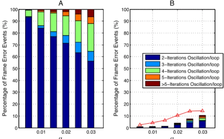
deterministic BF decoders [16] [24]. Indeed, when we consider the case of the GDBF, the failure comes from the fact that, during the decoding process, GDBF decoder falls into the infinite oscillations (or loops) between the tentative states of v, which prevent GDBF converging to the correct codeword [14] [16]. The probabilistic flip of PPBF helps break this oscillation and thus helps it converge. For illustration, we conducted a statistical analysis on the failures of GDBF decoder and the oscillation breaking of PPBF on the Tanner code. The results are plotted in Fig. 2. In Fig. 2A, we classified all the failure cases of GDBF into the t-iterations oscillation types, i.e., the positions of erroneous bits repeat the same after t iterations, v(k+t) = v(k), for several values of α and Itmax = 300.
It is confirmed by Fig. 2A that, all of the decoding failures of GDBF are due to the infinite oscillation between states
of v and furthermore, the 2-iteration oscillations dominate
other types, especially in the low error rate region. We then re-decoded the GDBF failure cases by PPBF (and also by PGDBF for comparison). The results are plotted in Fig. 2B. It is remarked that, the PPBF corrects almost the failure cases of GDBF, especially in low error rate region. This above interesting property is the source of PPBF error correction improvement. 0.01 0.02 0.03 0 10 20 30 40 50 60 70 80 90 100 α
Percentage of Frame Error Events (%)
A 0.01 0.02 0.03 0 10 20 30 40 50 60 70 80 90 100 α
Percentage of Frame Error Events (%)
B 2−Iterations Oscillation/loop 3−Iterations Oscillation/loop 4−Iterations Oscillation/loop 5−Iterations Oscillation/loop >5−Iterations Oscillation/loop
Fig. 2: The statistical analysis of decoding failure of BF decoders on the Tanner code: A. The failure types of GDBF decoder, B. The remaining after re-decoding the failure code-words in (A) by PPBF (bars) and by PGDBF (red triangle-marked curve).
v
2v
5v
4v
1v
3v
5v
4v
1v
2v
3A
B
y
5y
4y
1y
3y
2y
5y
4y
1y
3y
2Fig. 3: An example of error pattern with which PGDBF failed to correct while PPBF can correct.
The error correction of PPBF in the above statistics is even better than that of the PGDBF decoder. This is because of the fact that, there are certain error patterns with which PGDBF failed to correct while PPBF succeeds. We show an example
of these error patterns in Fig. 3 where there are 4 bits in
error allocated in a Trapping Set (5, 3) [14]. Fig. 3A describes the error positions initially received from the channel. The correct VNs (satisfied CNs) are denoted as white-filled circles (squares), the erroneous VNs (unsatisfied CNs) are the black-filled circles (squares). The smaller cycles denote the channel values of each VN. When decoding this error pattern by
PGDBF decoder, the VN v5 has maximum energy (E5(1)= 2)
(other VNs have energy of1) and v5becomes the only flipping
candidate. The PGDBF will either flip v5(ifR(1)5 = 1) or not
flip v5 (if R(1)5 = 0). In the latter case, PGDBF keeps the
same error pattern for the next iteration. In the case PGDBF flipsv5, the error locations are illustrated in Fig. 3B and in the
has energy of 2 while others have either 1 or 0. The PGDBF may again flip or not flip v5 depending on R(2)5 . Therefore,
the PGDBF is trapped in the 2-iteration oscillation and never
correct all erroneous VNs due to its maximum-energy VN flip constraint. On the contrary, in the case of PPBF, all VNs are the flipping candidates. With the above error pattern, at the first iteration, the PPBF not only flips v5 with p(2) (because
E5(1) = 2) but also other erroneous VNs (v1, v2, v3 and v4)
with p(1) > 0 (because E1(1) = E (1) 2 = E (1) 3 = E (1) 4 = 1).
For example, PPBF can correct this error pattern in a single iteration with probability(p(1))4(1−p(2)) > 0 where it flips 4
erroneous energy-1 VNs and does not flip other VNs. Using the analysis method in [24], it is shown that PPBF will eventually correct this error pattern in a subsequent number of iterations.
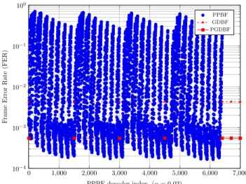
0 1,000 2,000 3,000 4,000 5,000 6,000 7,000 10−4 10−3 10−2 10−1 100 PPBF decoder index, (α = 0.02) F rame Error Rate (FER) PPBF GDBF PGDBF
Fig. 4: The decoding performance of PPBF decoder with different values of p combined from Tab. I, on comparison to the GDBF and PGDBF (p = 0.7) on the Tanner code at
α = 0.02, Itmax= 300.
The PPBF error correction capability is controlled by the values of p. We show that, it is feasible to choose p such that PPBF provides the significant decoding gain, compared to PGDBF and GDBF, by the following experiment. A statistics on the Frame Error Rate (FER) as a function of p was
conducted on the Tanner code (dv = 3, dc = 5). The testing
values of p were chosen with the ranges and steps as in the table I and they are explained as following. It is obvious to
choose p0 = p(0) = 0 since the VN having all neighbor
CN satisfied and being similar to the channel received value, should not be flipped. In principle, the VN that has higher energy values should have higher probability of flip. The VN that has all neighbor CN unsatisfied and its value disagrees with the channel received value (in the Tanner code, its energy
is 4), should be flipped with high probability (p4 = p(4)
should be close to 1). The VN that has energy of 1 should
be flipped with a small probability (p1 = p(1) should be
close to0) to avoid flip too many correct VNs unintentionally since there may exist many correct VNs having the energy
of 1. p2 = p(2) and p3 = p(3) were chosen to cover a
large ranges. Table I shows all of the studied configurations. A nested loops are formed to cover all combinations where p1 is in the most inner loop,p4 is the most outer loop. There
are 6400 combinations and they are marked by an index i
(0 ≤ i ≤ 6399) from p[0]to p[6399]. We run the PPBF decoder
with those values of p[i] atα = 0.02, Itmax = 300 and plot
the results in Fig. 4. We also show the decoding performance of
GDBF and PGDBF decoders (also atα = 0.02, Itmax= 300)
to make the comparisons.
1 100 200 300 500 700 900 1000 10−7 10−6 10−5 10−4 10−3 10−2 10−1 100 Number of Iterations F rame Error Rate (FER) GDBF PGDBF PPBF
Fig. 5: FER of the proposed PPBF, the GDBF and PGDBF (p = 0.7) decoders as function of the number of decoding
iterations on the Tanner code forα = 0.01.
TABLE I: The probability ranges for the statistical experiment.
min max step number of testing cases
p0 0 0 0 1
p1 0 0.039 0.001 40
p2 0.1 0.5 0.1 5
p3 0.3 1.0 0.1 8
p4 0.7 1.0 0.1 4
Total testing cases 6400
It can be seen that, there are many values of p with which PPBF decoder outperforms PGDBF decoder. This number is even larger when comparing to the GDBF decoder. Some of
them may have 1.4 decade better than GDBF and 0.6 decade
better than PGDBF. The numerous options of p providing a good decoding performance, are very promising since they facilitate the choice of PPBF to have the good decoding performance and simplify the hardware implementation, as shown in Section IV.
It is observed that the performance of PPBF decoder is con-tinuously improved when increasing the number of decoding iterations. Indeed, as seen in Fig. 5 where we plot the FER as a function of the number of iterations, the PGDBF tends
to saturate in correcting errors after 200 decoding iterations
while the GDBF is saturated even after10 decoding iterations.
will not provide any gain in error correction. However, this is not the case of PPBF decoder which continues to decrease the
FER after the first 200 iterations. It can be seen that, when
PPBF runs up toItmax= 1000 iterations, the FER si reduced
around 1 decade compared to the one at 200 iterations. The
PPBF is, therefore, very favorable in the applications where error correction is more important than the decoding time constraint.
As a conclusion of this section, our statistical analysis reveals that PPBF is a very promising decoder in terms of error correction. It is even more interesting since PPBF is shown to improve significantly the decoding frequency when being implemented, which is presented in the next section. Some open research directions may be opened, e.g., the theoretical optimization and the systematic choice of p where it may be
considered as a function of α or even a function of decoding
iterations. PPBF may be optimized for the additive white gaussian noise (in which PPBF may converge to the Noisy GDBF in [27]) channel and/or on irregular LDPC codes. These interesting directions are kept for our future work.
D. The PPBF improves the decoding throughput and reduces the BF decoder complexity
Typically, the average decoding throughput of a hardware
implemented BF decoder, θ (in bits/s), is computed using the
Equ. 3 wherefmaxdenotes the maximum decoding frequency,
Nc denotes the number of clock cycles required for each
decoding iteration and Itave is the number of iterations in
average.
θ = N ∗ fmax
Itave∗ Nc
(3) In a hardware implemented LDPC decoder, the maximal operating frequency is limited by the length of the longest data path (and so-called, critical path) andfmaxshould be inferior
to1/tD, (fmax< 1/tD), wheretD is the length of the critical
path to avoid the timing error in run-time [25]. In order to
improve the decoding throughput (assuming keepingN , Itave
and Nc constant), the hardware implementations of LDPC
decoders tend to be parallelized to shorten the critical path [22], increasing maximally the achievable operating frequency
fmax. However, the maximization of the operating frequency
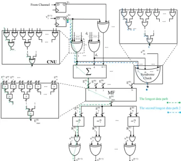
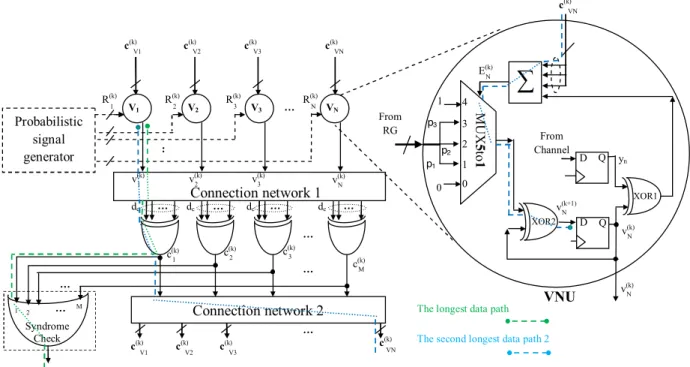
in some BF decoders reported in the literature, such as GDBF, PGDBF [14] or MBF [11] may be limited since the global op-eration still required in these decoders, dramatically increases the critical path [17]. In order to clarify the effect of the global operation on the critical path as well as the decoder complexity, we choose to analyze the architecture of PGDBF decoder in [14] (presented in Fig. 6). The operation of PGDBF decoder on this architecture may be found in that paper. The longest data path in PGDBF implementation is shown by the dashed green path in Fig. 6. This critical path starts from the output
of D Flip-Flop storing vn(k) and passes to the CN computing
unit (CNU), the energy computation (summation block), the Maximum Finder (MF block), several computing units and
ends at the input-D of theD Flip-Flop (the updated VN value
for the next iteration,v(k+1)n ). Many implementing methods of
XOR2 c(k) VN N v(k) 2 v(k) XOR2 XOR2 XOR2 XOR1 CNU 1 v(k) 1 R(k) 2 R(k) N R(k) … . 2 E(k) dv 1 E(k) 2 E(k) 1 v(k) y1 D Q D Q 1 From Channel ∑ 1 v(k+1) … . … . dc … . … . 1 dv dv+1 MF 1 2 3 3 E(k) N E(k) N … . =? 1 E(k) =? =? N E(k) … . … . … . : : > > > > > > > > > 1 E(k) 2 E(k) 3 E(k) … . EN (k) max E(k) max E(k) … . … . M c(k) … . … . 1 dv … M . … . … . : : : : : … . … . … .
The longest data path
The second longest data path 2
Syndrome Check 1 v(k+1) 2 v(k+1) N v(k+1) … .
Fig. 6: The critical paths in PGDBF decoder.
the MF can be found in [17]. We illustrate the implementation of MF in Fig. 6 by the binary tree of the Compare-And-Swap Units (CASUs) [11]. The CASU passes at its output the larger
value of the2 input values. The latency of the MF module can
be formulated astM F = tcdlog2(N )e where tc is the delay of
a single CASU module. This critical path may become longer when longer code is used. The ASIC synthesis results of the
PGDBF decoder on the dv = 3, dc= 6, N = 1296, M = 648,
code rate R = 0.50 regular LDPC code [22] (denoted as
dv3R050N1296) show that, the MF occupies more than 40%
of the total length of the critical path (the details of synthesis setup are introduced in section V). The MF is also a large part of PGDBF in terms of complexity since it requires
approximately N − 1 CASUs. The synthesis shows also that,
the MF is responsible for 20% of the total PGDBF decoder
area.
The VNs of PPBF do not require the maximum energy value for their operations. This is the source of the improvement in the terms of operating frequency of PPBF. For example, it
is expected that, PPBF will reduce the critical path by 40%
when designed and synthesized on the same dv3R050N1296 LDPC code. Since the MF is not implemented, the decoder complexity will be reduced, compared to that of the PGDBF.
III. THENON-SYNDROMEPROBABILISTICPARALLELBIT
FLIPPINGDECODER
The PPBF is expected to improve the operating frequency since the critical path is significantly reduced (as proven by the synthesis results in Section V). In the synthesized PPBF decoder, it is observed that, the critical path of PPBF starts from the output of the D Flip-Flop storing v(k)n and passes to
(which controls the enable-input ofD Flip-Flop to store vn(k+1)
into the place of v(k)n ). This critical path is similar to the
second longest data path in PGDBF implementation illustrated in Fig. 6 by the dashed blue path. We target improving the operating frequency of the PPBF by eliminating the SC module from the data path and shortening the critical path of PPBF. This modified version of PPBF is named as NS-PPBF decoder. In some LDPC decoding algorithms such as MS, OMS, Sum-Product or Gallager-A/B, the decoding process may continue to run when the decoder already converges to the correct codeword. This extra updating of the A-Posteriori-Probability (APP) will make the hard-decision even more solid. This property provides the possibilities that, the early stopping condition (the SC module) may not be needed. The situation is different in the case of BF decoders such as GDBF, PGDBF, PPBF etc. where the SC module plays an important role in ensuring the finding of correct codewords. Indeed, when converging to the correct codeword (all CN values are zeros),
the computed energy in these BF decoders is either 0 (of the
correctly received VNs from channel) or 1 (of the incorrectly
received VNs from channel, the value of1 comes from the term
v(k)n ⊕ yn in energy computation of Equ. 2). If the SC result is
not verified to stop the decoding process, the BF decoders tend to flip the energy-1 VNs in the next iteration (Note that the GDBF will flip all energy-1 VNs while PPBF and PGDBF flip a random part of them). These decoders are re-entering to the incorrect-codeword states and the correct codeword may not
be found after Itmax iterations or in a subsequent number of
iterations after converging. Because of this flipping principle, the SC is inevitable when implementing these BF decoders (note further that, since the computations are simple, in the literature, these BF decoders are usually implemented such that
they take only Nc = 1 clock cycle for 1 decoding iteration).
In the PPBF, the SC module becomes a part of the critical path. Moreover, the SC is a global operation which verifies all the values ofM CNs in each iteration. It occupies, therefore, a noticeable part of that critical path in PPBF. In fact, the SC introduces a delays of tSC = todlog2(M )e, where to is
the delay of a single OR gate, when implemented as a binary tree of OR gates (as in Fig. 6). The hardware synthesis of
PPBF shows that the delay of SC module is around 20% of
the PPBF critical path length. Our proposed NS-PPBF decoder introduces a new stopping mechanism which does not depend on the SC result.
Algorithm 3 The VN operations of the NS-PPBF decoder
1: for1 ≤ n ≤ N do . VN processing
2: Compute E(k)n , using Equ. (2).
3: if En(k)6= 1 orvn(k)= yn then
4: Generate R(k)n from B(p(En(k))).
5: ifR(k)n = 1 then
6: vn(k+1)= v(k)n ⊕ 1
7: end if
8: end if
9: end for
The proposed flipping mechanism targets to automatically stop flipping the VNs when the correct codeword are found, i.e., all the CNs are satisfied (all CNs are 0’s). The VN operation of NS-PPBF is described in Algorithm 3. It can be seen that, the flipping of NS-PPBF decoder is almost similar to that of the PPBF decoder and the difference is on the
flipping when the VN energy is 1. In fact, it is sufficient to
additionally manipulate on the case that En(k) = 1 because
when the codeword is found, the VN produces only the values 1 or 0 as its energy, and the energy-0 VNs are not flipped
since p0 = 0. In NS-PPBF, when the energy En(k) = 1, it
separates the case where the value1 is obtained from the term
v(k)n ⊕ yn and the case where the value 1 is obtained from
the term P
cm∈N (vn)c
(k)
m. NS-PPBF then flips the VN having
E(k)n = 1 with probability p1= p(1) only in the latter case. It
means that, NS-PPBF will not flip the VNs having energy 1
coming from the disagreement between the current value and the channel value. By using this principle, whenever a correct codeword is found, all the CNs are satisfied, the NS-PPBF
will not flip any VNs and the current v(k) is preserved. The
decoding process will stop either when Itmax iterations have
been reached (if the SC is not implemented), or the parallelized
implemented SC produces the stopping signal. v(k) is then
declared as the decoded codeword.
It can be seen that, the NS-PPBF decoding process will terminate without using the signal from the SC module. The SC contribution to the critical path have been eliminated, which will improve the operating frequency of the decoder. However, the constraint applied on the energy-1 VNs reduces the decoding dynamics and may lead to degradation in error correction, compared to the PPBF decoder. We observed that the performance degradation depends on the existence of the small and “harmful” sub-graphs in the Tanner graph e.g., The trapping set (5,3) in the Tanner code, which prevent the decoding convergence. We show an example as in Fig. 7 where Fig. 7A shows the channel error configuration. Decoding this error configuration may leads to a special state as in Fig. 7B where all VNs in the TS(5,3) are erroneous. It can be seen that, this is a trapping state since flipping any bits out of this TS will not increase the energy of the VN in the TS. In other words, only flipping the VNs in the TS helps escape from this
state and converge. With the PPBF, all 5 VNs have flipping
probability p1 while only v2, v4 and v5 may be flipped in
the case of the NS-PPBF. This reduces the decoding success chance of NS-PPBF. In fact, decoding this error configuration
by the PPBF and NS-PPBF with p = (0, 0.0081, 0.3, 0.7, 1)
produces FER of 4.2e−3 and2.58e−2, respectively.
IV. THEHARDWAREARCHITECTURE
In order to verify the efficiency of the proposed BF decoders in terms of decoding frequency and complexity, the hardware architectures implementing these decoders are introduced in this section. These hardware architectures are then synthesized on the Application-Specific Integrated Circuit (ASIC). The synthesis results and discussions are presented in the next section.
8
1
R
(k):
…. dcR
(k):
v
5v
4v
1v
2v
3v
5v
4v
1v
2v
3A
B
….
R
t 1 2 ..S p2Cross-bar network
p1 p3 p1 p2 p3 p1 p2 p3 PCU N R(k) 2 R(k) 1 R(k)Fig. 7: An example of error pattern where the PPBF has higher probability to correct than the NS-PPBF: (A) the error configuration received from channel, (B) a trapping state during the decoding process.
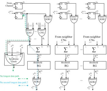
The first proposed hardware architecture of the PPBF de-coder is presented in Fig. 8. Similarly to the architecture of
PGDBF decoder, the CN operations is realized by the dc
-input XOR gates. The VN energy value is computed by the summation block whose inputs are the CN computation results and the XOR1 (computing the term vn(k)⊕yn). The key feature
of this architecture is that the computed energy values controls the threshold input of a random generator (RG). This threshold input is used to control the probability of the generated bit and by doing that, the probability of the generated bit is adapted for each VN and each iteration. One RG method could be used is the Linear Feedback Shift Register (LFSR) as in [18]. The VN value for the next iteration,v(k+1)n , is computed by the XOR2
gate based on the generated bit and the VN current valuev(k)n .
Thev(k+1)n is an inversion ofvn(k)if the generated bitRn(k)= 1
since X ⊕ 1 = NOT(X), ∀X. When the generated bitR(k)n = 0,
v(k+1)n = v(k)n since X ⊕ 0 = X, ∀X. The SC module is
implemented to stop the decoder when the correct codeword is found. This architecture can fully execute the operations of the PPBF decoder and can also be adapted for the NS-PPBF. However, the results reported in [18] revealed that, this method may be costly since each VN requires an LFSR module and the decoder complexity may be increased due to these RGs,
especially when the LDPC code with large N is used. We
leave aside this architecture and focus on a low-complexity solution to generate the binary random signals, introduced in [14], called Cyclic Shift Truncated Sequence (CSTS). A. The probabilistic signal generator for PPBF and NS-PPBF decoders
Inspired by the results of [14] where the correlation in the random generation may not much affect the error correction of the probabilistic BF decoders, we apply that CSTS approach to implement the RGs for PPBF and NS-PPBF decoders, to
reduce the hardware resources. In the CSTS, a short D
Flip-Flop sequence, Rt with size |Rt| = S < N , is allocated. Rt
initially stores the generated bits where the 1’s are with the
ratio of pr on the total of bits, and they are distributed in an
arbitrary order. For each clock cycle, Rt is cyclically shifted.
It can be approximated that in S clock cycles each output of
Rtproduces the bits 1 with probability pr. The outputs of D
Flip-Flops in Rt are used as a random bit, triggered to the
Variable Node Processing Units (VNUs) and one output can
2 E(k) =? 1 E(k) =? =? N E(k) … . 2 v(k+1) N v(k+1) … . 2 v(k) N v(k) 2 R(k) … . 1 v(k) 1 v(k) R1 (k) … . dv 1 E(k) y1 D Q D Q 1 From Channel
∑
1 v(k+1) … . … . dc … . … . 1 dv dv+1 M c(k) 1 dv … M . Syndrome Check 1 v(k+1) RG threshold 2 v(k) 2 E(k)∑
1 dv dv+1 … . RG threshold 2 v(k+1) … . … . … . 2 v(k) y2 D Q D Q 2 v(k+1) … . From neighbor CNs N v(k) RN (k) N E(k)∑
1 dv dv+1 RG threshold N v(k+1) N v(k) yN D Q D Q N v(k+1) … . From neighbor CNs XOR1 XOR1 XOR1XOR2 XOR2 XOR2
2 c(k) 1 c(k) CNU CNU
The longest data path
The second longest data path 2
Fig. 8: The LFSR-based implementation of PPBF decoder.
1 R(k) : … . dc R(k): v5 v4 v1 v2 v3 v5 v4 v1 v2 v3 A B …. Rt 1 2 .. S p2 Cross-bar network p1 p3 p1 p2 p3 p1 p2 p3 PCU N R(k) 2 R(k) 1 R(k) …. Rt 1 2 .. S p2 Cross-bar network p1 p3 p1 p2 p3 p1 p2 p3 PCU N R(k) 2 R(k) 1 R(k)
Fig. 9: The proposed probabilistic signal generator (random generator - RG) for PPBF decoder.
be used for multiple VNUs of the PGDBF without degrading the decoding performance [14].
The RGs of the PPBF and NS-PPBF decoders are required to generate the random bits with different probabilities. In order to produce these desired probabilities, we use the logic gates as introduced in [18] and its principle is briefly recapitulated
as follows. Let a and b be two independent random binary
variables with Pr(a = 1) = pr and Pr(b = 1) = pr. It can
be shown that, Pr((a AND b) = 1) = p2
r, Pr(NOT(a) =
1) = 1 − pr and Pr((a OR b) = 1) = 2pr − p2r. Other
logic functions such as XOR etc. can also be formulated. We design the Probability Controlling Units (PCUs), composed by the logic gates, to produce the random bits for our PPBF and
NS-PPBF decoders. The PCU has the binary values fromRtas
its inputs through the crossbar network and has several binary
outputs. Each output has different probability to be 1, which
is transformed from the probability pr fromRt.
In this paper, we target to implement PPBF and NS-PPBF decoders for the Tanner and the dv3R050N1296 LDPC codes
with dv = 3. The extension for other LDPC codes which
MUX 5to 1 MUX 5d to 1 N v(k) p1 0 … . N R(k) Connection network 2 yn VV11,1 … . … . … . … . VV21,1 VV31,1 dc dc dc dc VVN1,1 D Q 0 D Q XOR2 XOR1 N v(k) VNU 1 v(k) 2 v(k) 3 v(k) N v(k) 1 c(k) 2 c(k) 3 c(k) M c(k) Probabilistic signal generator From Channel 1 2 3 4 1
∑
c(k) VN N v(k+1) c(k) V1 c(k) V2 c(k) V3 c(k) VN c(k) V1 … . c(k) V2 c(k) V3 c(k) VN : 3 R(k) 2 R(k) 1 R(k) p2 p3 … . From RG 0 1 0 N E(k) Connection network 1The longest data path
The second longest data path 2
The longest data path
The second longest data path 2 c(k) VN … . N R(k) Connection network 2 N v(k) yn VV11,1 … . … . … . … . VV21,1 VV31,1 dc dc dc dc VVN1 D Q 0 D Q XOR2 XOR1 N v(k) VNU N E(k) 1 v(k) 2 v(k) 3 v(k) N v(k) 1 c(k) 2 c(k) 3 c(k) M c(k) Probabilistic signal generator From Channel 1 2 3 4 0 1
∑
N v(k+1) c(k) V1 c(k) V2 c(k) V3 c(k) VN c(k) V1 … . c(k) V2 c(k) V3 c(k) VN : 3 R(k) 2 R(k) 1 R(k) p2 p1 p3 … . From RG … . 1 2 … M . Syndrome Check … . Connection network 1 MUX 5to 1Fig. 10: The proposed architecture for the realization of PPBF decoder fordv= 3 LDPC codes.
shown in the statistical analysis, several values of p may be used to provide good decoding performance gain. We use p= (0, 0.0081, 0.3, 0.7, 1) as an example to implement since it provides a good error correction while facilitating the hardware implementation. In fact, it can be shown that this particular p is equal to(0, p4
r, pr, 1 − pr, 1) where pr= 0.3 . The designed
RG is shown in Fig. 9 where N PCUs are designed for N
VNs. Each PCU has dv= 3 outputs (internally named as p1,
p2andp3). The outputs have the value of1 with the probability
correspondingly to p1, p2 and p3. The outputs of each PCU
are triggered to the corresponding implemented VNU of the PPBF and NS-PPBF, presented in the next section.
B. The computing units of PPBF decoder
PPBF decoder is realized in hardware by two connection networks connecting two groups of processing units: the VNUs and CNUs. The proposed architecture to implement PPBF
decoder is presented in Fig. 10. The connection network 1
transmits the messages from VNUs to CNUs and the
con-nection network 2 is to transfer the messages from CNUs to
VNUs. The CNUs in PPBF decoder are also the dc-inputs
XOR gates, computing the parity check on the VN messages. The CNUs outputs are transmitted to the VNUs inputs and
we denote (as in Fig. 10) cvn as the group of messages of
cm ∈ N (vn), 1 ≤ n ≤ N . In each VNU, the summation
block computes the VN energy value and this computed energy controls the selection of the multiplexer MUX5to1 module. The MUX5to1 module is a key module which results to flip or not the VN current value, v(k)n , by producing 1s or 0s at
its output. When the output of MUX5to1 is1, the VN current
value, v(k)n , is XOR-ed by 1 by the XOR2 and is flipped,
otherwise, vn(k+1)= vn(k)⊕ 0 = vn(k). The flipping probability
ofv(k)n is, therefore, controlled by its energy. Indeed, the input
0 of MUX5to1 is always reset to 0 while the input 4 is set
to 1 which results the fact that, the VN which has energy of
0 is not flipped and the VN having energy of 4 is flipped
with probability of 1. When the energy is from 1 to 3, the
corresponding flipping probability is arranged asp1,p2andp3,
controlled by the RG. The SC is implemented byM -inputs OR
gate whose inputs are the outputs of the CNUs. The decoder
will stop when SC produces0.
It should be noted that, this PPBF architecture requiresNc=
1 clock cycle for each decoding iteration. The critical path of the PPBF is denoted by the dashed green path and the second longest data path is shown by the dashed blue path in Fig. 10.
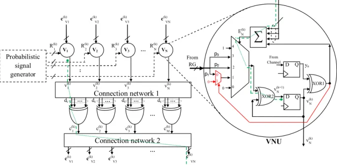
C. The computing units of NS-PPBF decoder
The implementation architecture of NS-PPBF decoder is presented in Fig. 11, which follows mostly the principle of PPBF architecture. The difference comes from the added multiplexer MUX2to1. The MUX2to1 is controlled by the output of the XOR1 which indicates the similarity between the v(k)n andyn. This added MUX2to1 contributes to the flipping
feature of NS-PPBF in the case when the energy-1 appears. In fact, when En(k)= 1 and v(k)n differs fromyn, XOR2 always
receives0’s from MUX5to1 and v(k)n will not be flipped. When
E(k)n = 1 and vn(k) equals to yn, XOR2 receives signal from
10 … . N R(k) Connection network 2 N v(k) yn VV11,1 … . … . … . … . VV21,1 VV31,1 dc dc dc dc VVN1 D Q 0 D Q XOR2 XOR1 N v(k) VNU N E(k) 1 v(k) 2 v(k) 3 v(k) N v(k) 1 c(k) 2 c(k) 3 c(k) M c(k) Probabilistic signal generator From Channel 1 2 3 4 0 1
∑
N v(k+1) c(k) V1 c(k) V2 c(k) V3 c(k) VN c(k) V1 … . c(k) V2 c(k) V3 c(k) VN : 3 R(k) 2 R(k) 1 R(k) p2 p1 p3 … . From RG … . 1 2 … M . Syndrome Check … . Connection network 1 MUX 5to 1 MUX 5to 1 MUX 5d to 1 N v(k) p1 0 … . N R(k) Connection network 2 yn VV11,1 … . … . … . … . VV21,1 VV31,1 dc dc dc dc VVN1,1 D Q 0 D Q XOR2 XOR1 N v(k) VNU 1 v(k) 2 v(k) 3 v(k) N v(k) 1 c(k) 2 c(k) 3 c(k) M c(k) Probabilistic signal generator From Channel 1 2 3 4 1∑
c(k) VN N v(k+1) c(k) V1 c(k) V2 c(k) V3 c(k) VN c(k) V1 … . c(k) V2 c(k) V3 c(k) VN : 3 R(k) 2 R(k) 1 R(k) p2 p3 … . From RG 0 1 0 N E(k) Connection network 1Fig. 11: The proposed architecture for the realization of NS-PPBF decoder fordv= 3 LDPC codes.
In the NS-PPBF hardware architecture, the SC is not
imple-mented and the decoder will stop after Itmax iterations. The
critical path of NS-PPBF in the synthesized decoder is shown by the dashed green path in Fig. 11.
V. SYNTHESIS RESULTS AND DECODING PERFORMANCE
A. Synthesis results
In this section, we report the ASIC synthesis results of our decoder implementations. The proposed decoders are imple-mented using the Digital Standard Cell Library
SAED-EDK90-CORE, Process 1P9M 1.2v/2.5v. The hierarchical design flow
is followed with the Synopsys Design Platform: Synopsys Design Compiler is used for VHDL synthesis, Synopsys VCS tool for simulation and DVE, a graphical user interface for debugging and viewing waveforms. Synopsys Prime Time tool is used for timing analysis, power and energy estimation. We generate the switching activity interchange format (saif) file to estimate the power consumption of the decoders. The Synopsys IC Compiler (ICC) is used for floor planning, place and route. We make the first synthesis of our decoders on the Tanner
code (dv = 3, dc = 5, N = 155, M = 93). Our strategy
is to look for the minimum timing constraint to which the synthesizer can pass (which indicates the maximum achievable frequency that the decoders can reach) after place-and-route synthesizing processing. The GDBF and PGDBF decoders are implemented following the architecture described in [14]. The synthesis results are reported in Table II. It can be seen, as
expected, that PPBF increases more than 43% the operating
frequency compared to GDBF and PGDBF while NS-PPBF
is even more than 64%. The average decoding throughput
at α = 0.012 is also provided. It is shown that, the PPBF
Fig. 12: Layout plot of the PPBF decoder implemented in Table III.
and NS-PPBF are faster in decoding speed than PGDBF
(with 28.1 Gbps and 32.5 Gbps compared to 25.3 Gbps). In
terms of hardware complexity, PPBF reduces 3.4% and
NS-PPBF reduces1.4% compared to the PGDBF. This complexity
reduction is interesting since PPBF and NS-PPBF provide a better error correction (shown in the next sub-section) while requiring less hardware resources. The complexity reduction is modest because of the fact that, the RGs are more costly than that of the PGDBF, which diminishes the advantage of the MF removal. Our decoders consume more energy than other
BF decoders. PPBF needs 0.59 pJ to decode 1 bit while
NS-PPBF requires 0.6 pJ, compared to 0.33 pJ of PGDBF and
0.24 pJ of GDBF. It is because of the fact that, the proposed decoders operate at higher frequency. Also, more switching activities may be produced in PPBF and NS-PPBF due to the randomness injection in all levels of VN energy.
In the second synthesis, we implement the proposed de-coders for the longer code (the dv3R050N1296 LDPC code).
TABLE II: The synthesis results of PPBF and NS-PPBF in the comparisons to GDBF and PGDBF decoders on the Tanner Code. All the RGs are the CSTS-based implementations with S = 155. PGDBF is with p = 0.7. The average throughput θ and the average power consumption (energy/bit) are computed
atα = 0.012. Area(µm2 ) fmax(MHz) θ (Gbps) Energy/bit (pJ) GDBF 39528 (-17.6%) 435 (+0%) 30.4 0.24 PGDBF 46472 (-0.0%) 435 (+0%) 25.2 0.33 PPBF 44881 (-3.4%) 625 (+43.7%) 28.1 0.59 NS-PPBF 45814 (-1.4%) 714 (+64.1%) 32.5(*) 0.60(*)
0.369@Itmax 53.18@Itmax (*)Since the SC module is not implemented in this NS-PPBF implementation, these average
values of NS-PPBF are bounds on the achievable results and they are not really practical relevance.
TABLE III: The synthesis results of the implemented PPBF and NS-PPBF decoders on dv3R050N1296: area percentage of computing units. The implemented layout of the PPBF is shown is Fig. 12. PPBF NS-PPBF Operating temperature 25◦C Operating voltage 1.2V Total area (mm2) 0.367 0.349 Frequency (Mhz) 476 556 CNU 14.2% 17.3% VNU 67.0% 65.0% Input buffer 13.7% 13.4% Random Generator 4.0% 3.9%
Syndrome Check 0.7% N/A
Controller 0.4% 0.4%
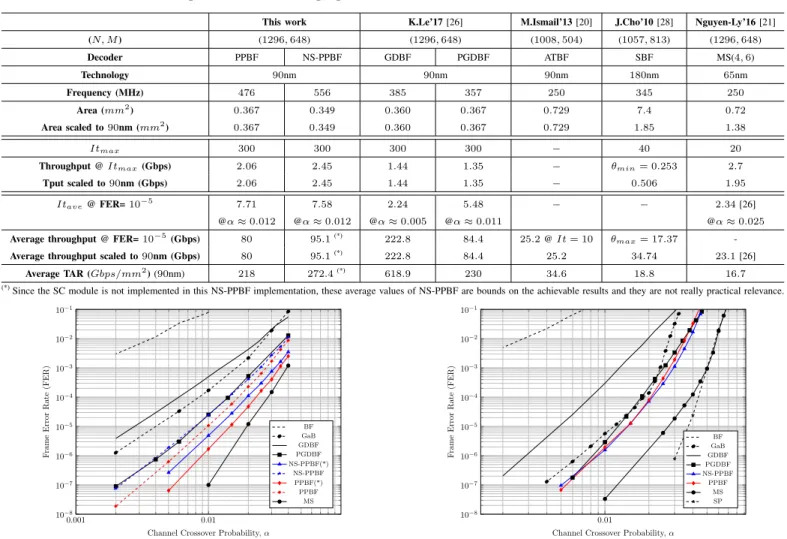
We present the detailed complexity of the computing units of PPBF and NS-PPBF decoders in table III. Further comparisons of the proposed decoders with other BF-based decoders as well as the MS benchmark from the literature are shown in table IV. It can be seen in the table IV that, PPBF and NS-PPBF provide a significant gain in decoding frequency. PPBF can operate
at fmax = 476MHz and NS-PPBF is at fmax = 556MHz,
compared to 385MHz of GDBF and 357MHz of PGDBF.
PPBF and NS-PPBF are much faster than MS (250MHz) and ATBF (250MHz). In terms of hardware complexity, the proposed decoders require small hardware resource to be
implemented. The required area is from0.35−0.37mm2which
is equivalent to that of the GDBF (and PGDBF) decoder. It
is only 1/5 of SBF, 1/4 of MS and 1/2 of ATBF decoders.
In terms of decoding throughput, we compute θ in the worst
case (where Itmax is used) and in the average case (where
Itave at F ER = 10−5 is used). In the former case, the
proposed decoders provide the throughput from2 to 2.5 Gbps
which are higher than the GDBF (1.44 Gbps), PGDBF (1.35 Gbps) and MS (1.95 Gbps). The better decoding throughput is also observed in the average throughput to maintain the FER
at 10−5. In order to make the comparison in the hardware
efficiency, we compute the throughput area ratio (TAR) for all the synthesis results and make comparison to other decoders. It can be seen that, the TAR of PPBF and NS-PPBF (218−272
Gbps/mm2) are much higher than the other decoders such as
ATBF (34.6 Gbps/mm2), SBF (18.8 Gbps/mm2) and MS
(16.7 Gbps/mm2) .
B. Decoding performance
The decoding performance of the PPBF and NS-PPBF decoders, simulated on several LDPC codes, is shown in this section. The values of p are chosen by empirical experiments. On the illustrating figures, we show the decoding performance comparisons with other hard decision decoders such as the conventional BF, GDBF, PGDBF (p = 0.7) and Gallager-B
(GaB). All hard decision decoders are run with Itmax= 300.
The simulations are run until 1000 error frames are found.
The performance of the quantized soft-decision MS decoder,
implemented in layered scheduling with4 bits for LLR
(Log-LikeLihood Ratio) and6 bits for A Posteriori Log-LikeLihood
Ratio (AP-LLR) [21], are also added, with the Itmax = 20.
We additionally compare the BF decoding performance to the
floating point sum-product (SP) decoding (Itmax= 20).
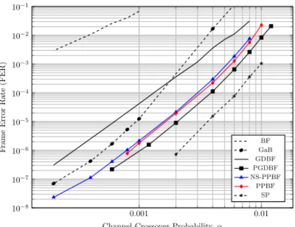
Fig. 13 shows the decoding performance on the Tanner code. It can be seen that, the PPBF is the best error correction compared to all other BF decoders. NS-PPBF is better than the PGDBF especially in the low-error rate region. With a small degradation compared to PPBF, NS-PPBF is at the gains of decoding throughput as shown in the previous section. We also extend the simulation of PPBF and NS-PPBF on this Tanner
code to run up to Itmax = 1000. Our proposed decoders
provide a significant gain in the decoding performance as
shown in the statistical analysis. Atα = 0.004, PPBF provides
around 2 decades gain in FER compared to PGDBF, 3.3
decades when compared to GDBF. WithItmax= 1000, PPBF
gains around 1 decade in FER when compared to itself with
Itmax= 300, which confirms the superiority of PPBF when
increasing the number of decoding iterations. It is also shown that, the decoding performance of PPBF and NS-PPBF is very close to that of the MS decoder.
The decoding performance on other LDPC codes with different (VN and CN) node degrees and code rates, are shown in Fig. 14, 15 and 16. Fig. 14 shows the performance on
the dv3R050N1298 (dv = 3, dc = 6, N = 1296, code rate
R = 0.5) LDPC code. With the chosen value of p, PPBF and NS-PPBF have the equivalent error correction and they are
better than PGDBF when FER > 1e−5. Compared to GDBF
decoder, PPBF and NS-PPBF provide a significant gain in performance, half-way approaching the MS, while requiring the equivalent hardware complexity and 1.5 times faster in decoding speed, as shown in the previous section.
The good decoding performance of PPBF and NS-PPBF
are also observed on dv = 3, dc = 6, N = 1296, code rate
R = 0.75 code (Fig. 15) and dv = 4, dc= 8, N = 1296, code
rate R = 0.5 (Fig. 16). Especially, PPBF and NS-PPBF are
very close to the MS performance for the latter code.
VI. CONCLUSION
In this paper, we propose a new high-throughput, low-complexity Bit Flipping decoder for Low-Density Parity-Check (LDPC) codes on Binary Symmetric Channel (BSC),
TABLE IV: Comparison between the proposed BF decoders and the state-of-the-art LDPC decoders.
This work K.Le’17 [26] M.Ismail’13 [20] J.Cho’10 [28] Nguyen-Ly’16 [21]
(N, M ) (1296, 648) (1296, 648) (1008, 504) (1057, 813) (1296, 648) Decoder PPBF NS-PPBF GDBF PGDBF ATBF SBF MS(4, 6) Technology 90nm 90nm 90nm 180nm 65nm Frequency (MHz) 476 556 385 357 250 345 250 Area (mm2) 0.367 0.349 0.360 0.367 0.729 7.4 0.72 Area scaled to90nm (mm2) 0.367 0.349 0.360 0.367 0.729 1.85 1.38 Itmax 300 300 300 300 − 40 20
Throughput @ Itmax(Gbps) 2.06 2.45 1.44 1.35 − θmin= 0.253 2.7
Tput scaled to90nm (Gbps) 2.06 2.45 1.44 1.35 − 0.506 1.95
Itave@ FER=10−5 7.71 7.58 2.24 5.48 − − 2.34 [26]
@α≈ 0.012 @α≈ 0.012 @α≈ 0.005 @α≈ 0.011 @α≈ 0.025
Average throughput @ FER=10−5(Gbps) 80 95.1(*)
222.8 84.4 25.2 @ It = 10 θmax= 17.37
-Average throughput scaled to90nm (Gbps) 80 95.1(*)
222.8 84.4 25.2 34.74 23.1 [26]
Average TAR (Gbps/mm2
) (90nm) 218 272.4(*)
618.9 230 34.6 18.8 16.7
(*)Since the SC module is not implemented in this NS-PPBF implementation, these average values of NS-PPBF are bounds on the achievable results and they are not really practical relevance.
0.001 0.01 10−8 10−7 10−6 10−5 10−4 10−3 10−2 10−1
Channel Crossover Probability, α
F rame Error Rate (FER) BF GaB GDBF PGDBF NS-PPBF(*) NS-PPBF PPBF(*) PPBF MS
Fig. 13: The decoding performance of the PPBF and the
NS-PPBF with p = (0, 0.0081, 0.3, 0.7, 1.0), on comparison to
other BF decoders and to the MS (Itmax= 20) on the Tanner
code. The curves with (*) are with Itmax = 1000 while the
others are withItmax= 300.
called Probabilistic Parallel Bit Flipping (PPBF). The PPBF is more advantageous than other state-of-the-art BF decoders such as the Gradient Descent Bit Flipping and Probabilistic Gradient Descent Bit Flipping decoders, in terms of operating frequency and decoder complexity, thanks to the elimination of the global operation which helps shorten the critical path and reduce the decoder hardware cost. Furthermore, in PPBF, the probabilistic flipping of the Variable Node is introduced for all levels of its energy value rather than only on the maximum values as in PGDBF. PPBF provides, therefore, a very good error correction capability and in some cases, overcomes some error patterns with which PGDBF can not correct. One im-proved version of PPBF, named as non-syndrome Probabilistic Parallel Bit Flipping (NS-PPBF), is then introduced in which the critical path is further shortened by eliminating the global Syndrome Check module from the data path. The operating frequency of the NS-PPBF is heightened while a negligible error correction degradation observed, with respect to those of
0.01 10−8 10−7 10−6 10−5 10−4 10−3 10−2 10−1
Channel Crossover Probability, α
F rame Error Rate (FER) BF GaB GDBF PGDBF NS-PPBF PPBF MS SP
Fig. 14: The decoding performance of the PPBF and the
NS-PPBF with p = (0, 0.0081, 0.3, 0.7, 1.0), on comparison to
other BF decoders and to the MS (Itmax= 20), SP (Itmax=
20) on the dv = 3, dc = 6, N = 1296, code rate R = 0.5
LDPC code. All BF-based decoders are with Itmax= 300.
the PPBF. The hardware architectures to implement the PPBF and NS-PPBF decoders are introduced with the detailed cir-cuits of the random generator and computing units. The ASIC synthesis results of the proposed architectures re-confirm as ex-pected that, PPBF and NS-PPBF are high hardware-efficiency and high decoding throughput. The proposed PPBF and NS-PPBF appear as the very low-complexity, high throughput decoders with the significant improvement in error correction, which can be seen as the competitive candidates for the next communication and storage standards.
REFERENCES
[1] “Wireless Lan Medium Access Control and Physical Layer Specifica-tions: Enhancements for Higher Throughput, p802.11n/d3.07,” IEEE-802.11n, Mar. 2008.
0.001 0.01 10−8 10−7 10−6 10−5 10−4 10−3 10−2 10−1
Channel Crossover Probability, α
F rame Error Rate (FER) BF GaB GDBF PGDBF NS-PPBF PPBF SP
Fig. 15: The decoding performance of the PPBF and the
NS-PPBF with p = (0, 0.001, 0.1, 1.0, 1.0), on comparison
to other BF decoders and to the MS (Itmax = 20), SP
(Itmax = 20) on the dv = 3, dc = 12, N = 1296, code
rate R = 0.75 LDPC code. All BF-based decoders are with
Itmax= 300. 0.01 10−8 10−7 10−6 10−5 10−4 10−3 10−2 10−1
Channel Crossover Probability, α
F rame Error Rate (FER) BF GaB GDBF PGDBF NS-PPBF PPBF MS SP
Fig. 16: The decoding performance of the PPBF and the
NS-PPBF with p = (0, 0.001, 0.05, 0.3, 0.95, 0.95), on
compar-ison to other BF decoders and to the MS (Itmax = 20),
SP (Itmax = 20) on the dv = 4, dc = 8, N = 1296, code
rate R = 0.5 LDPC code. All BF-based decoders are with
Itmax= 300.
[2] “Local and Metropolitan Area Networks - part 16, IEEE std 802.16a-2003,” IEEE-802.16.
[3] D. Declercq, M. Fossorier, and E. Biglieri, “Channel Coding: Theory, Algorithms, and Applications,” Academic Press Library Mobile and Wireless Communications, Elsevier, ISBN: 978-0-12-396499-1, 2014. [4] R. G. Gallager, “Low Density Parity Check Codes,” MIT Press,
Cam-bridge, 1963, Research Monograph series, 1963.
[5] B. Unal, A. Akoglu, F. Ghaffari and B. Vasi´c, “Hardware Implementa-tion and Performance Analysis of Resource Efficient Probabilistic Hard Decision LDPC Decoders,” IEEE Transactions on Circuits and Systems I: Regular Papers, early access, 2018.
[6] “IEEE Standard for Information Technology - corrigendum 2: IEEE std 802.3an-2006 10GBase-t correction,” IEEE Std 802.3-2005/Cor 2-2007 (Corrigendum to IEEE Std 802.3-2005), Aug. 2007.
[7] S. Jeon and B. V. K. V. Kumar, “Performance and Complexity of 32
k-bit Binary LDPC Codes for Magnetic Recording Channels,” IEEE Transactions on Magnetics, vol. 46, no. 6, pp. 2244–2247, June 2010. [8] K. C. Ho, C. L. Chen, Y. C. Liao, H. C. Chang, and C. Y. Lee, “A 3.46 Gb/s (9141,8224) LDPC-based ECC Scheme and On-line Channel Estimation for Solid-State Drive Applications,” 2015 IEEE International Symposium on Circuits and Systems (ISCAS), pp. 1450– 1453, May 2015.
[9] G. Dong, N. Xie, and T. Zhang, “On the Use of Soft-Decision Error-Correction Codes NAND Flash Memory,” IEEE Transactions on Circuits and Systems I: Regular Papers, vol. 58, no. 2, pp. 429–439, Feb. 2011.
[10] “LDPC Codes for the Enhanced Mobile Broadband (eMBB)
Data Channel the 3GPP 5G New Radio,” [Online]. Available: http://www.3gpp.org/ftp/tsg ran/WG1 RL1/TSGR1 88/Report/. [11] J. Jung and I. C. Park, “Multi-Bit Flipping Decoding of LDPC Codes
for NAND Storage Systems,” IEEE Communications Letters, vol. 21, no. 5, pp. 1089-7798, May 2017.
[12] Y. Du, Q. Li, L. Shi, D. Zou, H. Jin, and C. J. Xue, “Reducing LDPC Soft Sensing Latency by Lightweight Data Refresh for Flash Read Performance Improvement,” 2017 54th ACM/EDAC/IEEE Design Automation Conference (DAC), pp. 1–6, TX,USA, June 2017. [13] O. A. Rasheed, P. Ivanis, and B. Vasi´c, “Fault-tolerant Probabilistic
Gradient-Descent Bit Flipping Decoder,” IEEE Communications Let-ters, vol. 18, no. 9, pp. 1487–1490, Sept. 2014.
[14] K. Le, F. Ghaffari, D. Declercq, and B. Vasi´c, “Efficient Hardware Implementation of Probabilistic Gradient Descent Bit-Flipping,” IEEE Transactions on Circuits and Systems I: Regular Papers, vol. 64, no. 4, pp. 906–917, April 2017.
[15] M. Tanner, D. Srkdhara, and T. Fuja, “A Class of Group-Structured LDPC Codes,” Proc. 5th Int. Symp. Commun. Theory App., July 2001. [16] D. Declercq, C. Winstead, B. Vasic, F. Ghaffari, P. Ivanis, and E. Boutil-lon, “Noise-aided Gradient Descent Bit-Flipping decoders Approaching Maximum Likelihood Decoding,” 2016 9th International Symposium on Turbo Codes and Iterative Information Processing (ISTC), pp. 300–304, Brest, France, Sept. 2016.
[17] B. Yuce, H. F. Ugurdag, S. Goren, and G. Dundar, “Fast and Efficient Circuit Topologies for Finding the Maximum of n k-bit Numbers,” IEEE Transactions on Computers, vol. 63, no. 8, pp. 1868-1881, Aug. 2014. [18] K. Le, D. Declercq, F. Ghaffari, C. Spagnol, E. Popovici, P. Ivanis, and B. Vas´ıc, “Efficient Realization of Probabilistic Gradient Descent Bit Flipping Decoders,” 2015 IEEE International Symposium on Circuits and Systems (ISCAS), pp. 1494-1497, Lisbon, Portugal, May 2015. [19] G. Sundararajan, “Noisy Gradient Descent Bit Flip Decoding of Low
Density Parity Check Codes: Algorithm and Implementation” Doctoral dissertation, Utah State University, Logan, Utah, 2016.
[20] M. Ismail, I. Ahmed, , and J. Coon, “Low Power Decoding of LDPC Codes,” ISRN Sensor Networks, vol. 2013, no. 650740, 2013. [21] T. T. Nguyen-Ly, T. Gupta, M. Pezzin, V. Savin, D. Declercq, and
S. Cotofana, “Flexible, Cost-Efficient, High-Throughput Architecture for Layered LDPC Decoders with Fully-Parallel Processing Units,” 2016 Euromicro Conference on Digital System Design (DSD), pp. 230– 237, Limassol, Cyprus, Aug. 2016.
[22] T. T. Nguyen-Ly, V. Savin, K. Le, D. Declercq, F. Ghaffari and O. Boncalo, “Analysis and Design of Cost-Effective, High-Throughput LDPC Decoders,” IEEE Transactions on Very Large Scale Integration (VLSI) Systems,, Vol. 26, No. 3, pp. 508-521, Mar. 2018.
[23] D. Declercq, V. Savin, O. Boncalo and F. Ghaffari, “An Imprecise Stopping Criterion Based on In-Between Layers Partial Syndromes,” IEEE Communications Letters, Vol. 22, No. 1, pp. 13?-16, Jan. 2018. [24] B. Vas´ıc, P. Ivanis, D. Declercq and K. Le , “Approaching Maximum
Likelihood Performance of LDPC Codes by Stochastic Resonance Noisy Iterative Decoders,” 2016 Information Theory and Applications Workshop (ITA), pp. 1-9, La Jolla, CA, 2016.
[25] F. Leduc-Primeau, F. R. Kschischang and W. J. Gross, “Modeling and Energy Optimization of LDPC Decoder Circuits with Timing
![Fig. 1: The evolution in term of decoding performance of BF decoders on the Tanner code [15].](https://thumb-eu.123doks.com/thumbv2/123doknet/11643995.307539/3.918.106.424.78.326/fig-evolution-term-decoding-performance-decoders-tanner-code.webp)