HAL Id: hal-01136425
https://hal.archives-ouvertes.fr/hal-01136425
Submitted on 27 Mar 2015
HAL is a multi-disciplinary open access
archive for the deposit and dissemination of
sci-entific research documents, whether they are
pub-lished or not. The documents may come from
teaching and research institutions in France or
abroad, or from public or private research centers.
L’archive ouverte pluridisciplinaire HAL, est
destinée au dépôt et à la diffusion de documents
scientifiques de niveau recherche, publiés ou non,
émanant des établissements d’enseignement et de
recherche français ou étrangers, des laboratoires
publics ou privés.
Beyond 25 Gbit/s directly modulated, directly detected
OFDM using channel flattening by a Fabry-Perot filter
Luiz Anet Neto, Mathilde Gay, Laurent Bramerie, Christophe Peucheret,
Yann Frignac, Jean-Claude Simon, Monique Thual, Michel Joindot,
Christophe Levallois, Cyril Paranthoen, et al.
To cite this version:
Luiz Anet Neto, Mathilde Gay, Laurent Bramerie, Christophe Peucheret, Yann Frignac, et al.. Beyond
25 Gbit/s directly modulated, directly detected OFDM using channel flattening by a Fabry-Perot
filter. Optical Fiber Communication Conference (OFC 2015), Mar 2015, Los Angeles, California,
United States. pp.M3J.5, �10.1364/OFC.2015.M3J.5�. �hal-01136425�
M3J.5.pdf OFC 2015 © OSA 2015
Beyond 25 Gbit/s Directly Modulated, Directly Detected
OFDM Using Channel Flattening by a Fabry-Perot Filter
L. Anet-Neto(1), M. Gay(1), L. Bramerie(1), C. Peucheret(1), Y. Frignac(2), J.-C. Simon(1), M. Thual(1),
M. Joindot(1), C. Levallois(1), C. Paranthoen(1), S. Joshi(3), N. Chimot(3), F. Lelarge(3), P. Chanclou(4) (1) UMR FOTON, CNRS, Université de Rennes 1, INSA-Rennes, 22305 Lannion, France
(2) Institut Télécom SudParis, CNRS SAMOVAR UMR 5157, 9 Rue Charles Fourier, 91011 Evry, France (3) III-V Lab, Route de Nozay, 91460 Marcoussis, France
(4) Orange Labs, 2 Avenue Pierre Marzin, 22307 Lannion, France anetneto@enssat.fr
Abstract: We experimentally demonstrate the joint use of OFDM and channel flattening effect
provided by a Fabry-Perot filter to allow higher than 25 Gbit/s direct intensity modulated, directly detected transmission over up to 75 km SSMF.
OCIS codes: (060.4510) Optical communications; (130.2035) Dispersion compensation devices.
1. Introduction
Direct intensity modulation with direct detection (DIMDD) is the simplest and cheapest approach to transmit information through an optical fiber. The downside of DIMDD, however, is the inter-symbol interference (ISI) created by fiber chromatic dispersion (CD) and laser chirp and the induced limitations to the channel capacity. Many solutions have been reported to address this issue, some of which refer specifically to the transmitter side. For instance, the principle of dispersion-supported transmission consists in searching a specific bias point that optimizes the balance between CD and the laser chirp parameters [1]. More recently, optical filtering has been investigated with interesting impacts on the optical signal extinction ratio (ER) and dispersion tolerance using ON-OFF keying (OOK) modulation [2, 3]. By exploiting the wavelength shift caused by the laser chirp, the principle of this approach consists in suppressing the part of the modulated spectrum associated to the “0” bits, thus increasing the optical ER. Nevertheless, the simple increase of the ER alone does not provide better robustness to CD, meaning that some other filter-related effects also affect the transmission. Indeed, it is shown in [4] that a flatter channel frequency response after direct-detection can be obtained with an unchirped fiber grating if the laser is properly detuned with respect to the filter. However, no follow-ups regarding the effects of such a channel on a modulated signal were provided.
In this work, we experimentally investigate if a similar effect can be obtained with an advanced modulation format. We use adaptively modulated orthogonal frequency division multiplexing (OFDM) to assess the benefits brought by a Fabry-Perot (FP) filter to the DIMDD channel thanks to bit and power loading algorithms. In contrast with the numerical study reported with a super-Gaussian filter in [5], we use a larger signal bandwidth (10 GHz) with a higher number of subcarriers. This allows us to use the performance indicators of the OFDM subcarriers to assess the impact of the filter on the channel frequency response. In addition, we compare those indicators to the small-signal channel responses measured with a network analyzer in order to evaluate the intricate interplay between CD, laser chirp and the FP response and analyze the origin of the performance improvement brought by the FP filter. As far as performance is concerned, we demonstrate 28 Gbit/s transmission over up to 75 km standard single-mode fiber (SSMF) thanks to the channel flattening effect provided by the filter.
3. OFDM Experimental Setup and Results
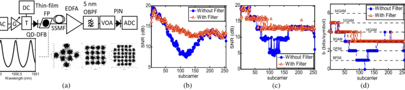
The experimental setup for OFDM transmission is shown in Fig. 1(a). The signal is composed of 255 data subcarriers. Hermitian symmetry is adopted at the inputs of the inverse fast Fourier transform (IFFT) block to allow the generation of a 10 GHz real-valued, baseband signal that is sampled at 24 GSa/s by a digital-to-analog converter (DAC) with 10-bit resolution. 16 samples per symbol are used as a cyclic prefix. The power of the signal that directly modulates a 12 GHz 3-dB bandwidth quantum-dash distributed feedback laser (QD-DFB) [2] is adjusted with an electrical amplifier and an electrical attenuator depending on the fiber length in order to avoid in-band distortions. The QD-DFB is biased at 105 mA and the modulated signal propagates through 25 km to 75 km SSMF. An erbium-doped fiber amplifier (EDFA) is used as a pre-amplifier prior to detection by a 40 GHz PIN photodiode. An analog-to-digital converter (ADC) with 8 bit resolution digitizes the received signal at 40 GSa/s. The power at the input of the photodiode is kept at 0 dBm with a variable optical attenuator (VOA) and demodulation is performed offline. In order to perform the optimization of modulation formats and power levels of the subcarriers, a probing signal is used in which all subcarriers have the same power and are all QPSK modulated. This signal is used to estimate the SNR of the channel (Fig. 1(b)) from error-vector magnitude (EVM) measurements on each subcarrier. The rate-adaptive version of the Levin-Campello algorithm (LCA) is then used to maximize the signal throughput subjected to a mean target bit-error-ratio (BER) of 2.3⨯10-3 over all subcarriers.
M3J.5.pdf OFC 2015 © OSA 2015 DAC G T DC EDFA
~~~
VOA ADC Thin-film FP SSMF 1550 1550.5 1551 -15 -10 -5 0 A m p. R es p. (d B ) Wavelength (nm) PIN 5 nm OBPF QD-DFB 50 100 150 200 250 5 10 15 20 S N R ( dB ) subcarrier Without Filter With Filter 50 100 150 200 250 0 5 10 15 20 S N R ( dB ) subcarrier Without Filter With Filter 50 100 150 200 250 0 2 4 6 b (b its /s ym bo l) subcarrier Without Filter With Filter BPSK 32QAM 64QAM 16QAM 8QAM QPSK (a) (b) (c) (d)Fig. 1: (a) Experimental setup. OFDM subcarriers SNR before (b) and after LCA (c). (d) Subcarriers bit per symbol after LCA.
This is done by means of adaptation of the power coefficient and modulation levels (from BPSK to 32QAM) of the subcarriers. Examples of the received constellations are shown in the insets of Fig. 1(a). The OFDM performance parameters (SNR, EVM, BER) are calculated from 400 symbols.
The thin-film FP filter is placed right after the QD-DFB and the detuning is optimized for each transmission distance by changing the laser operation temperature until the bit-rate is maximized. A variation of ~3.8oC is needed
to cover the FP free-spectral range of 50.5 GHz. The FP amplitude response has a full width at half-maximum of 8.5 GHz and an excursion of 11.9 dB with maximum slope of 1.0 dB/GHz, as shown in the experimental measurement in the inset of Fig. 1(a).
Fig. 1(b) and (c) show the SNRs of the subcarriers after 50 km transmission with and without the FP filter before and after applying the LCA, respectively. As far as transmission without optical filter is concerned, it is noticed from Fig. 1(b) a channel fading dip at ~4.3 GHz (subcarrier 110), which will be studied in-depth in the next section. It can be seen from Fig. 1(c) and (d) that the effect of the algorithm consists in allocating more bits per symbol at the frequencies with the best SNR so that a staircase SNR profile is obtained, hence increasing the bit-rate (from 19.32 Gbit/s to 26.3 Gbit/s before and after LCA, respectively, without the FP). Thanks to the introduction of the FP filter with an optimal laser detuning of ~0.04 nm (with respect to a maximum of the filter transfer function), a significant improvement of the subcarriers SNR (probing OFDM signal, Fig. 1(b)) can be obtained. Such a significant reduction of the depth of the channel fading dip allows increasing the bit-rate after LCA to 32.8 Gbit/s. The same effect is also obtained after propagation over 25 km and 75 km SSMF to provide respectively 36.7 Gbit/s and 28.2 Gbit/s bit-rates (detailed results not shown here), as depicted in Fig. 2(a). The filter allows an increase of the spectral efficiency by 25% at 50 km and provides ~3 bits/s/Hz after 75 km.
In the next section, we investigate more closely the intricate relations between CD, laser chirp and the filter response and their effect on the transmission channel by means of small-signal frequency-domain analyses.
2. Small-signal Frequency-domain Analysis
The small-signal frequency-domain analysis is an established technique to evaluate the chirp and dispersion parameters of lasers and fibers [4,6,7]. Even if the small-signal modulation regime is not always representative of large-signal operation of the channel, SSFDA is of a powerful tool allowing a practical frequency-domain analysis of how the many parameters limiting the capacity of the link will interact with each other.
CD will cause each spectral component of the modulated optical signal to accumulate a different phase at the end of the fiber span. Since the intensity-modulated (IM) signal is double-sideband, destructive beating may occur at some frequencies upon direct-detection depending on the cumulated CD of the link. This results in a frequency-selective channel that will limit the maximum signal bandwidth (bit-rate) that can be transmitted without distortion. The frequencies of the fading dips will move towards lower frequencies when the cumulated CD increases.
Laser chirp, in turn, creates an angle modulation term that will interact with the useful IM. This term is composed of two contributions, the first being proportional to the IM term and the second to its time-integral [6]. Due to the nature of these parasitic terms, they can be considered as a phase modulation (PM) term and a pure frequency modulation (FM) contribution, respectively.
The PM term, which is related to the transient chirp, is proportional to the linewidth enhancement factor α and has the same nature as CD-induced chirp. A positive α in the anomalous dispersion regime will shift the fading dips of the channel response after detection to lower frequencies compared to an unchirped laser submitted to the same amount of dispersion. This will limit even further the maximum allowed bit-rate of the link. This term will also act on the heights of the transmission lobes of the channel due to phase-to-intensity modulation coupling [6,7]. The FM term, which is related to the adiabatic chirp, can nevertheless be beneficial to transmission. This is because this term breaks the symmetry between the sidebands in the modulated spectrum, resulting in imperfect cancellation of the beat terms between the carrier and the symmetric frequency components in the sidebands upon detection. The adiabatic chirp will thus reduce the depths of the channel fading dips. This term is proportional to both α and the
M3J.5.pdf OFC 2015 © OSA 2015 0 5 10 15 -30 -20 -10 0 10 Frequency (GHz) |S 21 | 80 mA without filter 105 mA without filter 105 mA with filter EQ = 1.2 fcEQ = 6.6 GHz = 2.5 fc = 2.2 GHz = 2.5 fc = 1.2 GHz 1540.08-80 1540.20 1540.32 -60 -40 -20 Po we r ( dB m ) 1540.12-80 1540.24 1540.36 -60 -40 -20 Wavelength (nm) Po we r ( dB m ) (a) (b) (c)
Fig. 2. (a) OFDM bit-rates at different fiber lengths. (b) Small-signal frequency responses after propagation through 50 km SSMF. (c) OFDM spectra without (top) and with (bottom) the FP filter
adiabatic chirp coefficient κ and is weaker at higher modulation frequencies. Due to the frequency-dependence of this term, the corner frequency parameter fcis usually adopted to evaluate the impact of the FM term on the channel frequency response [6]. fcindicates a frequency from which the transient chirp effects become dominant over those of the adiabatic chirp.
Fig. 2(b) shows the modulus of the small-signal frequency responses (S21) after 50 km SSMF when the QD-DFB
is biased at 80 mA and 105 mA. While the positions of the channel fading dips (4 GHz, 13 GHz and 17.6 GHz) are defined by both the amount of chromatic dispersion in the link (~825 ps/nm) and the laser α parameter, the maxima of the transmission lobes (10.4 dB) are exclusively determined by α. In addition, we can see in Fig. 2(b) that the depth of the first fading dip decreases from -10.4 to -5.6 dB when the bias current is increased from 80 to 105 mA.
The effects of the FP filter on the channel frequency response after propagation are also shown in Fig. 2(b). A flatter small-signal frequency response is retrieved when the optimal laser detuning obtained in the OFDM transmissions is used. The small-signal responses with and without filter are in very good agreement with the OFDM subcarrier SNR measurements reported in the previous section.
In order to quantify the filter impact on transmissions, we use the method proposed in [7] to extract the laser chirp parameters from the small-signal channel measurements. The theoretical curves after fitting (dashed lines in Fig. 2(b)) show an excellent agreement with the experimental measurements. The resulting values of accumulated dispersion without filter (817.5 ps/nm and 818.5 ps/nm for 80 mA and 105 mA bias, respectively) are in good agreement with the expected dispersion of an SSMF near 1540 nm. An increase of the adiabatic chirp coefficient of the laser when increasing its bias from 80 mA to 105 mA (1.2 GHz to 2.2 GHz) can be inferred from the reduction of the fading dip depth. The laser α parameter is approximately the same (α = 2.9) for both bias currents. Fig. 2(b) also shows that the composite transmitter (laser + filter) could be thought of as an equivalent laser with a smaller α parameter (αEQ = 1.2) and a higher corner frequency (fc,EQ= 6.6 GHz). The overall filter-induced dispersion is estimated to ~ -73.8 ps/nm at this detuning, which accounts for a reduction of 9% of the cumulated CD of the link.
To allow a better understanding of the channel flattening obtained with the FP filter, we compare in Fig. 2(c) the OFDM signal spectra with and without filter with a resolution of 0.04 pm. These spectra show an asymmetry of about 7.5 dB between the two sidebands, demonstrating thus that amplitude filtering will have a vestigial-side-band (VSB) effect on the modulated signal. Such effect allows reducing destructive interferences upon direct-detection thus affecting the channel frequency response after detection [4], similarly to the way the adiabatic chirp does. More precisely, both effects add-up to allow a better side-band attenuation leading thus to a stronger VSB effect.
4. Conclusions
By using both OFDM performance indicators and small-signal analysis, we have shown that the interplay between laser chirp, side-band filtering and filter-induced dispersion can lead to an equivalent transmitter with a smaller α parameter and higher adiabatic chirp coefficient. This equivalent transmitter leads to a flatter DIMDD frequency response that allows up to 25% increase of the OFDM bit-rate at 50 km SSMF and beyond 25 Gbit/s transmission over up to 75 km SSMF.
5. Acknowledgements
This work has been performed under the framework of French ANR project DIQDOT (ANR-11-INFR-0003).
5. References
[1] B. Wedding at al., J. Lightwave Technol. vol.12, no.10, pp.1720-1727, 1994. [2] S. Joshi et al., Electron. Lett., vol.50, no.7, pp.534-536, 2014.
[3] L.-S. Yan et al., Opt. Express, vol. 13, no.12, pp. 5106-5115, 2005. [4] M. McAdams et al., Appl. Phys. Lett., vol.71, no.7, pp. 879-881, 1997. [5] J. L. Wei et al., J. Lightwave Technol., vol. 29, no. 18, pp. 2861-2870, 2011. [6] L. Bjerkan et al., J. Lightwave Technol., vol. 14, no. 5, pp. 839-850, 1996. [7] L. Anet-Neto et al., J. Lightwave Technol., vol.31, no.2, pp.334-342, 2013.