HAL Id: hal-01475834
https://hal.archives-ouvertes.fr/hal-01475834
Submitted on 24 Feb 2017HAL is a multi-disciplinary open access archive for the deposit and dissemination of sci-entific research documents, whether they are pub-lished or not. The documents may come from teaching and research institutions in France or abroad, or from public or private research centers.
L’archive ouverte pluridisciplinaire HAL, est destinée au dépôt et à la diffusion de documents scientifiques de niveau recherche, publiés ou non, émanant des établissements d’enseignement et de recherche français ou étrangers, des laboratoires publics ou privés.
Effect of M-EMS on in-mould transient flow during
continuous casting
Luca Marioni, Jose Rodolfo Alves Zapata, François Bay, Elie Hachem
To cite this version:
Luca Marioni, Jose Rodolfo Alves Zapata, François Bay, Elie Hachem. Effect of M-EMS on in-mould transient flow during continuous casting. International Journal of Applied Electromagnetics and Mechanics, IOS Press 2016, 53 (S1), pp.S3-S10. �10.3233/JAE-162245�. �hal-01475834�
EFFECT OF M-EMS ON IN-MOULD TRANSIENT FLOW DURING CONTINUOUS CASTING
L. Marioni (1,2,†), J. Alves Z. (1), F. Bay (2) and E. Hachem (2)
(1)
Transvalor S.A.,
Parc de Haute Technologie - Sophia Antipolis 06255 MOUGINS cedex, France
(2)
MINES ParisTech, Center for Materials Forming (CEMEF), UMR CNRS 7635, BP 207, 06904 Sophia Antipolis, France
(†)
Corresponding author. Email: [email protected]
Keywords: continuous casting, electromagnetic stirring, mesh adaptation, finite elements
This is the author’s copy of the accepted manuscript. Please refer to:
≪L. Marioni, J. Alves, F. Bay, E. Hachem. Effect of M-EMS on in-mould transient flow during continuous
casting. International Conference on Heating by electromagnetic Sources. Pages 3-10. Padua (Italy), 2016.≫
For the edited conference proceeding and to:
≪L. Marioni, J. Alves, F. Bay, E. Hachem. Effect of M-EMS on in-mould transient flow during continuous
casting. International Journal of Applied Electromagnetics and Mechanics, 2016. doi: 10.3233/JAE-162245 ≫
for the related published article.
ABSTRACT. Electromagnetic stirring (EMS) is widely used to increase the efficiency in
continuous casting process of steel. In particular, in-mould applications (M-EMS) allow decreasing the free surface fluctuation, controlling the velocity field and decreasing the turbulence of the flow. Since laboratory-scale tests are not fully representative of the process and industrial measurements are both expensive and difficult to carry out, numerical simulation is a strong tool to study and optimize these electromagnetic applications in steel industry. These simulations cannot fully model the process of its multiphysical nature and the simulation of all the phenomena involved would lead to huge computational costs, which is one of the main limits in the current situation. For this reason, this work aims at starting searching a coupling algorithm which could guarantee both computational efficiency and accuracy of the final results.
INTRODUCTION
In continuous casting processes the liquid metal is injected into the mould. The final steel shell is obtained after the solidification which starts in the mould and continues in the strands. Electromagnetic devices such as stirrers and brakers are well known technologies used to improve both the quality of the final product and the casting speed. The main defects of the final shell in terms of micro-structure and surface cracking can be directly related to in-mould phenomena: temperature variation, velocity and pressure of liquid steel, free-surface behaviour and slag entrainment are some of the main causes of defects in the final product. With the purpose of controlling the process and preventing the final product from defects, the process has been enhanced with electromagnetic devices such as stirrers (EMS) and brakers (EMB). The main difference is that the stirrers work under the supply of AC current and
produce dynamics magnetic fields. Brakers are permanent magnets or circuits fed by DC current, thus they produce constant magnetic fields. Despite the differences they are based on the same idea that the superposition of a magnetic field to the metal flow will generate Lorentz forces which can drive the flow in accordance with the process' design. The physical phenomena occurring in the mould is a multiphysics problem which includes liquid flow, multiphase analyses, electromagnetic computation, heat transfer and solidification processes where each of these physics depends on the others. Numerical simulations are one of the main tools used to design the process because it is too complex to be solved analytically[1]. Also, experimental data are very expensive and difficult to obtain because of the high temperature of the casting process. The main drawback of these simulations is the high computational effort required to simulate the highly multiphysical phenomena including electromagnetic field, multiphase fluid flow, heat transfer and solidification. The study of an efficient coupling is therefore essential to neglect non-relevant aspects of the modelling and obtain fast and reliable simulation algorithms which can be exploited in the industrial world.
SIMULATION TEST CASE
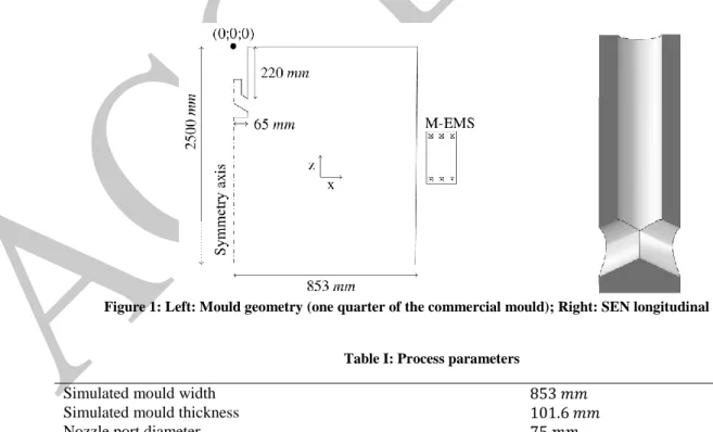
The main purpose of the current work is to create an efficient coupling strategy able to simulate electromagnetic stirring in continuous casting processes. For this reason, a simplified test case has been used. The studied case is a slab casting process and the mould’s geometry has been taken from literature (Singh's work [2]), but only a quarter of it has been included in the simulation (see figure 1). A simplified electromagnetic stirrer has been positioned
away from the mould in the direction of the narrow face and between and under the free surface level. The EMS device is a solenoid fed by a pulsating AC current and produces a horizontal pulsating magnetic field directed from the narrow face in the direction of the nozzle plan. The geometry of the device is simplified since available data on commercial stirrers were not accurate enough to perform a simulation. In the current work we content to simulate a realistic Lorentz force field, since the aim is to study the interaction of the stirrer on the flow more than to obtain specific industrial results. The main data used in the simulation are reported in table I.
Figure 1: Left: Mould geometry (one quarter of the commercial mould); Right: SEN longitudinal section.
Table I: Process parameters
Simulated mould width
Simulated mould thickness
Nozzle port diameter
Nozzle bore diameter (inner)
Nozzle port angle
SEN submergence depth
Casting speed
Bulk velocity in SEN cross section
Thickness of the solidified shell √ mm 0.57
Kinematic viscosity of molten steel
Density of molten steel
Resistivity of molten steel Resistivity of solids parts Inlet Reynolds number
Inlet magnetic Reynolds number Eddy magnetic Reynolds number
0.13 0.15 Intensity of current Frequency MATHEMATICAL MODEL Governing equations
The potential model has been used to model the electromagnetic field (EMF). Thus, the evolution in time of the EMF is describes by the following system:
{ ( )
( ) (1)
where and are the free space and material's relative magnetic permeability respectively. is the magnetic vector potential, is the scalar electric potential, is the medium velocity, and is the electrical conductivity. Boundary conditions have been set on the external surface of the inductor by imposing the RMS value of the current density; boundary conditions on the magnetic vector potential have been set as follow:
{ (2)
where is the outward versor normal to the boundary surface. The second equation in system (2) constraints the vector to be tangent to the boundary surface so that all the computed
magnetic lines lie totally inside the domain. The convective term can be neglected because the Reynolds magnetic number is , which leads to . For further justification to these assumptions, we refer to [3]. These conditions ensure that the EMF is not affected by the fluid motion in EMS applications. The term is automatically
respected when Nedelec finite elements [6] are used, so the system (1) can be de-coupled; hence the electric potential is computed from the second equation and added into the first one as a source term. The consequent weak formulation of the problem is:
, (3)
where are the shape functions for Nedelec elements. Since the flow is supposed to be over the Curie point and the system reacts linearly with respect to the source term, an harmonic resolution of the time evolution has been adopted. The consequent complex system has been solved via the real-equivalent formulation proposed in [7]
(4)
where the convective term due to fluid motion has been neglected for the aforementioned reasons. Both the time evolving and time averaged Lorentz forces have been considered in two different simulations because the literature does not provide a unique criterion to accept the usage of the averaged field. Such criterion should be dependent on frequency [3], on the skin depth phenomenon and on the Stuart number [4]. The turbulent fluid flow has been modelled by the incompressible Navier-Stokes equation. The Lorentz forces have been considered as a source term. No buoyancy effect was considered, since it is negligible in comparison to inertia and electromagnetic influences. A variational multiscale (VMS) approach [8] has been used to solve Navier-Stokes equations. This method allows to
implicitly consider the effect of small scale turbulence on the larger eddies developed in the flow. Both velocity and pressure fields have been enriched and stabilized according to [9]:
{
∑ ∑
∑
(5)
with and the momentum and continuity residuals from the modelling of the fine scale, respectively. and are the density and the viscosity of molten metal, is the pressure and is the volumetric force, whereas and are the shape functions of the weak
formulation. System (3) considers the fine scale modelling without explicitly tracking it. The stabilizing terms and (whose theoretical derivation is detailed in [9]) enable the model to overcome the instability of the classical formulation arising in convection dominated flows and to deal with the spurious pressure oscillations. No-slip boundary conditions have been imposed at the liquid steel-mould interface and at the free-surface to model the effect of slag friction. Dirichlet boundary conditions on velocity have been imposed at the inlet and outlet surfaces of the mould in respect to the mass conservation.
The coupled system has been simulated through the so called two meshes two solvers
approach [5, 10, 11]. The electromagnetic problem has been solved with Matelec over a
domain which included the air and the simplified stirrer. The Lorentz forces have thus been imported in Thercast ® which solves the mechanical problem over the fluid domain. This approach allows us to exploit specific solvers and optimized meshes for each involved physic.
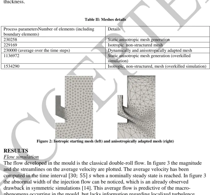
Anisotropic mesh adaptation
In [12] a posteriori error estimate based on the length distribution tensor approach and the associated edge based error analysis is proposed. This error estimation algorithm is the base for the anisotropic meshing scheme adopted in the current work developed in [13] in the case of Navier-Stokes, multi-field re-meshing.
The mesh in the fluid domain is computed as output of an error optimization analysis performed along the edges and referred to user defined fields; we propose the mesh to be adapted according to the following multi-field vector:
( ) { (| |) (| |)} (6)
where is the velocity field, is the distance from the boundary, is the volumetric force and are the nodal indexes.
Implicit-Static adaptation: the mesh is anistropically adapted to the boundaries and in the weak regions. The obtained mesh is then used as a fixed mesh during the whole computation.
Explicit-Dynamic adaptation: the mesh is dynamically adapted during the
computation according to the multicriteria vector (eq. (4)) computed from the solution. In figure 2 we can see how the mesh is anisotropically adapted to the flow in the nozzle area. A resume of the meshes used in the simulations is proposed in table II; two overkilled
simulations obtained by using different meshing techniques have been performed to check the convergence of results. All the results in the following are taken from the static anisotropic adapted simulation, which is in good agreement with the dynamic re-meshing and the overkilled simulations. The coarse isotropic mesh shows instead sensible discrepancies with the overkilled simulation, because it is not fine enough in the nozzle and in the narrow face thickness.
Table II: Meshes details Process parametersNumber of elements (including
boundary elements)
Details
230258 Static anisotropic mesh generation
229169 Isotropic non-structured mesh
230000 (average over the time steps) Dynamically and anisotropically adapted mesh 1136972 Static anisotropic mesh generation (overkilled
simulation)
1534290 Isotropic, non-structured, mesh (overkilled simulation)
Figure 2: Isotropic starting mesh (left) and anisotropically adapted mesh (right) RESULTS
Flow simulation
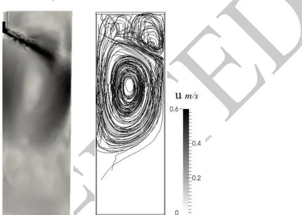
The flow developed in the mould is the classical double-roll flow. In figure 3 the magnitude and the streamlines on the average velocity are plotted. The average velocity has been
computed in the time interval when a nominally steady state is reached. In figure 3 the abnormal width of the injection flow can be noticed, which is an already observed
drawback in symmetric simulations [14]. This average flow is predictive of the macro-phenomena occurring in the mould, but lacks information regarding localized turbulence, which has a strong impact on metallurgical properties. The turbulence leads to short-time sub-flows detected by the non-average solution; this difference can be measured in term of
√∑ ̅
(7)
where is the instantaneous velocity, ̅ is the average velocity, is the number of time-steps and represents the i-th time step.
Figure 3: Averaged velocity magnitude (left) and streamlines in the double-roll area (right)
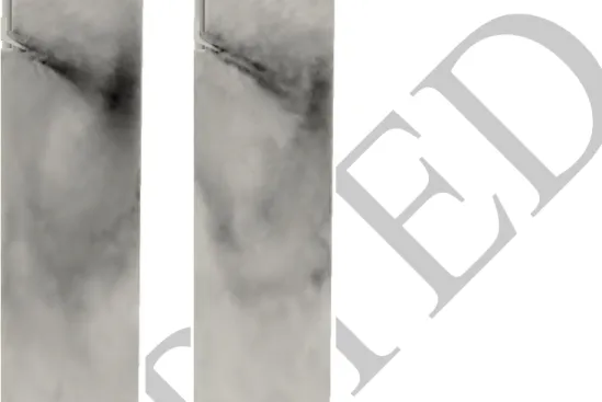
In figure 4 the normalized velocity pulsations during the nominal steady state regime is plotted. We see that a large deviation is present in the main flow region and the maximum deviation occurs where the injected flow impacts on the narrow face; the flow in this region is highly turbulent and this turbulence has effect on the mushy zone. When the stirrer is turned on (figure 4 right) the velocity pulsations is decreased in the meniscus zone, which implies the flow to be closer to the steady state. Despite the low level of the magnetic field in the inner zone of the mould, EMS affects the injection flow as well. The flow is smoother and easily turns in the double-roll pattern, while in the non-stirred simulation the unstable flow close to the narrow face led to dynamic effects in the main injection flow. A second effect of the stirrer is to decrease the global velocity of the flow, which is important especially from a simulation point of view. In figure 5 left, the velocity profile along a vertical line 5 cm far from the central axis is plotted. We see that the horizontal velocity related to the main eddy ( is high, especially when compared to the vertical velocity. This means that the simulated flow and its symmetric one (in the second half of the mould) would have a strong impact in this area, which would create turbulence and lead the global flow to be
non-symmetric. For this reason, the flow with no EMS should be simulated without any symmetry condition. On the contrary, we see that the horizontal velocity in the flow with EMS is lower as well as its ratio with the vertical velocity. This result implies that in the stirred case, the geometrical symmetry plane is more likely to behave like a mechanical symmetry plane. The main effects of the stirrer can be detected close to the narrow face, along the symmetry plane
and on the injection flow, but not in nozzle area. In figure 5 right the velocity across the exit central line of the nozzle is plotted and no sensible differences between the stirred and non-stirred solution are predicted.
Figure 4: Velocity pulsations with no EMS (left) and with EMS (right)
Figure 5: Velocity profile at 5cm from central axis (left) and velocity magnitude at the nozzle exit port (right)
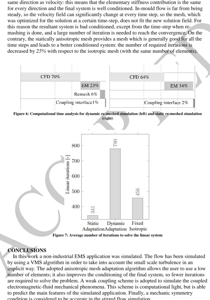
The computational effort of the simulation is not highly affected by the weak coupling between the EM and CFD simulations: in figure 6 an analysis of the computing time is presented. The dynamic mesh adaptation is computationally expensive even if the re-meshing has been performed every 14 time steps. As we can see in figure 7, this choice is not good in terms of optimization. The anisotropic adaptation makes the elements to be stretched in the
same direction as velocity: this means that the elementary stiffness contribution is the same for every direction and the final system is well conditioned. In-mould flow is far from being steady, so the velocity field can significantly change at every time step, so the mesh, which was optimized for the solution at a certain time-step, does not fit the new solution field. For this reason the resultant system is bad conditioned, except from the time-step when re-mashing is done, and a large number of iteration is needed to reach the convergence. On the contrary, the statically anisotropic mesh provides a mesh which is generally good for all the time steps and leads to a better conditioned system: the number of required iterations is decreased by 25% with respect to the isotropic mesh (with the same number of elements).
Figure 6: Computational time analysis for dynamic re-meshed simulation (left) and static re-meshed simulation (right)
Figure 7: Average number of iterations to solve the linear system
CONCLUSIONS
In this work a non-industrial EMS application was simulated. The flow has been simulated by using a VMS algorithm in order to take into account the small scale turbulence in an implicit way. The adopted anisotropic mesh adaptation algorithm allows the user to use a low number of elements; it also improves the conditioning of the final system, so fewer iterations are required to solve the problem. A weak coupling scheme is adopted to simulate the coupled electromagnetic-fluid mechanical phenomena. This scheme is computational light, but is able to predict the main features of the simulated application. Finally, a mechanic symmetry condition is considered to be accurate in the stirred flow simulation.
ACKNOWLEDGEMENTS
The authors give thanks to Transvalor S.A. for funding this research and for the continuous support which allowed the complete exploitation of its software.
REFERENCES
[1] Fujisaki, K. (2002). 3-D MHD calculation in consideration of free surface, heat transfer and solidification. International Journal of Applied Electromagnetics and Mechanics,
14,9-14.
[2] Singh, R., Thomas, B.G and Vanka, S.P. (2014). Large eddy simulations of double-ruler electromagnetic field effect on transient flow during continuous casting. Metallurgical and
materials transactions B, 45B,1098-1114.
[3] Mureau, R. (1990). Magnetohydrodynamics, volume 3, Springer science.
[4] Felten, F., Fautrelle, Y., Du Terrail, Y. and Metais, O. (2004). Numerical modelling of electromagnetically-driven turbulent flows using LES methods. Applied Mathemattical
Modelling., 28, 15-27.
[5] Barna, M., Javurek, M., Reite, J. and Lechner, M. (2009). Numerical Simulations of Mould Electromagnetic Stirring for Round
Bloom Strands. BHM Berg-und Huttenmannische Monatshefte, 154, 518-522.
[6] Nedelec, J. C. (1980). Mixed finite elements in . Numerische Mathematk., 35(3), 315-341.
[7] Marioni, L., Alves, J., Hachem, E. and Bay, F. (2017) . A new approach to solve complex valued systems arising from the solution of Maxwell equations in the frequency domain through real-equivalent formulations. Numerical Linear Algebra with Applications, 24:e2079.
[8] Hughes, T.J.R., Feijóo1, G.R., Mazzei, L. and Quincy, J.B. (1998). The variational multiscale method - a paradigm for computational mechanics. Computer Methods in
Applied Mechanics and Engineering,166(1:2),3-24.
[9] Hachem, E., Rivaux, B., Kloczko, T., Digonnet, H. and Coupez, T. (2010). Stabilized finite element method for incompressible flows with high Reynolds number. Journal of
Computational Physic., 229(23), 8643-8665.
[10] Fujisaki, K. (2001). In-Mold Electromagnetic Stirring in Continuous Casting. IEEE
Transactions on Industry Applications,8, 2591-2598.
[11] Thomas, B. G. and Chaudhary, R. (2009). State of the Art in Electromagnetic Flow Control in Continuous Casting of Steel Slabs: Modeling and Plant Validation in 6th
International Conference on Electromagnetic Processing of Materials EPM.
[12] Coupez, T. (2011). Metric construction by length distribution tensor and edge based error for anisotropic adaptive meshing. Journal of computational physics,230, 2391-2405. [13] Coupez, T. and Hachem, E. (2013). Solution of high-Reynolds incompressible flow with
stabilized finite element and adaptive anisotropic meshing. Computer Methods in Applied
Mechanics and Engineering, 267,65-85.
[14]Yuan, Q., Zhao, B., Vanka, P. and Thomas, B. G. (2005). Study of computational issues in simulation of transient flow ini continuous casting. Steel Research International, Special