HAL Id: hal-01259655
https://hal.archives-ouvertes.fr/hal-01259655
Submitted on 22 Jan 2016HAL is a multi-disciplinary open access archive for the deposit and dissemination of sci-entific research documents, whether they are pub-lished or not. The documents may come from teaching and research institutions in France or abroad, or from public or private research centers.
L’archive ouverte pluridisciplinaire HAL, est destinée au dépôt et à la diffusion de documents scientifiques de niveau recherche, publiés ou non, émanant des établissements d’enseignement et de recherche français ou étrangers, des laboratoires publics ou privés.
Onboard Real-time System for Digitizing and
Geo-referencing of 3D Urban Environments
Iyad Abuhadrous, Fawzi Nashashibi, Claude Laurgeau, Francois Goulette
To cite this version:
Iyad Abuhadrous, Fawzi Nashashibi, Claude Laurgeau, Francois Goulette. Onboard Real-time System for Digitizing and Geo-referencing of 3D Urban Environments. International Conference on Advanced Robotics (ICAR), Jun 2003, Coimbra, Portugal. �hal-01259655�
Onboard Real-time System for Digitizing and
Georeferencing of 3D Urban Environments
I. ABUHADROUS, F. NASHASHIBI, C. LAURGEAU, F. GOULETTE
Center of robotics
Ecole des Mines de Paris
75272 PARIS Cedex 06, FRANCE
ABSTRACT
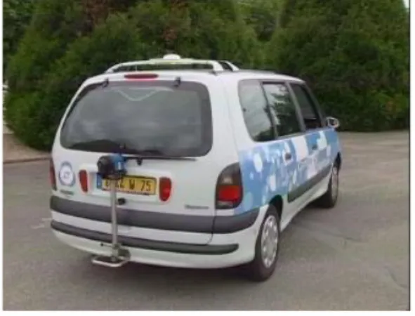
The onboard real-time system for three-dimensional environment reconstruction consists of an instrumented vehicle equipped with a 2D laser range scanner for data mapping, and GPS, INS and odometers for vehicle positioning and attitude information. The advantage of this system is its ability to perform data acquisition during the robot or vehicle navigation; the sensor needed being a basic 2D scanner with opposition to traditional expensive 3D sensors. Real-time data fusion is performed using an onboard software platform called RTMAPS. This system integrates the laser raw range data with the vehicle’s internal state estimator and is capable of reconstructing the 3D geometry of the environment by real-time geo-referencing instead of traditional pose estimation and data fusion approaches.
Key words: laser-range scanner, urban 3D model,
geo-referencing, real time reconstruction, Visualization,
RT
MAPs.
Introduction
The goal of this work is to develop a system able to generate and reconstruct 3D models for urban environments (especially roads) in real time. The data obtained by this system could be good resources for developing urban 3-D databases, which have numerous military and civil applications such as navigation, training and simulation, virtual reality planning, video and computer games, etc.
In general, there are two kinds of techniques for measuring three-dimensional geometrical data. One is based on intensity image. Another is based on range data. Several researches using photographs or CCD/video cameras have demonstrated that 3D information can be extracted using motion [4] and stereoscopic techniques [8]. The difficulties in reliable stereo matching, distortion from limited resolution and unstable geometry of CCD
cameras are the major obstacles to reconstruct a 3D model of complicated environment with necessary accuracy and robustness. On the other hand, reconstructing 3D objects using range sensors has concentrated on reconstructing small objects such as teeth, bust, mechanical parts, etc. [1,2,3,8]. With the development of eye-safe laser range scanner, reconstructing relatively large objects in urban environment using range data becomes technically feasible. Range images acquired by range sensor succeed in solving the difficulties in calculating 3D coordinate that optical images encountered.
According to mounting platform, laser scanning technology is divided into airborne laser scanning [5,8] and ground-based laser scanning [3, ]. Ground based laser scanning is mainly applied to rebuild 3D city models and to collect local geographic information, The vehicles can give highly dense and more accurate maps, but only for the limited areas they can access.
Highly accurate positioning (localization) is one of the major issues that have to be discussed when mounting laser range scanner on a mobile platform. Many research efforts have been contributed on this topic [1, 2, 3], and a number of systems based on the integration of GPS (Global Positioning System), INS (Inertial Navigation System). In these systems, the INS system, which outputs velocity and attitude, is implemented to update positioning data when GPS signal is not available, a common problem if the outage of GPS data is long, to solve it, the odometers data has been integrated with the INS system output. In [1] a laser scanner is used to help the GPS/INS in localization.
In our approach the laser is redirected to scan out a plane perpendicular to the forward driving direction [3], and GPS/INS/Odometers for vehicle localisation. With this configuration, the combination of the scanner’s head rotation and the vehicle’s forward motion provides coverage of roads and buildings (surrounding area). The localisation accuracy is less than 0.15 meter, the vehicle
has been driven at speed 10-40 km/h. This means that the distance between two profiles is about 0.25 to 1 meter. The whole application was integrated in the vehicle using our RTMAPS real-time platform.
Figure 1: The instrumented vehicle and laser scanner
System Configuration
Figure 2 shows a block diagram with the main components of the system. The IBEO Laser scanner “LD A AF” is used for the scanning, it can return the range for targets up to 200 meters for reflecting targets and up to 40m for dark targets with 1-to-5 cm accuracy. The scanning angle is 270, and the angular resolution is 0.25 at a 10Hz scan frequency, this means that we have 10800 samples per second. In this scanner, the distance to the target is calculated from the time of flight between the transmission and the reception of the light pulse.
For vehicle localisation, the state estimator is a processing module which combines data from GPS, IMU and odometers using Kalman filter. The outputs of the state estimator are the position and velocity of the vehicle at 84Hz. A Trimble DGPS receiver is used, offers absolute positioning in a world-fixed reference frame at 10 Hz. With an accuracy of 5m. Data latency ranges between 30msec and 150msec.
The Inertial Measurement Unit of crossbow comprises of three accelerometers, three gyros, and sends 85 measurements per second. The wheel encoders provide forward speed with an accuracy of 1 m/s at 10 Hz. The encoders are mounted on the two back wheels. The resolution of one encoder is 32 pulses per revolution. The data logger PC has a mother board with two 750MHz processors Pentium II, used to performs real-time calculation and filtering of acquired data.
Figure 2: Block diagram of the main components of the
system.
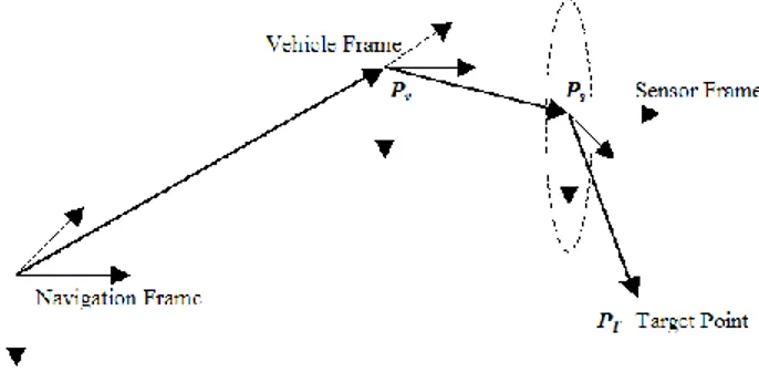
The Measurement Process
The goal of the measurement process is to convert laser measurements of a target point PT into 3D coordinates in an Earth fixed reference frame or Mapping Coordinate Frame, Nav
T
P . The following steps describe the kinematics calculations required for coordinates transformation (refer to Figure 3):
1) The first step is to calculate the coordinates of the target point in the laser scanner sensor frame. The plane in which the laser scans, defines the Y-Z plane of the sensor frame. The scan angle, s, and the distance to the target r are returned by the laser scanner, and the s
coordinates can be calculated by:
s s s s Scanner Tr
r
z
y
P
cos
sin
0
0
2) A rigid transform (translation and rotation) is required to locate the laser scanner (sensor frame) in the vehicle frame. The transnational and rotational offsets v
s P , and Veh
Scanner
are constant and were determined through a hand-eye typical calibration. If there is no rotation between the sensor frame and the vehicle frame, this means Veh
Scanner
is a unity matrix. And if we assume that the origin of the vehicle frame and the sensor frame are the same, then Veh
s
P will be zero vector.
3) The state estimator using Kalman filter is used to integrate the GPS/INS/Odometers and provides the position Nav
v
P and attitude of the vehicle. The origin of the vehicle frame is located between the two rear wheels axial, and the NED (North, East, Down) is the used
navigation coordinates system. The attitude data is used to calculate Nav
Veh
, a 3x3 rotation matrix used to transform points from the vehicle frame to the navigation frame.
Figure 3: The geometry of the measurement
process.(Geo-referencing)
4) Using these definitions, the coordinates of the target in the navigation frame can be computed by:
Nav s Scanner T Nav Scanner Nav T
P
P
P
but Veh Scanner Nav Veh Nav Scanner
and Nav v Veh s Nav Veh Nav sP
P
P
Nav v Veh s Nav Veh Scanner T Veh Scanner Nav Veh Nav TP
P
P
P
This configuration provides all the information needed to recover the 3-D structure of scanned surfaces. Unfortunately, errors affect each step of the measurement process and corrupt the final 3-D map. Reducing these errors is critical to achieve highly accurate results.
Errors
The inaccurate estimation of errors are due to the filtered position Nav
v
P , sensor translation Veh s
P , or laser range measurement
r
s, result in an error on target positionNav T
P . On the other hand, a 1 degree angular error in attitude estimation Nav
Veh
, sensor orientation Veh Scanner , or scanning angle s produces an equally large error in the expected direction of the laser beam, resulting in an error of more than one meter at 60 m range. This motivates the attempt to remove as many sources of angular errors as possible.
There are two fundamental sources of angular error in our system: errors due to incorrect scanning geometry, and errors due to the inaccurate model of vehicle motion. The first source is reduced by a careful calibration, and the second is reduced by synchronizing the various data
sources and interpolating between measurements, and by data fusion and estimation using digital filtering.
Data Acquisition and Processing
RTMAPs “Real Time Mines Automotive Prototyping
System” in [11] is a software platform capable of recording data from multiple sensors in real time, in order to build a synchronized data base. This platform allows us to record databases without any loss of data and to replay it on a standard computer in the same conditions than when they have been recorded in our vehicle. We then used the RTMAPS facilities (interfaced with Matlab, Excel, Scilab), to analyze these data and develop new algorithms using multiple programming languages (C/C++, Java, VBasic). When algorithms and applications have been validated in the laboratory, we can immediately put them in the vehicle’s RT
MAPs based data logger, and test them but using specific and real hardware [13]. The use of this accurate dating system has also helped in synchronizing real time data flows from different sensors. While Odometer and INS signals are received with a nearly constant latency (error is far less than 1ms), both GPS positioning calculation time and reception delay are extremely variable. It’s however possible, thanks to the Pulse Per Second GPS signal, to calculate them and introduce these delays in our algorithms.
The GPS, IMU, odometers and Laser scanner range data were logged using RTMAPS. IMU acceleration, angular rate, and roll and pitch angles were recorded at a 84 Hz rate, while GPS position and velocity data was logged at a rate of 10 Hz. Odometers data at 10 Hz.
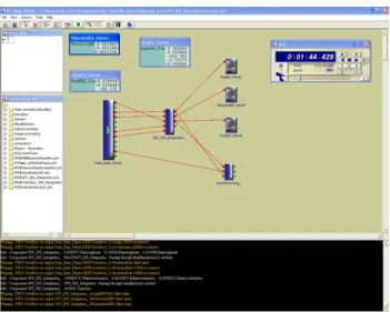
Real-time processing of the data was performed during data collection. However, offline processing was performed in a “playback” mode whereby real-time situations are approximated. All the algorithms have been written in C++, and the user interface of RTMAPs in Java. Figure 4 shows the users interface of RTMAPS, the first component is the database which contains the raw laser range data, position and velocity from GPS, acceleration, and angular velocity from the IMU. And the second component evaluate the IMU data to get the position, velocity and orientation of the vehicle, then integrate them with the GPS solution by Kalman filtering to get the vehicle state. The third component has three inputs: the vehicle position, the range data, and the vehicle orientation (roll, pitch, yaw), it creates automatically output file containing the 3D points with respect to a geographical reference frame (Geo-referencing).
Figure 4: User interface of RTMAPS
Results and Discussion
Figure 5 shows the result of the scanned area using the presented system, it presents the façade of Ecole des Mines de Paris, this image contains approximately 1 million points during 1.5 minutes of trajectory, the distance between two profiles is about 0.25 to 1 meter and the distance between two points in the same profile is depending on the target point range. We can extract the road surface, and another features like trees, bus stop, and vehicles.
The implemented onboard software can register and visualise the 3D model (cloud of points) during navigation. Another sites have been conducted with a longer trajectory can be presented in the Camera-ready full paper.
Figure 5: The Ecole des Mines de Paris range points.
Conclusion and Future Studies
The goal of this research is to develop a system which is capable of acquiring data in three dimensions. To built an accurate 3D model of urban out-door environment time, a vehicle-borne laser range scanner with a GPS/INS/odometer based navigation system. The system operates in real time and builds high resolution maps of static environments around the vehicle.
The next work will be concentrated on a careful study of the system to determine its actual accuracy and to minimise the measurement error. Feature extraction and data segmentation of these laser data (clouds), to classify objects into buildings, trees, roads surfaces, stationary vehicles and other classes. Integrating line camera or CCD for appearance (color) information, by projecting and re-sampling line images on the geometric model, to get a textured CAD model of urban environments. An finally filtering the moving (dynamic) obstacles around the vehicle.
Bibliography:
1. H. Zhao, R. Shibasaki, "Reconstructing Urban 3D Model using Vehicle-borne Laser Range Scanners", Proc. of the third International Conference on 3D Digital Imaging and Modeling, May 2001 Quebec City.
2. Sukkarieh, S. (2000). Low Cost, High Integrity, Aided Inertial Navigation Systems for Autonomous Land Vehicles. Ph.D. Thesis, Australian Centre for Field Robotics, Dept. of Mechanical and Mechatronic Engineering, The University of Sydney, Sydney, Austrlia.
3. H. Zhao, R. Shibasaki, "Reconstructing Textured CAD Model of Urban Environment using Vehicle-borne Laser Range Scanners and Line Cameras", Proc. of International Workshop on Computer Vision Systems, Jul 2001 Vancouver 4. S. Thrun, W. Burgard, and D. Fox. A real-time
algorithm for mobile robot mapping with applications to multi-robot and 3D mapping.ICRA-2000. Best Conference paper award.
5. J.R. Miller, O. Amidi, and M. Delouis, "Arctic Test Flights of the CMU Autonomous Helicopter," Proceedings of the Association for Unmanned Vehicle Systems International 1999, 26th Annual Symposium, July, 1999.
6. El-Hakim S. F. , C. Brenner, G. Roth, A multi-sensor approach to creating accurate virtual environments. ISPRS Journal of Photogrammetry & Remote Sensing, vol. 53 (1998) 379–391.
7. J.R. Miller and O. Amidi, "3-D Site Mapping with the CMU Autonomous Helicopter," Proceedings of the 5th International Conference
on Intelligent Autonomous Systems (IAS-5), June, 1998.
8. Grau, O., "3-D Modelling of Buildings using High-Level Knowledge", Proc. of Computer Graphics International 1998 (CGI'98). June 22nd - 26th, 1998, Hannover, Germany
9. H. Shum, K. Ikeuchi, and R. Reddy, "Virtual reality modeling from a sequence of range images," IEEE / RJS International Conference on Intelligent Robots and Systems, Vol. 1, September, 1994, pp. 703-710.
10. I. Kweon and T. Kanade, "High Resolution Terrain Map from Multiple Sensor Data," Proceedings of IROS '90, IEEE International Workshop on Intelligent Robots and Systems '90, 'Towards a New Frontier of Applications', Vol. 1, July, 1990, pp. 127 - 134.
11. F. Nashashibi, B. Steux, P. Coulombeau, C. Laurgeau, "RTMAPs a framework for prototyping automotive multi-sensor applications". In Proc. Of the IEEE Intelligent Vehicles Symposium 2000. Dearborn, MI, USA, October 3-5, 2000.. 12. http://www.arcos2004.com, Action de Recherche
pour une Conduite Sécurisée
13. http://www.carsense.com, European Research Project for Sensing of Car Environment at Low Speed Driving.