HAL Id: tel-02489996
https://pastel.archives-ouvertes.fr/tel-02489996v2
Submitted on 25 Feb 2020
HAL is a multi-disciplinary open access
archive for the deposit and dissemination of sci-entific research documents, whether they are pub-lished or not. The documents may come from teaching and research institutions in France or abroad, or from public or private research centers.
L’archive ouverte pluridisciplinaire HAL, est destinée au dépôt et à la diffusion de documents scientifiques de niveau recherche, publiés ou non, émanant des établissements d’enseignement et de recherche français ou étrangers, des laboratoires publics ou privés.
matériaux cimentaires
Romain Duballet
To cite this version:
Romain Duballet. Systèmes constructifs en fabrication additive de matériaux cimentaires. Génie civil. Université Paris-Est, 2019. Français. �NNT : 2019PESC1011�. �tel-02489996v2�
Laboratoire Navier
Ecole Nationale des Ponts et Chaussees
CNRS, IFSTTAR
Building systems in robotic extrusion of
cementitious materials
Romain Duballet
Supervisors:
Olivier Baverel, Justin Dirrenberger
Rapporteurs:
Antonella Mastrorilli, Theo Salet
Examiners:
Jean-Francois Caron, Arnaud
Delaplace, John Orr, Arnaud Perrot
Abstract
This work deals with a novel field of investigation for civil engineering and building industry called large scale 3D printing, or additive manufacturing, of cementitious materials. It makes use of robotic devices to progressively bring a fresh concrete or mortar into a desired shape, without using traditional formworks. The main associated ambitions are productivity and sustainability, achieved through automation and geometric complexity.
Many approaches are able to succeed in correctly shaping a cementitious matter in space and ensuring its final characteristics. Among them a recent one can be called robotic extrusion, on which the present work focuses. It consist in pumping and depositing a fresh mortar, or fine concrete, relying on its early age structuration rather than on the shaping abilities of a formwork. If the physical and rheological phenomena at stake begin to be understood, there is no clear knowledge of a specific strategy yet, and many strategies are developed in parallel by the community. The first part of this work presents those, and aims at providing sufficiently distinctive definitions, see chapter 2. Three idealized approaches are proposed, differing in the history of solicitations and structuration for the printed material.
Beyond the rheology oriented approach, this work seeks to broaden the scope of concrete printing and shift the discussion from materials to final building systems. Indeed, not only a construction product often includes more than just concrete, but the printing itself can be generalized to a more complete understanding. This is the ambition of a proposed classification system, presented in chapter 3.
Illustrating the notion of generalized printing, a novel process is proposed in chapters 4 and 5. It makes use of a combination of robotic extrusion and assembly of masonry elements in insulating foam to fabricate space truss structures of improved performances.
Acknowledgements
I would like to thank the whole Navier laboratory to have kindly welcomed me for these three amazing years of conjoint work, particularly my supervisors, Olivier Baverel and Justin Dirren-berger, for their patience, kindness and advice, and also Marie-Françoise Kaspi, Jean-François Caron and Romain Mesnil, thanks to whom all of this was made possible.
I thank also Vivien Esnault and François de Larrard at LafargeHolcim Research and Develop-ment for fruitful discussions. Support from LafargeHolcim is gratefully acknowledged.
Many thanks to Antonella Mastrorilli, Theo Salet, Arnaud Delaplace, John Orr and Arnaud Perrot for accepting to be members of this thesis commitee.
A special thank to my printing colleagues, Nicolas Ducoulombiers, Paul Carneau and Leo Demont, who have shared precious thoughts, hard work and laughs during this creative period.
To Hocine Delmi, Gilles Moreau and Christophe Bernard, thank you very much for your help and crucial advice, I learned a lot from working with you.
I thank also my colleagues at XtreeE with whom I started this adventure.
And last but not least I would like to thank my parents and my sister for their love and support throughout all these years.
Contents
Abstract i
Acknowledgements iii
1 Introduction 1
2 Additive manufacturing of cementitious materials 5
2.1 Definition and state of the art . . . 5
2.2 Robotic extrusion of cementitious materials . . . 8
2.2.1 Slip forming . . . 12
2.2.2 Extruded lace shaping . . . 14
2.2.3 Oriented lace pressing . . . 17
2.3 Printing process and building systems . . . 21
2.3.1 Technological aspects . . . 21
2.3.2 Industrial aspect . . . 25
2.3.3 Normative context . . . 26
3 Classification of building systems in robotic extrusion of cementitious mate-rials 30 3.1 Key assumptions . . . 36 3.2 Classification . . . 38 3.2.1 Main parameters . . . 38 3.2.2 Additional parameters . . . 43 3.3 Cartography . . . 48
3.3.1 Scale variations of parameters e, a, and s . . . . 48
3.3.2 Variation of the r parameter . . . . 49
3.3.3 Impossible eas combinations . . . . 49
3.3.4 Parameter r . . . . 52
3.3.5 Linking main parameters to parameter r . . . . 54
3.3.6 Conclusion . . . 55
4 Space truss masonry walls in robotic extrusion 57 4.1 Generalized printing process . . . 57
4.1.1 Process description . . . 57
4.2 Unreinforced confined masonry . . . 60
4.3 Grid comparison . . . 62
4.4 Case studies . . . 68
4.4.1 Single house separating wall . . . 68
4.5 Perspectives: curvature . . . 72
4.5.1 Curved structures . . . 72
4.5.2 Roofing . . . 73
5 Space truss prototyping 74 5.1 Insulating blocks . . . 74
5.1.1 Material Choice . . . 74
5.1.2 Hot wire cutting of polystyrene . . . 75
5.1.3 Cutting algorithm . . . 80 5.2 Mortar extrusion . . . 84 5.2.1 Material aspects . . . 84 5.2.2 Printing strategies . . . 85 5.2.3 Prototyping . . . 88 5.3 Discussion . . . 97
6 Conclusion and perspectives 103 6.1 Generalized printing . . . 103
6.2 Perspectives . . . 107
6.2.1 Printing on surface supports . . . 107
6.2.2 Printing on complex supports . . . 108
6.2.3 Precision . . . 110
Bibliography 110
List of Tables
3.1 Variation of assembly parameter a . . . . 40
3.2 Variation of support parameter s . . . . 42
4.1 Grid Types . . . 63
4.2 Comparison with other systems . . . 70
List of Figures
1.1 Underground inspection pit (XtreeE, 2017). Photography by Anthony Micallef . 4
2.1 Principle of building systems using contour crafting, published in [40] . . . 6
2.2 Drawings of a powder bed printing process published in [63] . . . 7
2.3 Doubly curved stiffened printed wall published in [31] . . . 11
2.4 Smart dynamic casting process, published in [50] . . . 13
2.5 Column extrusion by slip forming, published in [50] . . . 14
2.6 Concept of a rotating nozzle to avoid twisting of rectangle laces, published in [9] 16 2.7 Cantilevering layers of extruded filament, published in [9] . . . 17
2.8 Oriented lace pressing . . . 18
2.9 An oriented lace pressing two phase system published in [31]. 0. System com-mand; 1. Robot controller; 2. Printing controller; 3. Robotic arm; 4. Printing head; 5. Accelerating agent; 6. Peristaltic pump for accelerator; 7. Peristaltic pump for mortar; 8. Premix mixer; 9. 3D printed object . . . 19
2.10 Layer orientation by the so-called tangential continuity method, published in [31] 20 2.11 Building system for towers and columns with a polar extrusion process, published in [41] . . . 23
2.12 TU Eindoven Bicycle bridge, published in [10] . . . 27
2.13 Pillar in Aix-en-Provence, XtreeE, 2017 . . . 28
3.1 Flat wall (Democrite project, 2015) . . . 31
3.2 Externally reinforced beam (WASP, 2015) . . . 32
3.3 Externally reinforced beam, published in [5] . . . 32
3.4 Mould for a space truss (XtreeE, 2016) . . . 33
3.5 Printed pillar in Aix-en-Provence (XtreeE, 2016) . . . 34
3.6 Variation of external support parameter. (a) No support ; (b) Flat support ; (c) Curved support ; (d) Multiple supports ; (e) Assembled supports . . . 35
3.7 Possible combinations of assembly parameters . . . 41
3.8 Possible combinations of support parameters . . . 42
3.9 Scale variations of parameters e, a, and s . . . . 50
3.10 Possible eas combinations . . . . 51
3.11 Variation of the r parameter : minimum required complexity . . . . 56
4.1 Printing mortar while assembling blocks . . . 58
4.2 Insulating blocks geometry and internal space for the mortar . . . 59
4.3 Light space truss and traditional breeze-blocks mortar structures . . . 60
4.4 Five grid topologies . . . 63
4.5 Pareto fronts comparison, Counter running triangle tessellation . . . 64
4.6 Pareto fronts comparison, Octahedra and tetrahedra tessellation . . . 65
LIST OF FIGURES xiii
4.8 Pareto fronts comparison, Semi-octahedra and tetrahedra tessellation . . . 67
4.9 Ten best individuals weight / overall thickness . . . 68
4.10 Single house separating wall . . . 69
4.11 Shear wall analysis . . . 71
4.12 Multi-storey load bearing wall . . . 71
4.13 Curved wall analysis . . . 72
4.14 Tessellation of a circular mesh . . . 73
5.1 Hot wire cutting of insulating blocks . . . 77
5.2 Cutting paths principle for the insulating blocs. Starting at the top of the roughly cut initial bloc, going below to allow the unused parts to fall down, then shaping the final form of the extruded part and the channels . . . 81
5.3 Studies in recursive lattice, EZCT Architecture and Design Research, Exhibition Archilab, FRAC Centre Orléans 2013 . . . 86
5.4 The four printing strategies (a) Slip forming, (b) Extruded shaping, (c) Oriented pressing and (d) Free depositing . . . 89
5.5 Top view of the macroscopic layer for truss printing. (a) Horizontal channels are filled ; (b) Tetrahedra are placed ; (c) Non-horizontal channels are filled . . . 91
5.6 3D view of step (a) : Horizontal channels filling . . . 92
5.7 3D view of step (b) : Semi octahedra placement . . . 93
5.8 3D view of step (c) : Non-horizontal channels filling . . . 94
5.9 Horizontal channels path . . . 95
5.12 EPS blocks forming channels . . . 99
5.13 Printed mortar truss prototype with EPS blocks removed . . . 100
5.14 Truss prototype with cavities for confining frame . . . 101
6.1 Chantier de construction électrique (Electrical construction site), Chromolithog-raphy, Villemard, BnF, Paris, 1910 . . . 106
6.2 Process of constructing concrete buildings, published in [25] . . . 106
6.3 Contour printed and assembled shell, published in [18] . . . 108
6.4 Trumpf bridge, Arch. Barkow Leibinger, Ing. Schlaich Bergermann, 2018 . . . . 109
6.5 An "optimal concrete bridge" from Ghent university . . . 109
Chapter 1
Introduction
Construction industry gathers some of the greatest challenges of our century. Planet wide population growth in the near future raises huge needs in affordable housing [22] as well as in infrastructures [56]. Contrary to other industrial fields, construction did not experience a tremendous productivity boom in the past decades [33, 35]. However, global concrete and cement consumption have jumped, mainly due to emerging countries [93, 36]. Today, concrete is the most used synthetic material on earth. Total concrete consumption represent more than twice the total of other building materials, namely wood [76], steel [101], plastic [29], and aluminum [92]. All of this makes construction responsible for 23 percent of global carbon dioxide emissions [36].
One can think of three levers to act on this. First materials, to reduce environmental impact of their making [53, 98], second building elements, to build more performing products with less material consumption [2, 60], and third global ecosystems, e.g. to reduce transport, faulty work and promote recycling and reuse. If mortars and concretes are so broadly chosen as building materials, it is related to their relatively low cost, good durability and great versatility [94]. They are related to efficient building systems, ensuring their relevance for productivity demands [93]. Concrete, which is the mix of aggregates, water and cement, is therefore more of a principle than an essence. Other materials with lower environmental impact and similar application potentialities are developed today, for example geopolymers [61, 75, 68, 67]. Concrete itself has
also seen its carbon footprint greatly decreased while improving mechanical performances over the past century, and we can reasonably expect this tendency to go on [93].
After acting directly on material composition, new building elements can be designed to reduced overall consumption through geometry. There seem to be a global understanding that this will be the major contribution from the digital to the building industry [2, 60]. Automation and robotics will be used to create ultralight structures of complex geometry, impossible to make with traditional manufacturing methods at a reasonable cost. This geometric question concerns the whole building as well as its elements. Mass customization, a notion associated with digital fabrication, is thought to be able to bring precise differentiation and global optimization in structural conception [37, 62, 102]. Yet, productivity and environmental impact are far from being only a problem of shape. The whole construction ecosystem has to be addressed, and with it the political and economical contexts. Resources, transports, methods, life span, recycling and reuse are the key words of today’s discussion on the future of construction.
This work addresses a particular topic of automation in construction called 3D concrete printing, or additive manufacturing of cementitious materials, or digital concrete [96]. It proposes new manufacturing techniques, other than casting or projection, making use of programmed robots to progressively bring the material where it needs to be, without traditional moulds. The associated promises are thus waste reduction, speed and versatility [40, 9]. More precisely we focus on extrusion techniques, they are inspired from a rapid prototyping approach called fused deposition modeling [55] that consists in stacking laces of fresh mortar onto each other to form a three dimensional object.
With such a technique, it is possible to "print" the walls of a house inside a gantry structure. This is the main idea proposed today, with promises of productivity, speed and labor cost reduction [40]. This gained popularity in the past few years, businesses and academic projects were born all over the world, research being mostly focused on rheology and mortar formulation. The question of actual usage of such techniques is rarely placed at the center of discussion, whereas it is not clear yet how they will penetrate the market, and more importantly which among the many possible printing processes are more suited to be associated with complete building
3
systems.
The house printing idea is a direct and metaphoric transposition of the rapid prototyping method to a larger scale. With the current strategies, involving materials with high cement content, printing a single house in the form of straight or slightly curved walls can be seen as an environmental absurdity. To become a real solution to current housing issues, concrete printing has to bring significant innovation. It is not yet clear if productivity increase will be sufficient to do so. However, if new building products, of novel performances, could be made at a reasonable cost with such techniques, they could become a substantial addition to the building industry. The two courses of action are again material composition and geometry. Provided a very "poor" material is printable, massive straight wall houses can become competitive. Otherwise, material consumption can be decreased by printing walls with a complex and light internal structure. In chapter 4 we have proposed a potential solution to make lighter space structures for single house walls.
Apart from housing, the other main fields of application for building systems with robotic extrusion are infrastructures and public works. Some bridges have already been built, see for example figure 2.12. Specific underground structures have also been printed and installed in France, see figure 1.1 below. For those sectors, complex geometrical context and specificity of prefabricated objects can account for 3D printing perhaps more easily than for housing. Surface finish and second work can indeed become less crucial, while productivity gains can be easily obtained.
Aesthetics is also a key aspect of digital fabrication techniques because they can produce com-plex geometry and patterning at a very reasonable cost. Furniture have already been designed and manufactured with robotic extrusion techniques, as well as architectural elements (see fig-ure 2.13). We can hope for a renewal of ornament in architectfig-ure, and not necessarily limited to luxury projects [2, 103].
This work is divided in four chapters, and goes from theoretical to experimental. In chapter 2 we try to circumscribe our topic, namely robotic extrusion for automation in construction, through a state of the art report and some definition attempts. Many strategies are indeed
Figure 1.1: Underground inspection pit (XtreeE, 2017). Photography by Anthony Micallef
possible to print cementitious materials, and can greatly differ in terms of physical phenomena at stake in the material, or technology. This brings us to the subsequent question of actual building systems based on such printing processes. In chapter 3 we propose a classification method, to explore some possible approaches. The goal of this work is to shift the current discussion from the "house printing" approach to a generalized understanding of automated building systems with cementitious extrusion.
Chapters 4 and 5 are dedicated to a specific building system based on robotic mortar extrusion. It is based on the simultaneous assembly of insulating material used as a support for the mortar. In chapter 4 we show how it could be used in a masonry context to significantly reduce material consumption, while chapter 5 focuses on prototyping.
Chapter 2
Additive manufacturing of
cementitious materials
2.1
Definition and state of the art
In 1997, Josef Pegna famously stated that the construction industry would be transformed by automation in the sense that “material handling and assemblies” would be “reduced to a large number of identical simple operations” [64]. To him it was a step toward what he called “solid freeform construction”, and was remarkably described as “a new approach to masonry". Surely the idea had been taken from the field of rapid prototyping, also denoted by 3D printing, whose initial concern was the fast and automated manufacturing of industrial objects. However, we can observe in his paper a conceptual concern about transferring those technologies to a larger scale. He seems to avoid as much as possible the metaphor of the “printer”, and tries to work with explicit definitions of what would become such automated processes in the construction field. Only his “freeform” remains quite unclear, as he does not define completely the freedom it refers to.
During the following decades a new field of study was born, firstly named “contour crafting” by one of its first protagonists, Behrokh Khoshnevis [4, 40, 42, 43], see figure 2.1 and then generalized to what we call today “concrete printing”. It denotes a set of various processes the
Figure 2.1: Principle of building systems using contour crafting, published in [40]
purpose of which is to progressively bring a cementitious material, often paste or mortar, into a desired position in such a way that a given shape is built. In general, this is called additive manufacturing, opposed to subtractive manufacturing, like the carving of a raw material, or formative manufacturing, like metal bending. It can be noted that cementitious materials like concrete have almost exclusively been associated with additive manufacturing. Indeed, the two main processes today are cast concrete, in a volumetric mould, and projected concrete, on a surface. The difference brought here is mainly automation, but also a novel way of making use of supports, or of no support, for the fresh concrete. Progressiveness of the approach also seems to be a key element, in the sense that newly added material makes use of already deposited material as a support, while it is still in transient state.
Additive manufacturing of cementitious materials, if we circumscribe the definition to exclude the casting in one go, can therefore be split in four main categories: Progressive casting, Pro-jection, Extrusion and Powder-bed printing. Powder-bed printing is the other, after extrusion, new field of investigation. Already mentioned in Pegna’s paper, with some traces of experimen-tation ([64, 63]), see figure 2.2, it has been renewed by E. Dini who founded D-shape 1. Some recent studies on this process can be found in [52]. The present work solely focuses on robotic
2.1. Definition and state of the art 7
Figure 2.2: Drawings of a powder bed printing process published in [63]
extrusion, therefore we will not mention powder-bed printing in what follows.
The first peer-reviewed works concerning robotic extrusion of concrete after Khoshnevis fo-cused on the associated fabrication processes [48, 49, 31], concrete formulation [46, 47, 27] or robotic control [13]. Starting around 2014, several concrete printing companies (XtreeE2,
CyBe3, Bruil4, Cobod5, Total Kustom6, ApisCor7, WinSun8) were born around the world, and
the idea started to grow in the media. Many announcements were made, claiming various achievements, mostly about productivity and cost reduction results. Very few of them were associated with any evidence or details. The buzz had however a positive aspect because it certainly helped launching research projects all over the world. Today the field is growing fast, but also seems to get quite limited in its ambitions. If the printing process itself varies, while being mostly mortar extrusion, its interests are often reduced to speed and ease of fabricat-ing nearly traditional constructive elements. Design freedom remains, except for marginal and recent work, mostly understood as the ability to produce arbitrary curved geometries. Our position is that this technology will only be of interest if it can bring novelty in building per-formances. As far as concrete industry is concerned, one of the main goals today certainly is
2https://www.xtreee.eu/ 3https://cybe.eu/ 4https://www.bruil.nl/3dprinten 5http://cobod.com/ 6http://www.totalkustom.com/ 7https://www.apis-cor.com/ 8http://www.winsun3d.com/En/About/
the reduction of overall cement consumption [60, 2].
2.2
Robotic extrusion of cementitious materials
As mentioned above, this work focuses only on extrusion. In this section, we try to define as precisely as possible what is meant by this term as a printing process.
Robotic extrusion of cementitious material as a printing process consists in pumping the ma-terial to a moving nozzle, the shape and scale of which will dictate the type of considered approach. The nozzle can be any tubular system, the pumped material comes from one side and is extruded at the other side. The key aspect that defines this approach as printing is progressiveness. While the nozzle is moving, the deposited material remains unsupported, at least not as much supported as in a traditional mould. That means it is supposed to exhibit early age mechanical properties, to support its own weight, and/or the weight of additional material brought onto it, without changing shape.
Progressive filling of formworks are excluded from our discussion. Some recent studies on that matter are yet worth mentioning, because they can be viewed as "digital" approaches. It is indeed possible to print a form-work while pouring fresh self compacting concrete inside. Progressiveness here allows for the concrete to gain early age structural buildup and reduce hydrostatic pressure on the mould, that can therefore be lighter than a traditional formwork. Some experiments have been conducted to print columns mould in polymers and house walls moulds in insulating foam [30]. The Mesh-mould approach [34] can also be seen as progressive filling in the sense that the concrete is cast in an open metal grid and fresh state structural properties are needed to prevent its flowing out the grid holes.
In this section we will describe, after some general concerns, three idealized approaches for extrusion based concrete printing. We have called them Slip forming 2.2.1, Extruded Lace Shaping 2.2.2 and Oriented Lace Pressing 2.2.3. Real processes can be in between those strate-gies, but in order to explain the main principles, physical phenomena and challenges, such simplification is advisable.
2.2. Robotic extrusion of cementitious materials 9
Early age structuration
Before having reached a sufficient level of cement particles hydration to become a fragile solid, a threshold called setting, fresh concrete can be seen as a pseudo-solid. Under a critical shear stress value, called yield stress, it behaves as a solid and can be well described by elasto-plasticity [82, 79]. At the contrary, when applied shear stress is higher, fresh concrete and mortars have a visco-plastic behaviour. At early age then, concretes belong to the family of yield stress fluids, the rheological behaviour of which are most often described with Bingham models [80, 82, 79, 8, 32]. This characteristic makes concrete particularly suitable for additive manufacturing. Two parameters are crucial here, yield stress and elastic modulus, both time dependent as they increase with cement hydration. They also strongly depend on the shear history of the material, its pumping, flowing and resting periods [69, 71, 65, 59].
A particular physical phenomenon occurs in fresh cementitious materials at a macroscopic scale, responsible for an increase in yield stress and elastic modulus when the material is at rest, called thixotropy. This is a reversible process, the material losing its structural properties when shear stresses are applied again. With time, the structural build-up increases and reversibility potential diminishes. This phenomenon has been shown [82, 79] to originate from colloidal interaction between cement particles, called flocculation, at a very early age, and from the initial nucleation of hydrates forming stronger local interactions [82, 79]. These interactions are easily broken at early age, and reversibility of the structuration at macroscopic level depends on the sufficiency of chemical reservoir in the mix. Thixotropy plays a very important role in early age structural build up for the printed material [77, 70, 58].
Before deposition, the material has to be pumped. Various strategies can be used to control pumping pressures and applied shear stresses in the flowing material, depending on its initial properties and characteristic sizes of the pump, they are detailed in the present section.
Structural build up challenges in concrete printing have been shown [99, 77] to be linked to yield stress and elastic modulus in the form of two main failure modes. The first one occurs when the yield stress of the bottom part of the fresh concrete structure is reached, typically
due to the weight of subsequently deposited material on top of it. In that case the material cannot keep its shape and flows, bringing down the whole structure it supported. The second mode of failure is buckling. It strongly depends on the printed geometry. A critical height can be defined in some cases [79], depending on slenderness, second quadratic moment of inertia and elastic modulus. This phenomenon has been recently modelled in [99, 87]. The typical 3D printed wall with two straight sides and an internal curved stiffener originates from buckling requirements. Doubly curved stiffener has been used in [31] to reduce thermal conductivity of the wall while keeping punctual contacts between the sides to reduce buckling lengths, see figure 2.3.
Extrusion scale distinction
Depending on the specific process, three approaches are detailed in 2.2.1, 2.2.2 and 2.2.3, a variety of scale parameters are crucial to the printing because they will impact the feasibility and potentiality of the process as well as technological and material requirements.
The nozzle scale is of primary importance. Depending on the material typical granular sizes and global extrusion strategy, the specific shape of the nozzle can have a great impact (polygonal or circular, slender section, change of diameter at the end [69, 71, 59, 65, 39, 66]). In the next section we detail how the three presented approaches have a different dependency on nozzle shape.
The overall dimensions of the object are of course critical, in relation to the nozzle size. In the case of layered extrusion, layer thickness will also be a crucial parameter [31, 77, 70, 58, 79].
Different typical times and speeds are related to these scale parameters. The mortar flow rate and the nozzle speed primarily concern the extrusion. The rising speed of the object will impact the structural build up strategy. In the case of layered printing, the time between layers is a critical parameter to ensure material homogeneity [79, 54, 47, 49, 17, 69, 99, 39, 26].
2.2. Robotic extrusion of cementitious materials 11
2.2.1
Slip forming
Automated cementitious extrusion has been used in construction industry for decades with slip forming. It basically consists in having a traditional concrete formwork, but opened at the top and bottom, therefore tubular, vertically moving, so that a wall is progressively formed. The speed of such a process corresponds to concrete setting, so that the extruded walls can rapidly bear the extrusion structure themselves, typically a few meters per day. This building system has mainly been used for high rise building of regular floor plan. Its main advantage is productivity and it is not compatible as is with the geometric complexity promise of the digital era.
Recent studies have been conducted on the understanding of the physical phenomena at stake in the slip-formed concrete [19]. Notably, a renewal of such systems has been developed under the name of Smart Dynamic Casting [50, 88, 85, 84]. The key idea is to scale down the system from high rise buildings to constructive components, while providing more geometrical freedom to the extrusion nozzle. That way, near vertical elements can be easily fabricated, each nozzle system, with its varying shapes, corresponds to a family of objects, columns, walls etc, see figures 2.4 and 2.5.
In such a system, the nozzle has a nearly vertical displacement and moves a a speed comparable to the structural build up of the concrete. More precisely the nozzle speed equals the object raising speed. At the contrary in layered approaches (see 2.2.2 and 2.2.3) the nozzle speed is far higher and relates to the raising speed depending on inter-layer time and layer thickness.
In the case of slip-forming, the (eventual) pumping is decorrelated from the extrusion in the sense that concrete flow only relies on gravity. This imposes a minimum size for the nozzle so that gravitational forces are not overtaken by friction on the edges, in the absence of lubrication method and depending on the typical granular sizes of the material. Relatively slow nozzle speed allow for real time control of the material and eventual adjustments, reportedly hydration control has been used in [84].
2.2. Robotic extrusion of cementitious materials 13
Figure 2.5: Column extrusion by slip forming, published in [50]
matters most. It has indeed a direct formative impact on the printed object, and can also feature additional devices to ease the extrusion, control the material, or for instance add a surface treatment to the object. In the case of varying shape for the nozzle [85, 88], some customization can be achieved through technological development. On the contrary, the absence of layering (batches series still need to be carefully done to ensure material homogeneity in the case of discontinuous casting), and the low shear stress regime of the material eases some of the challenges that appear in the other approaches detailed below. All in all slip forming seems suited for monolithic building components with varying shapes, but provides less geometrical versatility than layered approaches.
2.2.2
Extruded lace shaping
By this term we refer to the most widely used printing approach today, including contour crafting process [40, 43, 42, 4]. It consists in extruding and stacking laces of mortar onto each
2.2. Robotic extrusion of cementitious materials 15
other, as in traditional rapid prototyping in polymer. Like the last mentioned process, oriented lace pressing, see 2.2.3, and contrary to previously mentioned slip forming, it is a layered extrusion approach. The main difference with lace pressing lies in the shear history applied to the material. This rheological nuance will have a great impact on scale, speed, applications and specific challenges of the process.
Extruded lace shaping makes use of a high yield stress mortar, also called no slump mortar, that is almost not strained during pumping, shaped by a square like nozzle, and deposited layer by layer. This strategy makes sure that the deposited lace has already gained mechanical properties during pumping by opting for what is called a plug flow. Such a flow can happen for yield stress fluids with relatively low viscosity. Inside the pipe, on the edges, a high shear zone will form, called lubrication layer, while the center zone, the "plug", to be as large as possible, will be subject to low shear. In that case, it is important not to have additional shear at the nozzle in order not to break material structuration [79, 21].
In such a process, the nozzle is typically shaped in the form of the mortar lace, often a flat rectangle. It has to be oriented with the lace because it is responsible for the shaping, therefore a rotating nozzle is compulsory, see figure 2.6 [40, 9]. This aspect makes this second strategy an intermediate between slip forming, which mostly focuses on nozzle technology, and oriented lace pressing, where material design relieve the nozzle from some of its duties. The lace shaping strategy is also in between two scales, as far as extrusion size and nozzle speed are concerned. The rheological strategy indeed imposes the lace section to be of several centimeters, whereas the last approach allows for finer layers.
With a few centimeter height, each layer can be subject to deformation under its own weight. This must be avoided to correctly print the intended object and control each layer altitude and width. With the stacking of subsequent layers, dead load increases, so do the yield stress and elastic modulus of the already deposited material. Both initial and transitory mechanical properties need to be carefully checked.
One of the challenges of 3D printing is to be able to form objects away from strict verticality, the contrary can be called 2.5D printing. For slip forming it can be done by changing the nozzle
Figure 2.6: Concept of a rotating nozzle to avoid twisting of rectangle laces, published in [9]
shape or orientation, at a technological cost. Layered approaches can build oblique objects with a cantilever construction strategy. Extruded lace shaping and oriented lace pressing are different on that matter (see 2.2.3). For lace shaping, the layers form true corbels, and maintaining an undeformed layer can be quite challenging. This problem has been studied in [9], see also figure 2.7.
In layered approaches, inter layer time is a crucial parameter. It is still an open problem today, and the critical inter layer time to make sure the interface does not form a mechanical weakness is very process dependent. Some studies have proposed physical interpretation based on drying of the layer before it is covered by the next one [100, 90, 54]. In [79] it is also mentioned that interface strength weakens when material thixotropy increases.
Another challenge quite specific to lace shaping approaches is the cracking in fresh state, men-tioned in [79] and [9]. Indeed, since the extruded material has a high yield stress at t = 0, high curvature zones can have cracks, which will result in bad properties for final material.
2.2. Robotic extrusion of cementitious materials 17
Figure 2.7: Cantilevering layers of extruded filament, published in [9]
2.2.3
Oriented lace pressing
The last approach for mortar robotic extrusion can be called oriented pressing. It corresponds to what has been described in [31]. It is also a layered printing process, but with a critical difference in terms of rheology. Instead of extruding on one go a high yield stress material, a rather fluid concrete is pumped toward the nozzle and rapidly evolves once extruded, see figure 2.8. The extruded material, at deposition time t = 0, has a yield stress of some hundreds of Pascals, far lower than in extruded lace shaping approaches that need some thousands. That means in this case the early age properties have to evolve more rapidly than in the previous one. Therefore it can be seen as a two phases approach, the first phase when the material is fluid, and the second phase corresponds to its quick toughening.
Such a phase change can be achieved with a printing system able to modify the material, me-chanically or chemically, right before it is extruded, for instance by performing a second mixing of the mortar in the printing head, while adding some admixtures [31], see figure 2.9. Those ad-mixtures can be viscosity modifier agents, accelerators, resins or any chemical providing early age structural properties to the lace. The two main strategies today seem to rely either on
2.2. Robotic extrusion of cementitious materials 19
Figure 2.9: An oriented lace pressing two phase system published in [31]. 0. System command; 1. Robot controller; 2. Printing controller; 3. Robotic arm; 4. Printing head; 5. Accelerating agent; 6. Peristaltic pump for accelerator; 7. Peristaltic pump for mortar; 8. Premix mixer; 9. 3D printed object
thixotropy, as previously mentioned, or on ettringite formation [95, 78].
In this strategy, the mortar keeps being sheared until the deposition. Therefore the lace is not directly shaped by the nozzle anymore. Instead of depositing an undeformed section, the plastic material is pressed onto the previous layer, or on a support. This allows for finer layers, typically between some millimeters and some centimeters, depending on the system scale. The nozzle consequently moves at higher speed, typically hundreds of millimeters a second. Also, more versatility is brought to the process because material properties can be finely tuned along the printing. Variation in layer thickness and orientation is possible, opening for more geometrical freedom, see figure 2.10. Limitation in lace curvature due to fresh state cracking is also reduced by the higher plasticity of the extruded material.
Lace pressing, while promising in terms of versatility, can raise some difficulties. Precise un-derstanding of material states in the nozzle while sheared, during and after the pressing are still open problems. At high nozzle speed, and relatively low yield stress, it has been pointed out [79] that inertia forces are not negligible. Therefore the lace exact shape seems to come from a competition between inertia and yield stress, depending on speed, orientation and lace
Figure 2.10: Layer orientation by the so-called tangential continuity method, published in [31]
curvature. In addition, lace pressing can bring a supplementary force in the perpendicular direction toward the previous layer. If this force is not negligible, post deposition deformation can happen to the laces. This phenomenon have to be avoided when inter layer time and material evolution prevent the lace to plastically deform without cracking. But as for the two other approaches, if precise modelling of physical phenomena at stake are still to be perfected, experimentation show rather good results in terms of printabilty and final material properties of printed objects.
For this last scenario, the nozzle geometry does not have a direct impact on the lace, at least not in the same sense than before. Nozzle diameter stays an important parameter to the process, but each size allows for a continuous set of laces. Higher speed and varying layer geometry however demand more advanced features for the robot handling the head. Six axes orientability is required and raises new robotics problems.
2.3. Printing process and building systems 21
2.3
Printing process and building systems
The three idealized strategies mentioned above are printing processes in the sense that they can progressively bring cementitious material into form, and guaranty its final quality. However they are not complete building systems. One of the goal of the present work is to shift the discussion from printing processes to building systems. As stated by Pegna, "the fundamental paradigm underlying additive manufacturing processes is that a structure can be built by incremental addition of elemental material in a manner that can easily be automated. As such, complex operations such as material removal, material processing, material handling and assemblies are reduced to a large number of identical simple operations" [64]. In order to bring novelty, sustainability and efficiency to the building industry, concrete printing has to be seen as a general problem and not only addressed by material science. Among the many disciplines at stake here, robotics and civil engineering are challenged to invent new applications compatible with such printing processes. In this section we briefly present some general aspects of the matter in terms of technology and building industry.
2.3.1
Technological aspects
As mentioned above, technology plays a critical role for our systems. Some approaches bring new functions to existing devices like gantry cranes and robotic arms, some other feature development of specific machines. We have discussed the influence on the material needs in the previous section. We detail here the concrete printing problem from a robotics angle.
Robotic control
In robotics there is a distinction between two distinct devices called manipulator and end effector. The manipulator moves the end effector, that is designed to be the tool, or to interact with the environment. In our case of course it is about a printing head moved by a manipulating device.
If the manipulator can virtually be anything, in the vast majority of cases a gantry crane three axis robot has been used. Either with Cartesian directions xyz, see figure 2.1 or polarized around a center [41], see figure 2.11. This choice present the advantage of simplicity for move-ment instructions, and of scalability. Indeed one can build a full size gantry crane to bear a printing head and so printing the walls of a full building in one go [40], see figure 2.1.
Some teams including ours have made use of six axis robotics arms that allows for more complex trajectories adding three rotational degrees of freedom to the tool. This necessitates a more refined control software able to generate sound instructions for the robot corresponding to the targeted trajectory. The existence of a unique solution is not guaranteed for any path with any orientation. One other advantage of such a choice is that those are standard machines that have been employed by other industrial fields for a long time, they are robust, very precise and quite cheap. Their accessible area span a few meters for the tallest ones.
The other main idea, already mentioned in [13], is to make use of a cable robot to handle the printing head. This is maybe the best ratio between lightness of implementation and scale, but some difficulties are still to overcome, specifically about precision. The interaction of the cables themselves either with the construction site environment or the printed objects can also be a difficult problem in general. Other ideas exist like sets of little robots hanged up to the printed structure, or swarms of drones progressively bringing matter. They seem less intrinsically linked to extrusion methods.
At the other end of the machine is the end effector, or the printing head. In the case of extrusion its basic function is to deliver the pumped material in the expected way. A discussion on its impact on shape has been initiated in the previous section, depending on the global strategy for printing. In the case of oriented lace pressing it has been said that the head can include a remixing of the material. In general, the function of the printing head is the interaction with the printed material. Its action can be mechanical, like shaping, vibrating or smoothing. It can also modify the material composition, with admixtures (liquid or powder), or inclusions like fibers for reinforcement, polystyrene bead for insulation, electronic devices to be embedded in the object etc. The head can also perform some of the finishing work for the building component.
2.3. Printing process and building systems 23
Figure 2.11: Building system for towers and columns with a polar extrusion process, published in [41]
In some cases the printing head will need additional rotational freedom to adapt the trajectory while maintaining a given orientation with the printed lace. The limit between manipulator and end effector then becomes blurry. Mobile platforms have also been used, for example in [30], to bear a six axis robotic arm. In that case they are included in the manipulating system.
Automation and cobotics
The whole subject of concrete printing is included in the more general problem of automation in construction. The main differences with other industrial fields are scale, if a whole building would be printed, and versatility. Contrary to what has been achieved in terms of productivity rates for mass production of identical products, for example in the automobile sector, construc-tion industry demands fast and automated producconstruc-tion of elements each time different. This is the main appeal of 3D printing and it is often called mass customization [62, 1]. In terms of robotics this raises several questions.
If it is possible in principle to have "black box" facilities in other industries, where production is fully automated and no humans required, this scenario seems quite unrealistic for the con-struction field. With some experience, quality equipment, both in software and hardware, it should be possible to fully automatize a production line of concrete elements. The scales and shapes would have to be quite similar among them though, and this scenario is only compatible with a prefabrication paradigm. More than robots stealing humans job, the transition can be thought as a change in labour conditions, where robots help the workers to some tasks. This is particularly true when in situ printing is considered. The interaction with other elements, people and machines can be very complex on today’s construction sites. Robotics is therefore challenged by this field of investigation to better the security routines and sensory devices to be able to interact with unpredictable events in their surroundings. Even with humans around to control them, it seems compulsory that the robots brought on construction site need to show intelligence of some type. Such matters are developed today, e.g. by deep learning [51].
Robotic intelligence, that is the ability to react and maybe modify the current task according to surrounding events, can also be of use for the printing itself. As we explained above, the printed
2.3. Printing process and building systems 25
material can come with a certain degree of randomness. As in the traditional concrete industry, where such fine tuning of properties are less critical, each concrete batch exact characteristics depends on storage condition, weather, mixing methods etc. If basic testing can be performed before printing, like flow cone tests to check the initial yield stress [81], there is a great research need in inline devices able to measure rheological properties of the extruded material. With such devices, and proper programming, the robot should be able to adapt its trajectory, speed and admixture delivery in accordance with the material properties in real time.
2.3.2
Industrial aspect
To finish this chapter, we discuss the topic of building systems with robotic extrusion concrete printing under the angle of construction industry in general. The problem is to include in the pre-existing frameworks for building a new technology. In the previous section we mentioned some purely technological aspects of that problem but the question has to be addressed on a broader scale, and starting with the objectives rather than the means. Two main approaches seem to emerge from the general discourse about concrete printing. First, in situ fabrication of building units, the more direct use of the metaphor of the printer. Secondly, the making of building elements, themselves containing innovation in their design. They can either be prefabricated of printed in place. In the first case, an assembly strategy is to be thought of, eventually automated, to guaranty a sound connection with the rest of the structure.
One of the main potential advantage of concrete printing has been pointed out to be pro-ductivity increase and cost reduction. Such discourses often mention the mass customization paradigm as cost effective, and the in situ fabrication as a way of greatly reducing transport cost. If this seems possible indeed, one would have to carefully compare printing approaches to contemporary building techniques, and taking the whole system into account, including sub-trade work. For example, the dependency of a given printing process on environmental conditions like temperature, humidity, air convection are not fully understood. It is possible that no printing will be possible without a covering temporary structure that is to be included in the costs, its making, installation and removal. As for sub-trade work, an in situ printing that
would include for instance windows and doors, would have to ensure architectural quality of the construction, structural continuity, absence of thermal bridges, correct watertightness. Those challenges still lack compete answers today. In situ printing also increase difficulty related to building codes, see next section.
The other way of making use of such techniques for construction is to prefabricate novel building elements. In that case, some issues linked with in situ fabrication disappear but transport and handling steps become more important. Transport can however still be reduced by using what is called a micro factory, under a temporary structure built on construction site. This allows for controlled environmental conditions, just like in a prefab factory, but there is no need for transportation of cumbersome objects. In reality, less precision and more versatility or unforeseen event are to be expected in such a context. Anyway, both for micro factory and traditional prefabrication line, the purpose is to make building elements that are to be handled and assembled with the final building. This step can be critical for their design, and the previously mentioned challenges of structural continuity and watertightness remain. In the case of human handling, or machine assisted handling, of the objects, it is advisable to allow for some imprecision of the assembly step [18]. In principle, the whole handling can also be automated, but development is still needed to achieve that.
2.3.3
Normative context
In addition to technological and market concerns, the main obstacle to concrete printing imple-mentation in the building industry is the conformity to regulations. In Europe, three existing documents can be of use, corresponding to three strategies for evaluating printed objects. A fourth and long term strategy would be the elaboration of a specific norm concerning those systems. The main topics are to ensure the printed parts mechanical properties in diverse scenarii, and that the global structure can exhibit a ductile behaviour when failing.
Eurocode 2, governing reinforced concrete building, seems difficult to utilize for printed struc-ture as there is to our knowledge no way of directly reinforce them yet. Printing around steel rebars can raise adherence concerns, and the layered approaches make the use of steel fibers
2.3. Printing process and building systems 27
Figure 2.12: TU Eindoven Bicycle bridge, published in [10]
difficult, for pumping and anisotropy reasons. Eurocode 6, at the contrary, includes a confined masonry approach that allows unreinforced part to be used if they are correctly surrounded by a reinforced concrete frame, ensuring global ductility. This approach will be explored in chapter 4. Today’s most advanced industrial projects have made use of Eurocode 0 proof by testing. This is how a pre-stressed bicycle bridge was successfully tested and installed, as described in [10, 83], see figure 2.12. Ductility was achieved here thanks to a cable reinforcement strategy [11], the demand in tensile strength being greatly reduced by the pre-stressing.
Apart of those existing codes, often leading to over-sizing of building elements and therefore to over consumption of material, it is advised that further research is conducted in order to build a new regulation. Printed concrete can assume various roles depending on its association with moulded reinforced material in printed cavities. This material can be traditional reinforced (or pre-stressed) concrete, in the case of relatively straight cavities [10, 83], or ultra high performance fibered concrete (UHPC) for complex geometries [28], see figure 2.13. We can distinguish three typical uses of printed concrete with that criteria.
Figure 2.13: Pillar in Aix-en-Provence, XtreeE, 2017
In that case the main loads can be taken by the cast material, that also accounts for ductility. To reduce section sizes, e.g. for pillars, compressive strength tests must be con-ducted to be able to include the printed external section of the element in the design. Fire resistance will also be an important element to examined, as the printed concrete could have an influence on the behaviour of the structure when exposed to high temperature.
• Printed concrete for masonry (Eurocode 6)
Masonry makes use of a material that mainly works in compression. This can be achieved with confined masonry approaches, one example is detailed in chapter 4, where the printed material is carefully placed inside a structural frame, able to bear tensile stresses and exhibiting a ductile behaviour. Traditional masonry however does not necessarily makes use of a reinforced frame but rather designs specific shapes that lead to compression only structures. Renewal of such approaches for concrete printing have been studied in [40, 7]. In that case the printed concrete can be justified structurally as a fragile material, which mostly means ensuring its compressive strength and a minimal tensile strength. Assuming
2.3. Printing process and building systems 29
the printing process is quite repeatable, hard and soft choc testing can be enough for the design regulations. In some specific cases, fire testing can also be mandatory.
• Printed concrete with rebars (Eurocode 2)
In that scenario, the printed concrete itself bears the main compressive loads. Rebars can be added in cavities as mentioned above, or, with further development needed, directly into the printed material. Fiber reinforcement of the printed lace, with short or long fibers [10, 12], can provide some ductility. The main difficulty associated with this strategy, if printed structures are to be certified without having to perform 1:1 scale tests each time, is to ensure repeatability. Depending on the printing process, see section 2.2, this can be of various difficulty. The worst case scenario, but possibly the best in terms of performance, would be to have varying properties along the printed object. With oriented lace pressing, varying layers sizes and orientation are possible, but one would have to ensure material properties at each point. This is probably achievable by monitoring the printing to precisely control what is being done. With full test campaigns to gather more data, it is conceivable to build a norm based on the printing itself.
In the next chapter we try to take advantage of those introductory elements to generally address the question of building systems based on robotic extrusion of cementitious materials.
Classification of building systems in
robotic extrusion of cementitious
materials
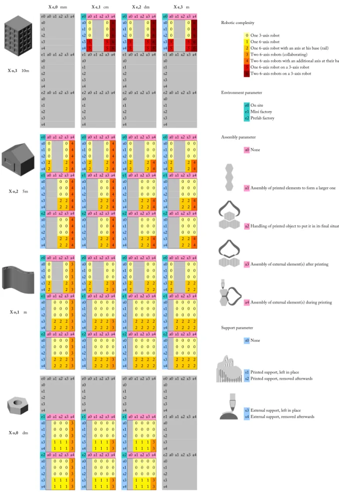
In this chapter we present a method to address the question of concrete printing by robotic extrusion in a general fashion. Several key parameters are highlighted, concerning either the printing itself or its context of use. At stake is a way of comparing diverse procedures to each other, and a cartography of possible approaches. We first introduce a notation system, and investigate the relation between some proposed parameters. Then, a study on robotic complexity is conducted, since it appears to be an important piece of information to choose among several possibilities. The statements and conclusions made here are open to discussion, for we deal with very recent technologies, and because it is not yet clear how the building industry will transform once they become established. The aim is not to put things in separate boxes but to pave the way toward innovative building systems.
On the figures below are depicted three different ways of making use of a similar concrete printing process (similar in their objectives, if not in their actual results), which leads to three very different approaches in terms of building systems. On figure 3.1 is a prototype of a "flat" wall that have been horizontally printed on the floor and then moved to its vertical position.
31
Figure 3.1: Flat wall (Democrite project, 2015)
Such a strategy allows great geometrical freedom for thin 2.5 D structures, as it takes advantage of the smallest dimension of the object and gets rid of the main difficulty of a direct printing : height. However, from a structural design perspective, the loading that corresponds to the handling of the object is likely to be the worse case scenario, and therefore to spoil the attainable lightness of the wall. Figures 3.2 and 3.3 depict an interesting idea proposed by the WASP Project1 which consists in assembling adequately designed components, mixed with steel bars,
to form an ultra-light composite beam, see also [5]. Figure 3.4 and Figure 3.5 show a viable way of printing a concrete mould that is to be filled with UHPFC2 [28]. The unused parts between the tubes are removed afterwards keeping only a very light tubular space-truss structure,here a load-bearing pillar. Those three examples of what is called "indirect" printing reveals some possibilities offered by concrete printing.
The aim of present work is to explicitly characterize the set of possible building systems using concrete printing, and the subsequent associated robotic complexity. Many parameters can be
1https://www.3dwasp.com/en/ 2https://www.xtreee.eu/
Figure 3.2: Externally reinforced beam (WASP, 2015)
33
Figure 3.4: Mould for a space truss (XtreeE, 2016)
considered due to the complexity of such processes. One of them, which is from the traditional 3D-printing industry, can be the printing support. It is well known that one can print an additional material, called support material, in order to reach specific geometries. This support is to be removed in a subsequent step. At large scale, however, the pertinence of such an approach needs to be compared with the use of external supports like falseworks. The flat wall example on Figure 3.1 can be seen as the use of a "flat" support, whereas the example on Figures 3.4 and 3.5 makes use of no external support. Removable concrete parts can be considered as printed support.
This can be generalized by listing the families of possible external supports, as depicted in Figure 3.6. With the exact same printing process, i.e. mortar extrusion, controlled with a 6-axis robot, and varying only the type of external support, one can obtain very different systems, and diverse attainable forms. This analysis highlights the need for additional considerations, for instance regarding assembly. Indeed, if direct printing without external support can be done without bringing any external part, or assembling elements, a multiple printing necessarily entails an assembly step. Likewise, a collaborative printing, where external supports are brought
35
Figure 3.6: Variation of external support parameter. (a) No support ; (b) Flat support ; (c) Curved support ; (d) Multiple supports ; (e) Assembled supports
during the extrusion step can be considered as including an assembly step. Pointing out these differences between building systems is critical to correctly anticipate the associated complexity, technological barriers and to estimate the cost of a project. In addition, a given constructive result can be obtained by cleverly getting around an obstacle - working on the building system as a whole, preferably than developing overly complicated processes which will struggle to achieve industrial implementation.
3.1
Key assumptions
Following the previous intuitive considerations on the qualification of concrete printing building systems, the problem reveals itself as a parametrisation matter. In this chapter, we introduce a notation system, based on the most critical parameters to be considered, and an example of using such notation in order to compare building systems in terms of robotic complexity. Since a parametrisation needs to be as concise and exhaustive as possible, we reduce our problem based on the following hypotheses.
Cementitious paste extrusion. Our analysis is limited to processes engaging cementitious material extrusion, that is to say a system of shaping cementitious paste, mortar or concrete by flowing it out through a moving opening, as described in chapter 2. Such processes include at least a mixing step, a transport step (pumping) and a shaping step. We include in this definition the recent 3D printing of concrete as well as contour-crafting method, but also the older technique of slip-forming. The difference between layered extrusion and slip-forming is treated here as a difference of "extrusion scale" (parameter xe, see 3.2.1 below). Extrusion scale
for slip-forming is usually around 1/10 of the printed object size, whereas this number is lower for layered extrusion processes (e.g. around 1/1000 for the example depicted on Figures 3.4 and 3.5). Since we will be dealing with printed support material, it will not necessarily be extruded and/or cementitious but could also include clay, polymer, or any useful material. However what is considered to be the "main" printed material has to make use of cement. Our analysis is limited to extrusion processes, hence excluding other additive manufacturing techniques like
3.1. Key assumptions 37
stereo-lithography or powder bed-based printing Yet, the proposed system of notation remains open for generalization, and because some of these AM techniques have recently been proposed at large-scale, it would be useful to conduct a similar investigation.
Extrusion speed. One of the critical aspects of concrete 3D-printing is the extrusion speed, more precisely the speed of the nozzle shaping the paste. Since this quantity is directly linked to the printed concrete behaviour, our previous experiences have shown it to be scale-dependent [31]. As a matter of fact, if a large quantity of concrete is being extruded, e.g. by slip-forming, the only way to get it chemically and mechanically sound will be to give enough time for the setting to happen. That is why such techniques traditionally exhibits slow nozzle speeds, typically around a few meters per day. On the contrary, when extruding mortar laces around 1 mm, it is preferable to keep a relatively high-flow pumping system while increasing the nozzle speed, up to several hundreds of millimetres per second. The main reason for it being that such precise printing must be as quick as possible to be implemented in the building industry. Therefore we have chosen not to take the nozzle speed as a parameter in this chapter, but rather to consider an extrusion scale parameter, which is directly related to the nozzle speed under the present assumptions, and more pertinent to characterize building systems in terms of precision. In this context, if one would want to use a relevant speed parameter, it would have to be taken from the whole building system, and not limited to the extrusion step.
Maximum automation : limited human intervention. The technologies of interest in this paper take part in the global movement towards automation. Hence, we suppose that any human intervention in the framework is limited to handling or gathering few, simple, small elements. When robotic speeds are high enough, no human interaction is planned for security reasons.
Robotic system. The shaping step is conducted by a robotic system, going from gantry cranes to more complex robots, such as 6-axis. If the nozzle itself can include robotics, like smoothing or cutting devices, it is considered as a secondary system, while the device moving
the nozzle is called primary. A third robotic system can intervene after printing, for instance to handle large or special printed elements. Only if such actions are taken during printing phase, this system is included in the primary one.
3.2
Classification
3.2.1
Main parameters
A given set of building systems is denoted by enumerating the parameters it is concerned with:
xnoxme eiajsk... (3.1)
Where pn stands for the nth version of parameter p. The parameters are indeed divided into
categories, explained below. The two parameters xo and xe are scale parameters, respectively
about the printed object and the extrusion, while the parameters e, a, and s respectively concern printing environment, assembly and support. The notation is not length-constrained, for instance the set e0 includes every building system consisting in on-site printing, while
the sub-set e0s0 corresponds to all on-site building systems making use of no support for the
printing. We detail below the numbered versions of theses main parameters. The division made here, as well as the indicative values of parameters, are gathered from the literature and the own experience of the authors, while being subject to change.
Object Scale xo This is one of the main parameter to take into account, for it will strongly
orient the decisions taken about a system. It deals with the size of what is printed. We divide it in four versions.
x0
o (dm) - Printed object of size less than a meter, typically a connection or a voussoir x1
o (m) - Constructive element of size around 1-4 m, typically a beam, column or slab. x2
o (dam) - Object around 5-10 meters, typically a living unit or a house. x3
3.2. Classification 39
Extrusion Scale xe This parameter is a characteristic size of what is extruded. Depending
on the process it can be a nozzle diameter, a mortar lace section, or the final thickness of a printed layer. Again it is divided in four scales, taken from literature and our experience to correspond to four diverse material behaviours.
x0
e (mm) - e.g. a thickness layer less than 8mm x1
e (cm) - e.g. a thickness layer between 8mm and 5cm x2
e (dm) - e.g. a thickness layer between 5cm and 30cm x3
e (m) - e.g. a thickness layer above 30cm
Environment e We have extracted three possibilities concerning printing environment. The first one e0 corresponds to a direct printing on-site and without any additional handling of the
object. The second one e1 refers to a printing done in a controlled environment (temperature,
hygrometry, ...) thanks to a light/mobile structure deployed on construction site. The last one
e2 is a traditional prefab factory, imposing handling and transport of the printed object.
e0 On-site(direct printing)
e1 Mini factory (indirect)
e2 Prefab factory (indirect)
Assembly a As seen above, a building system using concrete printing can include some assembly step. We define this term as the action of bringing a macroscopic element by an external device, either during or after printing. This means we do not consider false-work as an assembly step (but as a support, see below). The term "macroscopic element" is opposed to "inclusions" that can be mixed to the extruded mortar, like polystyrene beads or fibres. In that specific case we consider that the secondary robotic device (printing head) is in charge and do not treat it as an assembly step. The assembly step is conducted either by human workers or a third robotic device. There are four types of assembly in our classification, summed up in Table 3.1.
a0 No assembly a1 Assembly of printed elements to form a larger one a2 Handling of printed object to put it in its final situation a3 Assembly of external element(s) after printing a4 Assembly of external element(s) during printing
![Figure 2.1: Principle of building systems using contour crafting, published in [40]](https://thumb-eu.123doks.com/thumbv2/123doknet/2604509.57452/23.892.110.808.94.432/figure-principle-building-systems-using-contour-crafting-published.webp)
![Figure 2.6: Concept of a rotating nozzle to avoid twisting of rectangle laces, published in [9]](https://thumb-eu.123doks.com/thumbv2/123doknet/2604509.57452/33.892.134.760.93.509/figure-concept-rotating-nozzle-avoid-twisting-rectangle-published.webp)
![Figure 2.7: Cantilevering layers of extruded filament, published in [9]](https://thumb-eu.123doks.com/thumbv2/123doknet/2604509.57452/34.892.113.792.82.469/figure-cantilevering-layers-extruded-filament-published.webp)
![Figure 2.11: Building system for towers and columns with a polar extrusion process, published in [41]](https://thumb-eu.123doks.com/thumbv2/123doknet/2604509.57452/40.892.234.669.258.935/figure-building-towers-columns-polar-extrusion-process-published.webp)
![Figure 2.12: TU Eindoven Bicycle bridge, published in [10]](https://thumb-eu.123doks.com/thumbv2/123doknet/2604509.57452/44.892.99.795.84.500/figure-tu-eindoven-bicycle-bridge-published.webp)