an author's https://oatao.univ-toulouse.fr/27098
https://doi.org/10.1109/MAES.2019.170208
Vilà-Valls, Jordi and Navarro, Monica and Closas, Pau and Bertinelli, Massimo Synchronization challenges in deep space communications. (2019) IEEE Aerospace and Electronic Systems Magazine, 34 (1). 16-27. ISSN 0885-8985
INTRODUCTION
Deep space missions keep pushing for new frontiers affecting a wide spectrum of disciplines. To support the scientific achieve-ments expected from new missions, communication technology is being pushed towards its limits [1]. A need to increase communi-cation links data rate as well as to lower the operative signal-to-noise ratio (SNR) are identified. The adoption of advanced coding schemes such as turbo codes and low-density parity-check (LDPC) codes (e.g., Consultative Committee for Space Data Systems (CC-SDS) standards) allows receivers to operate at lower SNRs. How-ever, in order to exploit the full potential of the coding gain, the receiver must be able to acquire and track a signal with a SNR much lower than expected in nominal conditions of state-of-the-art systems. The target operating point is given by the candidate LDPC codes [2], where the codeword error rate is set to WER ≤ 10–5, achieved at the bit energy to noise density ratio E
b/N0 ≥ 5.2 dB, ≥ 3.6 dB for LDPC(128,64) and LDPC(256,128), respectively. In [3] the first receiver bottleneck related with frame synchroni-zation, a functionality required previous to channel decoding, was identified. Even though frame synchronization enhancements were proposed beyond standard correlation techniques [3], [4], [1], it was recommended to increase the synchronization word length in or-der to achieve the target performance. The recommendation was recently adopted by the CCSDS. In this work, the focus lies on the receiver synchronization stages (i.e., acquisition and tracking). Not only from a research standpoint, but also for the design of next gen-eration Telemetry Tracking & Command (TT&C) transponders, it is of capital importance to understand the performance limitations of state-of-the-art deep space communications architectures, clearly identifying possible bottlenecks and the synchronization stages (i.e.,
acquisition and tracking) to be improved. Digital carrier and timing synchronization have been an active research field for the past three decades in applications such as satellite-based positioning or terres-trial wireless communications systems. In those scenarios, the limi-tations of standard delay, frequency, and phase-locked loop (delay-locked loop, frequency-(delay-locked loop (FLL), and phase-(delay-locked loop (PLL), respectively) architectures have been clearly overcome by Kalman filter (KF) based solutions [5], which provide an inherent adaptive bandwidth, robustness, flexibility, and an optimal design methodology. Despite the advances in the field, synchronization ar-chitectures for deep space communications links, implemented in current TT&C transponders, still rely on well-known conventional architectures, which may be insufficient if limits are pushed to ex-tremely low SNR or harsh propagation conditions. With the advent of powerful software defined radio receivers and new system de-sign rules, it is now possible to adopt new robust architectures that may enable going beyond the performance and reliability provided by legacy solutions.
This contribution deals with the synchronization problem in deep space telecommand (TC), much more challenging in terms of system requirements than its telemetry counterpart, due to onboard processing and implementation constraints. First, we provide a thor-ough analysis to identify the performance limits of standard syn-chronization techniques; then, we show the possible performance improvements (and limitations) of innovative state-of-the-art acqui-sition and tracking architectures. Namely, we discuss: (i) fast Fou-rier transform (FFT)-based carFou-rier acquisition, (ii) FLL-assisted PLL and KF-based carrier tracking schemes, (iii) FFT-aided subcarrier tracking, (iv) coherent carrier/subcarrier tracking, and (v) noncoher-ent timing synchronization to avoid the subcarrier stage.
SIGNAL MODEL
Deep space communication, and in particular planetary explora-tion missions, require dealing with signals, such as in the telecom-mand link, with a very low SNR. In this case, the signal is gener-ated by modulating a carrier with a subcarrier, in turn modulgener-ated by data. The resulting modulation, entailing a residual carrier, is commonly referred to as pulse code modulation (PCM)/phase-shift keying (PSK)/phase modulation (PM) [6]. The real-valued pass-band model for the transmitted signal is given by,1
1 This signal (1) usually includes a ranging component, but it was
ex-cluded since it was irrelevant for this work.
Authors’ current addresses: J. Vilà-Valls, M. Navarro, Statistical Inference for Communications and Positioning Department, Centre Tecnològic de Telecomunicacions de Catalunya (CTTC/ CERCA), 08860, Barcelona, Spain, E-mail: ({jvila, mnavarro}@ cttc.cat). P. Closas, Northeastern University, Boston, MA, USA. M. Bertinelli, European Space Agency, Noordwijk, The Netherlands.
Review handled by D. Ciuonzo.
Synchronization Challenges in Deep Space Communications
Jordi Vilà-Valls, Monica Navarro, Centre Tecnològic de Telecomunicacions de
Catalunya, Barcelona, Spain
Pau Closas, Northeastern University, Boston, MA, USA
( )
sin 2(
c c ( )sin 2(
sc sc,0)
c,0)
,s t =A πf t m d t+ πf t+φ +φ (1)
where A is the signal amplitude, fc is the carrier frequency, ϕc,0 is the
initial carrier phase, mc denotes the modulation index (i.e., 0.2 ≤ mc
≤ 1.4), fsc is the subcarrier frequency, ϕsc,0 is the initial subcarrier
phase, and d(t) is the information data stream non return to zero-level (NRZ-L) PCM encoded as,
( )
k NRZ(
b)
,k
d t =
c p t kT− (2)with ck ∈ {−1, 1}, Tb the symbol period, and pNRZ the pulse wave-form,
)
NRZ 1 . 0 0, otherwise b t T p ∈ = (3)The data rates are in the range 7.8125 sps ≤ Rs ≤ 4 ksps (i.e.,
4,000/2n with n = 0, 1, …, 9). The standard establishes that the
subcarrier frequency (8 or 16 kHz) shall be an integer multiple of the symbol rate. Furthermore, the data stream and subcarrier wave-form shall be coherent in time with coincident zero-crossing, that is, ϕsc,0 = 0. The equivalent complex-baseband signal x(t) is
( ) I( ) Q( ),
x t =x t + jx t (4)
related to the real-valued pass-band signal by
( )
{
( )
j2 f tc}
,s t = ℜ x t e π (5)
where xI(t) and xQ(t) are the real and imaginary parts, respectively.
They can be written as,
( )
(
(
)
)
( ) sin sin 2 , I c sc x t =Ad t m πf t (6)( )
cos(
sin 2(
)
)
, Q c sc x t = −A m πf t (7)where the in-phase component contains the data-bearing signal and the quadrature component contains the residual carrier.
The received signal r(t), which includes the channel propaga-tion impairments, as well as noisy effects introduced by the re-ceiver, is modeled as an additive white Gaussian noise channel in presence of Doppler and phase noise,
( ) ( )
jd( )t noise( )
,( )
~( )
0, 2 , nr t x t eφ +φ n t n t σ
= + (8)
with ϕd(t) the phase evolution associated to the Doppler dynamics and
ϕnoise the phase noise. Note that the initial carrier phase is included in the carrier phase contribution introduced by the channel model, ϕnoise. Additionally, we may have a possible Doppler impact on the data, which has a similar effect as a clock jitter (in terms of sampling jitter). That is, time between signal samples is not constant, affecting the actual symbol period. In a discrete-time signal model, the effect is that the number of samples per symbol varies over time. This ef-fect is known as incommensurate sampling and is not taken into ac-count. It is considered a negligible effect because we can assume a quasi-analog sampled signal commonly available in state-of-the-art transponders, i.e., several thousand times higher than the symbol rate. Also, we may consider the Doppler effect in the subcarrier frequency. We can easily take this effect into account by adding an additional term to the nominal subcarrier frequency as fsc= fsc+δfsc.
A list of parameters for a representative deep space communi-cations scenario is summarized in Table 1.
Table 1.
Parameters Specifications for a Reference Deep
Space Communications Scenario
Parameters Deep Space Scenario (e.g., Exomars Mission)
Modulation type Remnant carrier
Waveform PCM NRZ-L; sine-waveform sc
Modulation index mc = 1.2 rad
Symbol rate Rs = 7.8125 sps to 4 ksps
Carrier freq. fc in X-band
Subcarrier freq. fsc = 8 or 16 kHz
Uplink fc 7145-7190 MHz
Real Doppler on fc ± 400 kHz
Compensated Doppler ± 2 kHz Doppler on fsc ±1 Hz
TYPICAL DEEP SPACE TELECOMMAND RECEIVER
ARCHITECTURE
The block diagram of a typical deep space TC receiver is shown in Figure 1. Note that for the sake of clarity, the complex signal mod-eling is used instead of the quadrature (I&Q) signal decomposition with real and imaginary parts. The transponder is configured to receive a PCM/PSK/PM signal. In this configuration, a subcarrier tracking loop (implemented as a Costas loop) is in place.
CARRIER ACQUISITION
The carrier acquisition scheme is based on the carrier sweeping algorithm at the sending end (ground station) and a second order PLL at the receiver end, with an atan2 discriminator. The PLL error signal will most likely show an erratic behaviour until the swept carrier enters the pull-in range of
the tracking loop. Then, if properly ad-justed, the PLL will lock to the signal.
CARRIER PHASE TRACKING
Once the carrier frequency is acquired the receiver enters the carrier tracking loop, which implements the same sec-ond order PLL initialized to the resting frequency acquired in the previous stage (a higher order filter may also be con-sidered). In this stage, the receiver could eventually reduce its loop bandwidth since the carrier frequency change rate is only due to the spacecraft dynamics, while in the previous stage the change rate is given by the sum of sweep and Doppler rate.
SUBCARRIER PHASE TRACKING
In the presence of a modulated subcar-rier, as is the case for deep space scenar-ios, a subcarrier acquisition and track-ing stage follows the second order PLL. The baseline algorithm is a second order Costas-loop with an atan discriminator. The block diagram is depicted in Figure 1, where the subcarrier switch has to be turned on before passing the signal to symbol timing and demodulation. This module needs to cope with additional Doppler on the subcarrier, not compen-sated by the PLL on the carrier signal.
SYMBOL-TIMING TRACKING
The baseline technique for timing syn-chronization and symbol demodulation
is a second-order data transition tracking loop (DTTL) module, which precedes the matched filter demodulator. The scheme im-plemented for the evaluation of the baseline-receiver is depicted in Figure 1. It is an equivalent implementation of the current state-of-the-art receiver [7]. Particularly, the specific implementation for deep space missions (i.e., NRZ-L encoded data) can be consulted in Figure 2.
CARRIER TO NOISE POWER SPECTRAL DENSITY
ESTIMATION
The baseline receiver also includes a carrier-to-noise-density-ratio (C/N0) estimation algorithm, which provides a useful indi-cator in the receiver state machine and processing modules. The estimator follows the implementation in [8] (block diagram in Figure 1).
Figure 1.
Vilà-Valls et al.
BASELINE DEEP SPACE RECEIVER
PERFORMANCE ANALYSIS
In this section we present the performance analysis of the baseline receiver architec-ture described in the previous section.
We consider a transmitter that gen-erates a binary data structure, followed by the discrete-time modulator that gen-erates the digital signal waveform sam-ples transmitted through the channel. The channel emulator includes additive white Gaussian noise. Notice that for the assessment of the synchronization algo-rithms it is not necessary to implement the specific Transfer Frame data struc-ture or the error control field of 16 parity
bits [9], [10]. It is sufficient to generate a random binary vector and apply the randomizer to ensure the equivalent bit transition condi-tions. Throughout the article we set the receiver target operation point to Es/N0 ≥ 2 with WER ≤ 10–5. Notice that Es refers to the
energy of coded symbols, which for channel coding rates of 1/2 leads to the relation Es/N0 = Eb/N0 – 3 dB.
ACQUISITION
Before introducing the simulation results on carrier acquisition, we first provide a simple preliminary assessment in order to gain insight into the performance limits of the carrier acquisition perfor-mance. Under this setup, the C/N0 takes the form
0 0 , s s C E R N =N α (9)
with α=J m02
( )
c(
2J m12( )
c)
. The results obtained for amodula-tion index mc = 1.2 are shown in Table 2. Taking into account the
loop filter bandwidth BL, we can define the carrier-to-noise ratio
as C/N = C/(N0*BL), with N the noise power. Considering that the
recommended value for C/N shall be equal or higher than 10 dB for a correct carrier acquisition and tracking, one can deduce that the deep space scenarios under consideration present real challenges for low Es/N0 values (< 4 dB) at low symbol rates, even for very narrow loop bandwidths.2 Employing symbol rates as low as 7.125 sps may be required, for instance, in environments of limited vis-ibility due to tumbling or other attitude issues.
Considering specific loop bandwidths and imposing the con-straint C/N ≥ 10 dB, Figure 3 shows for which symbol rates it will not be possible to successfully acquire and track the carrier. The solid red line indicates the Es/N0 = 2 dB threshold.
2 J
k(z) denotes the kth Bessel function of the first kind.
Figure 2.
DTTL symbol timing tracking for NRZ-L PCM encoding.
Table 2.
C/N
0(dB – Hz) for Deep Space Scenarios as a Function of E
s/N
0(dB)
Rs [sps] Es/N0 [dB] −6 −4 −2 0 2 4 6 4,000 29.6 31.6 33.6 35.6 37.6 39.6 41.6 2,000 26.59 28.59 30.59 32.59 34.59 36.59 38.59 1,000 23.58 25.58 27.58 29.58 31.58 33.58 35.58 500 20.57 22.57 24.57 26.57 28.57 30.57 32.57 250 17.56 19.56 21.56 23.56 25.56 27.56 29.56 125 14.55 16.55 18.55 20.55 22.55 24.55 26.55 62.5 11.54 13.54 15.54 17.54 19.54 21.54 23.54 31.25 8.52 10.52 12.52 14.52 16.52 18.52 20.52 15.625 5.51 7.51 9.51 11.51 13.51 15.51 17.51 7.8125 2.5 4.5 6.5 8.5 10.5 12.5 14.5
Next, we discuss the simulation results for the carrier acquisi-tion based on the ground sweeping. The emulaacquisi-tion of the on-ground sweeping is implemented by generating a data stream of an unmodulated carrier. The implementation follows the standard recommendation [6] by implementing a symmetric triangular car-rier sweeping from fmin to fmax. The acquisition process must ensure the carrier sweeping passes twice through the resting frequency of the transponder PLL. As already pointed out, it has been found via simulation that carrier sweeping is not reliable for the deep space scenarios considered in this work, leading to the need for receiver enhancements (i.e., discussed in “Standard Receiver En-hancements”).
CARRIER/SUBCARRIER TRACKING
In this section, we assess the performance of the carrier/subcarrier tracking stage of the receiver. The most challenging scenario cor-responds to the lowest symbol rate. That is, Rs = 7.8125. However,
the system may operate up to 4 ksps. In this analysis, both carrier and subcarrier phase tracking have been found to be a bottleneck for deep space scenarios, being impossible with the baseline re-ceiver architecture to operate at the target Es/N0 = 2 dB and symbol rate Rs = 7.8125 sps. Several tests have been performed to obtain
the receiver operation point limit, which mainly depends on the Doppler rate on the carrier and the residual Doppler on the subcar-rier, and is directly related with the well-known noise reduction versus dynamic range trade-off. To determine such performance limits the following procedure was considered:
1. Carrier phase tracking performance limit. First, several tests were conducted for different symbol rates to see if the carrier phase tracking stage converged to a steady-state regime, using the carrier phase root mean square error (RMSE) and reference lock to decide if the PLL is correctly working or not. From this analysis the minimum symbol rate for each SNR was already determined.
2. Subcarrier phase tracking performance limit. Then, using the same reasoning, it was obtained for several case studies which was the subcarrier tracking Es/N0 versus Rs limit, using
the RMSE in the steady-state regime and the Costas reference lock. It was found that the subcarrier tracking stage was always more restrictive (i.e., higher symbol rate required) than the car-rier tracking stage; therefore, this block is the main driver on the overall system performance for a noncoherent subcarrier architecture.
Using the subcarrier performance limit, which is the most re-strictive, it was verified that the symbol error rate obtained using the whole receiver chain, including the DTTL, was correct. From these results the baseline receiver performance limits were deter-mined. The target scenario considers a Doppler rate on the carrier equal to 30 Hz/s and a residual subcarrier Doppler equal to 1 Hz. Under these conditions, the lowest symbol rate to guarantee per-formance at Es/N0 = 2 dB corresponds to 500 sps. If the Doppler constraints in both the carrier and subcarrier are relaxed (i.e., car-rier Doppler = 1 Hz/s and subcarcar-rier Doppler = 0.1 Hz), the system may work down to 125 sps. We summarize the main findings on the baseline receiver performance limits in Table 3.
From the different results obtained during the baseline receiver performance limits analysis, it is worth highlighting the following remarks: (i) reducing the carrier Doppler rate (for a fixed subcarrier Doppler equal to 1 Hz) does not significantly improve the receiver performance, being the Doppler on the subcarrier the main driver on the system error; and (ii) considerably reducing the Doppler on the subcarrier (i.e., from 1 Hz to 0.1 Hz) the receiver performance improvement is marginal. Then, we conclude that:
C Using enhanced carrier tracking architectures such as a third
order PLL, a Kalman filter, or a FLL-assisted PLL, the ex-pected performance gain is marginal if a noncoherent sub-carrier architecture is considered.
C Considering enhanced tracking strategies such as a
FLL-assisted PLL into the subcarrier, the expected performance gain is also minor. At the limit, the bottleneck on the system performance is now the carrier tracking stage.
C If both receiver enhancements are coupled, at the target
Es/N0 = 2 dB the lower bound on the symbol rate for a correct
Table 3.
Baseline Receiver Lowest Symbol Rate Versus
Required E
s/N
0for a Deep Space Scenario,
Considering a Subcarrier Doppler = 1 Hz and a
Carrier Doppler Rate = 30 Hz/s
Es/N0 [dB]
2 4 6 8 10 12
[sps] 500 125 62.5 31.25 15.125 7.8125
Figure 3.
Estimated required Es/N0 to ensure C/N ≥ 10 dB as a function of symbol
Vilà-Valls et al.
receiver (i.e., baseline receiver with noncoherent subcarrier) performance is obtained at 125 sps.
The last statement is supported by the simulation results in Figure 4, which shows the subcarrier RMSE obtained with a per-fect initial acquisition, a quasi-perper-fect carrier tracking, and a very low subcarrier Doppler. Even with such benign conditions, the subcarrier tracking limit appears at 125 sps.
DATA TRANSITION TRACKING LOOP (DTTL) ANALYSIS
The baseline receiver symbol synchronization is performed with a DTTL. The results discussed in the previous section were obtained with the corresponding DTTL being operative and considering a correct symbol timing initialization. Here we extend the results to the case of steady-state performance. That is, assuming perfect car-rier and subcarcar-rier tracking, and a correct DTTL initialization en-suring that no error propagation comes from previous stages. The performance results are shown in Figure 5, where the symbol error rate (SER) is evaluated for different symbol rates. Clearly, at the lowest symbol rate Rs = 7.8125 sps, the SER follows the theoretical
performance, showing a DTTL correct operation.
Additionally, the symbol error rate obtained with an initial sym-bol synchronization error equal to T/4 is compared to the steady-state performance results in Figures 6 and 7. Two different symbol rates were considered: (i) Rs = 500 sps, being the performance limit
of the baseline receiver for the noncoherent subcarrier architecture, and (ii) Rs = 62.5 sps, being the performance limit for the coherent
subcarrier architecture (see “Standard Receiver Enhancements”). In both cases the DTTL correctly synchronizes within the 128 bits acquisition sequence, indicating that the DTTL is not a bottleneck.
STANDARD RECEIVER ENHANCEMENTS
From the previous analysis of the baseline receiver, it has been found that carrier and subcarrier tracking are a bottleneck for the
Figure 4.
Subcarrier phase RMSE versus symbol rate for the deep space scenario. Carrier Doppler rate = 1 Hz/s, subcarrier Doppler = 0.1 Hz, Bpll = 5 Hz,
BCostas = 5 Hz.
Figure 5.
SER for different symbol rates considering perfect carrier and subcarrier tracking, and correct DTTL initialization.
Figure 6.
SER for Rs = 500 sps considering perfect carrier and subcarrier tracking,
and two DTTL initializations: correct symbol sync and initial symbol sync error = T/4.
Figure 7.
SER for Rs = 62.5 sps considering perfect carrier and subcarrier
track-ing, and two DTTL initializations: correct symbol sync and initial symbol sync error = T/4.
deep space scenario at the target Es/N0 = 2 dB, for the lowest sym-bol rates. In this section we consider some receiver enhancements to overcome the limitations of the standard architecture and ana-lyze their performance.
One of the main challenges for proper receiver operation at the extremely low signal-to-noise ratio is to reduce the noise con-tribution to the tracking loops, which requires reducing the loop bandwidth as much as possible. This is in contrast to having a suf-ficiently large loop bandwidth to increase the pull-in range and allow signal lock. An enhancement aimed at reducing the loop bandwidth at the tracking loops is to improve the acquisition of the corresponding signal; namely, improving the estimate of the rest-ing frequency of the baseline carrier and subcarrier trackrest-ing loops, PLL and Costas loops, respectively. To this end, it is known that FFT techniques are an alternative to acquire the carrier (or subcar-rier) frequency deviations and therefore correct them.
FFT-BASED CARRIER ACQUISITION
In order to reduce the bandwidth of the PLL (or the desired scheme used to track the carrier phase), an FFT can be used to accurately estimate the Doppler shift of the carrier and correct for it at the loop's Numerically-Controlled Oscillator (NCO), in which case sweeping from the ground is not required. The precision of this technique can be adjusted, depending basically on the number of points used in the FFT computation.
In order to validate the implementation and show the perfor-mance of FFT-based carrier tracking acquisition schemes, a set of experiments were conducted, where several FFT points were tested. For each experiment, we average the carrier frequency and carrier phase RMSE over time for different Es/N0 values. It is clear that increasing the FFT size has a notable impact on the ability of
the receiver to lock the carrier signal. Therefore, this technique is very interesting, particularly in scenarios with low SNR at the receiver input.
The evaluation is shown for Rs = 62.5 sps, which corresponds
to the lowest symbol rate that can achieve the target performance at Es/N0 = 2 dB. Since, for the deep space telecommand scenario, we have very low symbol rates, the FFT-aided carrier acquisition technique is very challenging. The results illustrate how the dif-ferent configuration parameters affect the performance. The main parameter affecting performance is the number of FFT points (i.e., between 512 and 8,192), since it determines the accuracy of the frequency estimate. The frequency resolution or frequency bin width is given by the sampling frequency (which is adjusted to the frequency span where the Doppler shift is expected) used by the FFT computation and the number of FFT points. To evaluate this effect, we have considered three different Doppler spans: 500 Hz, 5 kHz, and 100 kHz. For each scenario, each Monte-Carlo re-alization randomly generates the Doppler shift between 0 and the Doppler span. The second parameter is the number of FFT blocks (number of performed FFTs) used to estimate the periodogram (i.e., 1 to 10 averaged FFT blocks). Increasing the number of FFT blocks reduces the variance of the estimated periodogram. Besides the constraints on memory and processing power the transponder architecture may impose, the maximum number of FFT blocks is determined by the channel coherence.
For instance, for the lower Doppler span of 500 Hz, 512-point FFT results in a frequency bin of approximately 2 Hz. However, when the Doppler span is 100 kHz we need to increase the number of FFT-points to 8,192 to obtain a similar frequency bin resolution. We summarize the FFT related parameters in Table 4.
The results obtained in several configurations for demanding scenarios are shown in Table 5. We declare a misacquisition the
Table 4.
FFT Related Parameters
MaximumDoppler Shift FFT Sampling Frequency FFT Size Frequency Bin Doppler Shift in an FFT Block
Maximum Number of FFT Blocks 500 Hz 1 kHz 512 1.95 Hz 7.68 Hz 1 1,024 0.97 Hz 15.36 Hz 1 512 19.53 Hz 0.76 Hz 25 1,024 9.76 Hz 1.53 Hz 6 5,000 Hz 10 kHz 2,048 4.88 Hz 3.07 Hz 1 4,096 2.44 Hz 6.14 Hz 1 8,192 1.22 Hz 12.3 Hz 1 512 390.62 Hz 0.04 > 10,000 1,024 195.31 Hz 0.08 Hz > 2,500 100 kHz 200 kHz 2,048 97.65 Hz 0.15 Hz 635 4,096 48.82 Hz 0.31 Hz 159 8,192 24.41 Hz 0.61 Hz 39
Vilà-Valls et al.
cases where the error is much larger than the frequency resolu-tion (> 100 Hz, in which cases the PLL is not able to lock) and compute the RMSE over the successful acquisition realizations. We can conclude that the FFT approach enables successfully ac-quisition of the carrier frequency for a large Doppler span without the need for carrier sweeping, thus enabling narrowing of the PLL loop bandwidth for successful lock at low Es/N0 (or equivalently low C/N0).
FFT-AIDED SUBCARRIER TRACKING
The concept is similar to the one applied for the carrier frequency acquisition. An FFT is applied to determine, with adjustable preci-sion, the Doppler deviation on the subcarrier frequency. Then, this
estimate is used to improve the resting frequency of the baseline Costas loop. By doing so, the loop bandwidth can be further re-duced, thus being able to operate at lower SNR values. Figure 8 de-picts the block diagram of the subcarrier tracking including this en-hancement. Besides the number of FFT points, in order to increase the precision of this technique, downsampling can be also used.
The same analysis conducted in the previous section has been done also for the third order PLL + Costas-FFT + DTTL case, with the main results summarized in Table 6. Comparing these results with the performance limits obtained for the baseline receiver ar-chitecture, it is clear that using the FFT for better initialization of tracking loops improves the system performance by lowering the required Es/N0 from 12 to 10 dB. However, it is still far from the 2 dB target.
Table 5.
Results for the FFT-Aided Carrier Acquisition for a Deep Space Scenario
Es/N0 [dB] 10 6 4 2 Results for 500 Hz FFT size/blocks 512/1 512/1 512/1 512/1 Number of realizations 50 50 50 50 Number of misacquisitions 2 6 5 7 RMSE 5.33 Hz 5.31 Hz 5.55 Hz 5.48 Hz RMSE (including failures) 77.55 Hz 104.88 Hz 109.81 Hz 107.36 Hz Results for 5 kHz FFT size/blocks 512/10 8,192/10 512/10 8,192/10 512/10 8,192/10 512/10 8,192/10 Number of realizations 50 50 50 50 50 50 50 50 Number of misacquisitions 13 14 13 13 14 17 13 15 RMSE 17.9 Hz 8.07 Hz 18.19 Hz 9.14 Hz 18.79 Hz 8.65 Hz 16.79 Hz 8.06 Hz RMSE (including failures) 1.38 kHz 1.56 kHz 1.19 kHz 1.36 kHz 1.71 kHz 1.57 kHz 1.34 kHz 1.82 kHz Results for 100 kHz FFT size/blocks 8,192/1 8,192/10 8,192/1 8,192/10 8,192/1 8,192/10 8,192/1 8,192/10 Number of realizations 50 50 50 50 50 50 50 50 Number of misacquisitions 3 0 35 0 43 0 46 3 RMSE 22.96 Hz 23.67 Hz 19.28 Hz 22.70 Hz 19.86 Hz 24.57 Hz 19.81 Hz 21.89 Hz RMSE (including failures) 31.58 kHz 23.67 Hz 76.31 kHz 22.70 Hz 89.32 kHz 24.57 Hz 83.48 kHz 5.78 kHz
FLL-ASSISTED PLL AND KF-BASED CARRIER TRACKING
SCHEMES
We have seen that the carrier tracking in the baseline receiver, per-formed with a second order PLL, is compromised in the considered deep space scenarios by the noise reduction versus dynamic range trade-off. That is, the PLL has to operate at very low SNR, which implies using a very narrow bandwidth, but the incoming signal is affected by a moderate carrier Doppler rate, being more suitable to cope with such dynamics to increase the loop bandwidth. As a result, the filter is not able to meet both requirements and loop does not lock to the incoming signal's carrier phase. To overcome these limitations two techniques are considered: (i) FLL-assisted PLL and (ii) Kalman filter-based carrier tracking. For both methods we assume an FFT-based carrier acquisition, and the subcarrier track-ing is evaluated considertrack-ing the FFT-aided Costas loop to improve the acquisition and tracking in the presence of residual Doppler in the subcarrier.
The FLL-assisted PLL is investigated in order to be able to reduce the PLL bandwidth while keeping track of the Doppler dy-namics. The main idea is to use a second order FLL to sequentially estimate the signal's frequency, which is then fed to a third order PLL. In this case, the PLL has to cope with a reduced dynamics
signal, being able to use a lower bandwidth and improving the noise reduction. From the results obtained, the FLL is not perform-ing correctly at low SNR, therefore the frequency aidperform-ing is not im-proving the standalone PLL performance for the target scenarios. The fact that the FLL-assisted PLL carrier tracking is not robust to low SNR is well known in the literature, because the FLL dis-criminators are much more sensitive to noise (compared to phase discriminators) due to the inherent noise amplification. This is the reason why these schemes are usually discarded to operate at low SNR and are not of interest in this study.
Table 6.
Third Order PLL + Costas-FFT + DTTL Performance
Limits for a Deep Space Scenario, Considering a
Subcarrier Doppler Initialized with the FFT and a
Carrier Doppler rate = 30 Hz/s
Es/N0 dB
2 4 6 8 10
[sps] 125 62.5 31.25 15.125 7.8125
Figure 8.
FFT-aided Costas loop. An FFT is used to acquire the Doppler on the subcarrier and then a standard Costas loop is used, whose resting frequency is cor-rected by fFFT.
Vilà-Valls et al.
It has been shown in the literature that the standard PLL limita-tions are usually overcome by KF-based carrier tracking solulimita-tions. It is well known that a standalone PLL is equivalent to a KF with a priori fixed gain (i.e., fixed bandwidth); therefore, it is expect-ed that a KF performs at least as well as its PLL counterpart. One of the main advantages of the KF in its standard form is that the Kalman gain is sequentially and optimally computed, which can be seen as an inherent adaptive bandwidth of the filter. The time-varying Kalman filter gain is the equivalent of the constant PLL loop filter coefficients, and the state prediction acts as an integra-tor, being equivalent to the NCO block in the standard PLL. The optimal bandwidth computation performed by the KF significantly increases the computational complexity and the required system knowledge when compared to the simplicity of the PLL, where only the loop bandwidth must be specified. That is the reason why the latter is still considered the method of choice in many applications.
We show in Figure 9 the standard adaptive KF (i.e., adaptive referring to the adaptive computation of the discriminator phase noise variance from the sequential C/N0 estimation) carrier phase RMSE, obtained for the Rs = 125 sps, compared to the second and
third order PLLs. Although the performance gain obtained with the adaptive KF is clear from the results in this case study, the com-putational complexity is significantly higher and the filter tuning much more complex than for the standard PLL, where only the bandwidth and order of the filter are specified [5]. The adaptive bandwidth behavior of the KF is shown in Figure 10.
COHERENT CARRIER/SUBCARRIER TRACKING
The solution to overcome and improve the limitations of noncoher-ent carrier/subcarrier tracking approaches and go below the Rs =
125 sps achieved with the enhanced FFT-based Costas subcarrier tracking, is to consider a coherent carrier/subcarrier architecture.
Even evaluating the baseline receiver assuming a subcarrier Doppler of 0 Hz (i.e., coherent carrier/subcarrier), the system can-not operate at the lowest symbol rate. However, good performance is achieved for Rs = 62.5 sps, which considerably improves
perfor-mance with regard to the FFT-aided Costas loop. Yet, the required Es/N0 = 10 dB to be able to operate at Rs = 7.8125 sps. Table 7
sum-marizes the results. In this case, the main driver on the receiver per-formance limit is no longer the subcarrier (i.e., the Costas bandwidth can be reduced from 15 Hz to 2 Hz) but the carrier tracking stage.
The simulated SER is compared in Figure 11 for different sym-bol rates. These results confirm the performance limits shown in
Table 7.
Baseline Receiver Performance Limits for a Coherent
Subcarrier, Subcarrier Doppler = 0 Hz and Carrier
Doppler Rate =30 Hz/s
Es/N0 dB
2 4 6 10
[sps] 62.5 31.25 15.125 7.8125
Figure 9.
Carrier tracking performance for Rs = 125 sps, considering a standard
adaptive KF, second, and third order PLLs.
Figure 10.
Adaptive KF bandwidth versus constant PLL bandwidth.
Figure 11.
SER performance for the deep space scenario considering a third order PLL + Costas, and a coherent subcarrier.
Table 7 and are in line with the results obtained for the FFT-based Costas scheme.
To complete the analysis and characterization of the coherent carrier/subcarrier architecture, the DTTL performance (consider-ing the SER for the whole receiver chain) with a correct tim(consider-ing synchronization initialization is compared to the case where the initial synchronization error = T/4 in Figure 12. Note that the same results are valid for other timing initializations. As was shown in the standalone DTTL performance analysis, the performance ob-tained with both perfect and imperfect initializations is equivalent.
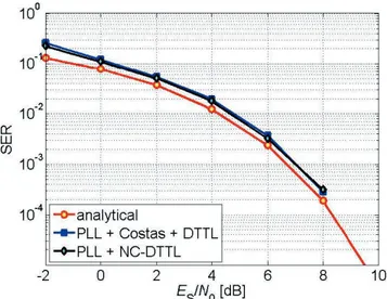
NONCOHERENT TIMING SYNCHRONIZATION
An alternative approach to improve the overall receiver architec-ture performance is the Noncoherent
DTTL (NC-DTTL). The main idea of the NC-DTTL is to avoid the subcar-rier tracking stage by using a nonco-herent architecture, which is shown in Figure 13. Notice that even if the subcarrier tracking stage is avoided, the input to the NC-DTTL is the output of the carrier tracking stage (i.e., PLL); therefore, the limitations of this first stage are not solved with such architec-ture. In other words, using a coherent subcarrier, it has been shown that the third order PLL performance limit at Es/N0 = 2 dB is given by the Rs = 62.5
sps case; thus, using the NC-DTTL the performance limit is the same.
The steady-state performance comparison of the NC-DTTL with the standard DTTL for the coherent archi-tecture and Rs = 62.5 sps is shown in
Figure 14, where again it is clear that the performance obtained with both ar-chitectures is equivalent.
CONCLUSIONS
An assessment of the baseline baseband receiver functionalities has been carried out, supported by performance simulations based on a detailed link level simulation software model. The following bottlenecks are identified:
1. Carrier acquisition (performed on the unmodulated carrier signal) does not represent a bottleneck for sufficiently high C/N0. For deep space scenarios, the carrier sweeping limits the performance at low symbol rate at the target Es/N0 = 2 dB. An enhanced carrier acquisition scheme based on spectral estimation techniques (it requires FFT processing, averaging, and simple threshold
detec-Figure 13.
Noncoherent DTTL.Figure 14.
DTTL versus NC-DTTL considering a coherent subcarrier and Rs = 62.5
sps.
Figure 12.
SER performance for the deep space scenario considering a third order PLL + Costas architecture, and a coherent subcarrier for Rs = 62.5 sps.
Vilà-Valls et al.
tion) can relax the requirements on the carrier loop enforced by the on-ground sweeping procedure. Such an approach has several advantages: (i) FFT-based carrier acquisition does not require on-ground sweeping, (ii) allows faster acquisition, and (iii) can reach lower estimation errors on carrier frequency.
2. Carrier and subcarrier tracking are the critical bottleneck in order for the receiver to operate at the target Es/N0 for the se-lected deep space scenarios. From the evaluated enhanced ap-proaches, FFT-aided Costas subcarrier acquisition and tracking provides gains in the low SNR region, yet they do not meet the target Es/N0 at the low rate scenario.
3. An alternative solution that affects the transmitter side, which implies implementing a coherent carrier and subcarrier gen-eration, would significantly improve the receiver synchroni-zation performance. In this line, a noncoherent demodulation that avoids subcarrier tracking has been evaluated, showing promising results. The noncoherent scheme is compared to the coherent receiver that performs subcarrier tracking by means of a Costas loop and the same symbol timing tracking and de-modulation scheme. Both schemes achieve very similar per-formance. The former avoids subcarrier tracking but requires implementing two DTTL branches.
To summarize, the assessment of the code impact on the re-ceiver functionalities and identification of bottlenecks in the tran-sponder synchronization schemes indicate that both acquisition and tracking loops must be upgraded to fully exploit the potential gains that more powerful coding schemes bring to telecommand in space communications. Current standard configurations will not be able to operate at the lower link budget for the lowest rate op-erational modes.
ACKNOWLEDGMENTS
This work has been supported by the Spanish Ministry of Econo-my and Competitiveness through project TEC2015-69868-C2-2-R
(ADVENTURE), ESA's Basic Technology Research Programme entitled Next Generation Uplink Coding Techniques (NEXCODE), Contract No. 4000111690/14/NL/FE, and by the Government of Catalonia under Grant 2014–SGR–1567.
REFERENCES
[1] Baldi, M., Bertinelli, M., Chiaraluce, F., Closas, P., Dhakal, P., Garello, R. et al. State-of-the-art space mission telecommand receivers. IEEE
Aerospace and Electronic Systems Magazine, Vol. 32, 6 (2017), 4–15.
[2] CCSDS. Next generation uplink. green book, CCSDS 230.2-G-1. Jul. 2014.
[3] Baldi, M., Bertinelli, M., Chiaraluce, F., Closas, P., Garello, R., Ma-turo, N. et al. Nexcode: Next generation uplink coding techniques. In
Proceedings of the 7th ESA International Workshop on Tracking, Te-lemetry and Command Systems for Space applications (TT&C), Estec,
Noordwijk, The Netherlands, Sep. 2016.
[4] Pfletschinger, S., Navarro, M., and Closas, P. Frame synchronization for next generation uplink coding in deep space communications. In
Proceedings of the IEEE Global Communications Conference, Exhi-bition & Industry Forum (GLOBECOM 2015), San Diego, CA, Dec.
2015.
[5] Vilà-Valls, J., Closas, P., Navarro, M., and Fernández-Prades, C. Are PLLs dead? A tutorial on Kalman filter-based techniques for digital carrier synchronization. IEEE Aerospace & Electronic Systems
Maga-zine, Vol. 32, 7 (2017), 28-45.
[6] ECSS. Radio frequency and modulation. ECSS-E-ST-50-05C Rev.2, Oct. 2011.
[7] Hamkins, J., and Simon, M. K. Autonomous Software-Defined Radio
Receivers for Deep Space Applications. New York: Wiley, 2006.
[8] Monk, A. M. Carrier-to-noise power estimation for the block V receiv-er. JPL TDA Progress Report 42 (1991): 106, Tech. Rep., Oct. 1991. [9] ECSS. Space data links—Telecommand protocols, synchronization
and channel coding. ECSS-E-ST-50-04C, Jul. 2008.
[10] CCSDS. TC synchronization and channel coding, blue book. CCSDS 231.0-B-3, Sep. 2017.