HAL Id: pastel-00001383
https://pastel.archives-ouvertes.fr/pastel-00001383
Submitted on 25 Oct 2005HAL is a multi-disciplinary open access archive for the deposit and dissemination of sci-entific research documents, whether they are pub-lished or not. The documents may come from teaching and research institutions in France or abroad, or from public or private research centers.
L’archive ouverte pluridisciplinaire HAL, est destinée au dépôt et à la diffusion de documents scientifiques de niveau recherche, publiés ou non, émanant des établissements d’enseignement et de recherche français ou étrangers, des laboratoires publics ou privés.
nanostructured carbons
David Langohr
To cite this version:
David Langohr. A study on hydrogen storage through adsorption in nanostructured carbons. En-gineering Sciences [physics]. École Nationale Supérieure des Mines de Paris, 2004. English. �NNT : 2004ENMP1249�. �pastel-00001383�
Collège doctoral
N° attribué par la bibliothèque
|__|__|__|__|__|__|__|__|__|__|
T H E S E
pour obtenir le grade de
Docteur de l’Ecole des Mines de Paris
Spécialité “Energétique”
présentée et soutenue publiquement par
David LANGOHR
le 21 octobre 2004
ÉTUDE DU STOCKAGE D’HYDROGÈNE PAR ADSORPTION DANS
DES CARBONES NANOSTRUCTURÉS /
A STUDY ON HYDROGEN STORAGE THROUGH ADSORPTION IN
NANOSTRUCTURED CARBONS
Directeurs de thèse : Patrick ACHARD et Laurent FULCHERI
Jury :
M. Edward McRAE...Président / Rapporteur M. Pierre LE CLOIREC ...Rapporteur M. Gilles FLAMANT... Examinateur M. Alain RAVEX... Examinateur M. Laurent FULCHERI... Examinateur M. Patrick ACHARD ... Examinateur
A toi Amanda,
Nuit tropicale et caressante, Où, sur la mer, bondissant, Notre navire au front puissant Trace une frange éblouissante. Sur la route qu’il s’est frayée, Quelquefois le regard rêveur Voit flamboyer une lueur. C’est une baleine, effrayée. Puis, quand vient l’aube, la rosée, Sous l’éclat du soleil
Fusant de biais au ciel vermeil, Sur les cordages s’est posée. Et sur l’immense piste verte, A pleines voiles, en longs remous, Nous cinglons toujours devant nous, Sur la piste immense et déserte.
Cette thèse s’est déroulée dans le laboratoire du Centre d’Energétique de l’Ecole des Mines de Paris sur le site de Sophia-Antipolis. Je remercie Didier Mayer, Directeur-Adjoint du CENERG, de m’avoir accueilli dans son laboratoire.
Merci à mes deux directeurs de thèse, Patrick Achard et Laurent Fulcheri, responsables scientifiques au CENERG. Il n’est pas forcément évident de s’entendre avec son directeur de thèse. J’ai eu la chance - et le challenge - d’en avoir deux ! De tempéraments fort différents, mais qui - fort heureusement - se révélèrent complémentaires dans mes progressions et mes enlisements… Qu’ils trouvent ici l’expression de toute ma gratitude pour leur écoute respective, tant scientifique qu’humaine.
Merci à Edward McRae, Directeur de Recherche du groupe Matériaux à squelette carboné au laboratoire CNRS de Nancy, d’avoir bien voulu tenir le double rôle de rapporteur de ce manuscrit et de président du jury pendant la soutenance. Au delà de ces ‘missions’, je tiens à remercier Ted pour la qualité de nos échanges ces dernières années. Son regard critique et son recul tout au long de mon cheminement m’ont aidé à accepter que le résultat final ne devait pas être une fin en soi. Toute démarche scientifique prend racine dans l’exigence de la fiabilité d’une mesure.
Merci au Professeur Pierre Le Cloirec, responsable du département Systèmes Energétiques et Environnement de l’Ecole des Mines de Nantes, d’avoir également accepté la fonction de rapporteur de ce travail et d’avoir participé au jury de ma thèse. A sa suggestion de deuxième thèse je réponds que je préfère en rester au bon souvenir de celle-ci !
Merci à Alain Ravex, Directeur Technique de la Division des Techniques Avancées d’Air Liquide à Sassenage, et au Professeur Gilles Flamant, Directeur de Recherche et directeur du laboratoire CNRS PROMES (PROcédés, Matériaux et Energie Solaire) à Odeillo, qui ont bien voulu faire partie de mon jury de thèse. Je n’ai malheureusement pu profiter de leur présence lors de la soutenance - qui heureusement ne sera pas partie remise ! Néanmoins, j’espère avoir l’occasion de travailler avec des personnes de leur compétence dans les années à venir.
Merci à Sandrine Berthon-Fabry et José Gonzalez-Aguilar pour leur disponibilité et leurs compétences complémentaires qui m’ont été d’un grand recours. Ils ont facilité la cohésion du travail contractuel et scientifique entre les directeurs de thèse et le doctorant.
Merci à Arnaud Rigacci pour son aide précieuse sur le SAXS et son enthousiasme quotidien, ainsi qu’à Rudolf Metkemeijer, qui fut un des initiateurs de ce projet sur l’étude du stockage d’hydrogène et sans lequel il n’aurait jamais eu lieu. Tous deux se sont toujours montrés à l’écoute.
Merci également à toute l’équipe permanente du CENERG de Sophia-Antipolis qui contribue quotidiennement au bon fonctionnement du laboratoire, au niveau informatique, technique ou logistique, et facilite la vie du doctorant.
J’ai passé de longues heures dans le bureau B-R07 en compagnie d’Antoine, Julien et Yasmine. Je leur suis reconnaissant d’avoir su partager les moments « difficiles » et les prie de garder plus spécialement les bons souvenirs qui ne manquent pas. Merci à la bouilloire d’Antoine !
Un grand merci à toute ma famille et tout particulièrement à mes parents pour leur soutien inconditionnel.
1 Introduction ...9
2 Hydrogen and various means to store it...10
2.1 Hydrogen ... 10
2.1.1 Hydrogen properties ... 10
2.1.2 Hydrogen production... 12
2.1.3 The issues of hydrogen storage ... 13
2.2 Compressed hydrogen ... 13
2.2.1 Types of vessels for compression... 13
2.2.2 Conformable vessels... 14
2.3 Liquefied hydrogen (LH2)... 15
2.3.1 The liquefaction process... 16
2.3.2 The cylinders used for LH2... 16
2.3.3 Actors and applications ... 17
2.4 Metal hydrides ... 19
2.4.1 The hydriding and dehydriding process ... 19
2.4.2 Different types of metal hydrides ... 21
2.5 Other storage techniques ... 23
2.6 Summary of hydrogen storage technologies... 24
2.7 Physical adsorption in carbons ... 25
2.7.1 A few definitions ... 25
2.7.2 Gas on Solid adsorption... 27
2.7.3 The specific case of carbon ... 28
3 Carbon materials used for hydrogen storage...29
3.1 Graphitic carbon ... 29
3.2 Carbon black and activated carbon... 31
3.2.1 The main elaboration processes... 32
3.2.2 Growth and texture of carbon blacks... 33
3.2.3 Activated carbon... 33
3.3 Carbon nanofibres ... 34
3.4 Carbon fullerenes... 36
3.5 Carbon nanotubes ... 37
3.5.1 Presentation of the Carbon nanotubes ... 37
3.5.2 Producing carbon nanotubes... 39
3.5.3 Various theories on the nucleation and growth of carbon nanotubes ... 41
3.5.4 Influence of various parameters ... 42
4 Methods available to measure the hydrogen storage ...44
4.1 Expressing the amount of hydrogen stored ... 44
4.2 The experimental techniques to measure the hydrogen storage ... 46
4.2.1 Gravimetric method... 46
4.2.2 Volumetric method... 47
4.2.3 Temperature programmed desorption (TPD) ... 48
4.3 Classical pitfalls on measuring hydrogen storage... 50
4.3.1 The sample...51
4.3.2 The pressure vessel...51
4.3.3 Experimental protocol ...52
4.3.4 Measurement techniques...52
4.4 The experimental calibration ... 53
5 Hydrogen storage in nanostructured carbon materials ... 53
5.1 Graphite, carbon black and activated carbons ... 53
5.1.1 Preliminary results...53
5.1.2 The influence of the experimental conditions...54
5.1.3 Carbon treatment effect ...56
5.2 Carbon nanofibres... 58
5.2.1 Catalytic hydrogen transfer...59
5.2.2 High temperature heat treatment...59
5.3 Carbon nanotubes ... 60
5.3.1 Alkali-doped nanotubes ...61
5.3.2 Purification by chemical and/or heat treatment ...61
5.3.3 The sonication of nanotubes ...62
5.3.4 Multi Wall carbon nanotube ...62
5.3.5 Electrochemical storage of hydrogen in carbon nanotubes...63
5.4 The chemical adsorption of hydrogen in fullerenes... 64
6 Conclusion ... 65
1 Introduction... 74
2 Presentation of the experimental set-up... 75
2.1 Presentation and instrumentation of the test bench... 75
2.1.1 Presentation of the set-up...75
2.1.2 Acquisition unit ...77
2.2 Measuring range ... 78
2.3 Advantages of such a process ... 79
3 Calculating the weight percent stored and the errors generated ... 81
3.1 The volumetric method... 81
3.2 Desorbing the empty pressure vessel... 82
3.2.1 The determination of the equation for the empty pressure vessel...82
3.2.2 Calculating the volume of the pressure vessel...82
3.3 The gravimetric percentage – a comparison to pure compression... 84
3.4 Calculating the intrinsic gravimetric percentage of our materials ... 86
3.4.1 Configuration of the carbon in the vessel ...86
3.4.2 Defining the intrinsic weight percent...87
3.5 Calculation of the errors ... 88
3.5.1 Wt% calculated compared to compression ...88
3.5.2 The intrinsic weight percent ...89
3.6 The limits of the test bench... 89
4.1 Experimental protocol ... 91
4.1.1 The outgassing of the sample ... 91
4.1.2 The pressurisation of the pressure vessel... 92
4.1.3 The desorption process... 93
4.2 Calibration of the measuring device... 94
4.2.1 Leak proof tests ... 94
4.2.2 Reproducibility of an empty measurement... 95
4.3 Calibration with a non adsorbing material... 96
4.3.1 Experimental protocol ... 96
4.3.2 Measurements and errors... 97
4.3.3 Conclusions on this measurement ... 98
4.4 Calibration with a metal hydride ... 99
4.5 Testing our materials in a different laboratory ... 100
5 Conclusion...100
1 Introduction ...104
2 Carbon aerogels ...105
2.1 The elaboration process of Carbon aerogels... 105
2.1.1 The sol-gel reaction ... 106
2.1.2 The CO2 supercritical drying... 107
2.1.3 The pyrolysis ... 110
2.1.4 Experimental procedure... 110
2.2 The influence of the chemistry on the microstructure ... 112
2.2.1 Representation of a carbon aerogel ... 112
2.2.2 The influence of the R/C ratio and the solid percent ... 113
2.2.3 The influence of the heat treatment: pyrolysis and activation ... 114
2.3 Properties and applications of carbon aerogels ... 116
2.3.1 Properties of carbon aerogels ... 116
2.3.2 Applications of carbon aerogels ... 117
2.3.3 Hydrogen storage ... 118
3 The high temperature plasma process...119
3.1 Production of carbon blacks ... 119
3.1.1 Presentation of the initial technology ... 119
3.1.2 The operating principle... 120
3.1.3 Numerical modelling... 123
3.2 Adaptation of the plasma technology ... 123
3.2.1 Production of carbon fullerenes... 126
3.2.2 Production of carbon nanotubes ... 126
3.3 Advantages of the plasma process... 127
4 Conclusion...128
1 Introduction ...132
2.1 Characterisation of the carbon aerogels... 133 2.1.1 Mercury pycnometry ...133 2.1.2 Elemental analysis ...134 2.1.3 Raman spectroscopy ...134 2.1.4 Helium pycnometry ...135 2.1.5 TEM analysis...136 2.1.6 Nitrogen adsorption ...137 2.1.7 SAXS analysis ...142
2.2 The samples produced by the high temperature plasma process ... 145
2.2.1 Carbon black...146
2.2.2 Fullerene rich soots...150
2.2.3 Nanotube rich soots ...152
2.2.4 Conclusion on the carbons from the plasma process ...157
3 The experimental results with the carbon aerogels ... 157
3.1 Presentation of the results ... 157
3.2 Microstructural effect on the hydrogen storage ... 159
3.2.1 Influence of the specific surface area...159
3.2.2 Influence of the porosity...160
3.2.3 The surface area...164
3.2.4 The gaseous chord length and the particle size...164
3.2.5 Conclusions ...166
4 Results with the carbons coming from the plasma process... 167
4.1 Three families of carbons tested ... 167
4.2 The problem of the intrinsic weight percent ... 167
4.2.1 The skeleton density ...167
4.2.2 The weight percent of nanotubes ...168
4.3 Analysing the hydrogen weight percent compared to compression... 169
5 Carbon nanofibres ... 171
6 Conclusions... 172
! ! " #
$
1 Appendix 1 : The experimental protocol for hydrogen storage measurements and security issues ... 2022 Appendix 2 : The estimation of the experimental technical errors ... 206
3 Appendix 3 : Experimental techniques for the characterisation of materials ... 208
3.1 Nitrogen adsorption ... 208
3.1.1 Classification of the isotherms...208
3.1.2 The BET treatment ...211
3.1.3 Pore size distribution ...212
3.2 Small Angle X-Ray Scattering... 213
3.2.1 Basic principles of X-Ray scattering ...213
3.2.2 The Porod regime ...215
3.2.3 The Guinier regime...216
3.2.4 Fractal diffusion...217
3.2.6 The two phase media model ... 217 3.3 Mercury pycnometry ... 218 3.4 Helium pycnometry ... 219 3.5 Elemental analysis ... 220 3.6 Raman Spectroscopy ... 220 3.7 Electron microscopy... 221
%
Energy and environment are two major concerns for our modern society. With the coming shortage in primary energy sources provided from fossil fuels, and the greenhouse effect with the increasing emission of carbon dioxide and the considerable pollution coming from industrialisation, the technical challenge for the coming years is to found new energy resources compatible with sustainable energies and the cut-down in the polluting emissions.
Hydrogen has been under investigation for its potential use as an alternative energy for the past number of decades. Clean, renewable and adaptable, it has a wide range of possible applications, as both stationary and mobile source of energy. Current developments in hydrogen technology include its use in fuel cells.
A fuel cell is an electrochemical device that converts hydrogen and oxygen into water to produce electricity. This technology can be used to provide power to both mobile and stationary applications, from personal vehicles with the proton exchange membrane fuel cell (PEMFC), to central power plants with the solid oxide fuel cell (SOFC). This technology is pollution-free with no greenhouse gas emissions.
One of the most important challenges in the development of fuel cells for automotive applications is the storage of the hydrogen fuel. This one can either be produced on-board thanks to the internal reforming of hydrogen rich hydrocarbons such that the hydrogen is produced on demand, or it can be stored in the vehicle, either as a gas or as a liquid.
The actual requirements of the American department of energy are set to 2.9 kg of hydrogen for a driving range over 500 km. If one considers a storage at room temperature and ambient pressure in the same volume as previously used by the conventional gasoline tank, a volume of 32000 L of hydrogen gas should be stored in a physical volume of around 60 L. This is the main issue in the on-board storage of hydrogen. One of the solutions being to store hydrogen at a higher pressure and a lower temperature, which increases the gas density. In order not to store the hydrogen gas at a pressure too high, it has been decided to test the ability of carbon adsorbent to store hydrogen, thereby reducing the total gas pressure in the cylinder.
The Centre for Energy Studies has research activities dealing with fuel cells and applications for carbons. Two types of carbon materials are being produced in the laboratory, and the two activities of the production of carbon materials for energy studies and the fuel cell activity have been joined for a new study concerning the feasibility of using the carbon materials produced for the adsorption of hydrogen.
The carbon materials produced are nanostructured with high surface areas, interesting porosities and pore size distribution for one type of family, and the other type of carbons are essentially composed of new exotic nanostructures that could reveal to possess appropriate characteristics for hydrogen storage.
The aim of this work is to build and calibrate an experimental set-up for the testing of the materials, to produce some carbon materials in large amounts and characterise them, and finally, to test these materials in their ability to store hydrogen. This will help in establishing a link between the hydrogen storage capacities of the carbons and their nanostructure.
The script is divided into four chapters. The first chapter will deal with the literature review on the thematic of hydrogen storage through adsorption in the carbon materials, while the second chapter will present the experimental set-up elaborated in the laboratory. The third chapter explains the processes used to produce the two families of carbon materials and finally, the last chapter presents the structural characterisation of the samples as well as the experimental results of hydrogen storage on the materials elaborated. For practical reasons the units used for the temperature will be degree Celsius and the pressure unit used in the script will be bars even though they are not the conventional international units used (1 bar = 0.1 MPa).
The literature review on the subject presents the hydrogen gas as well as the various means available in storing the gas, either physically or chemically. The various carbons tested in hydrogen storage will also be presented. The literature review will show that measuring the capacity of the
carbon materials to store hydrogen is a complex task especially considering the great amount of results that have been published on the subject. Some scepticism exists on the majority of the results, and no real conclusions have been put forward on the theory of hydrogen storage through adsorption in carbon materials.
Following this literature review, the experimental test bench made in the laboratory will be presented, as well as the different steps required in calibrating the set-up using various experiments. A major importance has been pointed out to the calibration and to estimate the theoretical experimental errors that can occur during an experiment taking into account the various parameters influencing the final results, might they be the human or the technical errors. All these steps will be presented in this chapter.
The carbon materials produced in the laboratory are coming from two different processes which have their specificities. The particularities of both processes generate carbon materials that have different properties and structures but are all composed of nanostructured carbon. Another common feature of both processes is that they can produce large amount of material available for testing for hydrogen storage.
The backstage being set, the final chapter will reveal the hydrogen storage capacities of the materials produced at the Centre for energy studies. The results will be presented for each family of carbon and some conclusions and perspectives on these results will be made in order to improve our general knowledge on hydrogen storage. The results observed in our materials will be compared with those presented in the literature review.
II
LITERATURE REVIEW ON HYDROGEN STORAGE AND
ON THE CARBONS USED FOR HYDROGEN ADSORPTION
This literature review will present the various techniques available to store hydrogen, the experimental possibilities on measuring hydrogen storage, as well as the carbons that have been used
for studying the hydrogen adsorption for its storage. The results published in the literature on this topic will also be discussed as well as the problems encountered during all these studies
1 Introduction ...9
2 Hydrogen and various means to store it...10
2.1 Hydrogen ... 10
2.1.1 Hydrogen properties ... 10
2.1.2 Hydrogen production... 12
2.1.3 The issues of hydrogen storage ... 13
2.2 Compressed hydrogen ... 13
2.2.1 Types of vessels for compression... 13
2.2.2 Conformable vessels... 14
2.3 Liquefied hydrogen (LH2)... 15
2.3.1 The liquefaction process... 16
2.3.2 The cylinders used for LH2... 16
2.3.3 Actors and applications ... 17
2.4 Metal hydrides ... 19
2.4.1 The hydriding and dehydriding process ... 19
2.4.2 Different types of metal hydrides ... 21
2.5 Other storage techniques ... 23
2.6 Summary of hydrogen storage technologies... 24
2.7 Physical adsorption in carbons ... 25
2.7.1 A few definitions ... 25
2.7.2 Gas on Solid adsorption... 27
2.7.3 The specific case of carbon ... 28
3 Carbon materials used for hydrogen storage...29
3.1 Graphitic carbon ... 29
3.2 Carbon black and activated carbon... 31
3.2.1 The main elaboration processes... 32
3.2.2 Growth and texture of carbon blacks... 33
3.2.3 Activated carbon... 33
3.3 Carbon nanofibres ... 34
3.4 Carbon fullerenes... 36
3.5 Carbon nanotubes ... 37
3.5.1 Presentation of the Carbon nanotubes ... 37
3.5.2 Producing carbon nanotubes... 39
3.5.3 Various theories on the nucleation and growth of carbon nanotubes ... 41
! " # $ % 3.5.4 Influence of various parameters ... 42
4 Methods available to measure the hydrogen storage ...44
4.2 The experimental techniques to measure the hydrogen storage ... 46
4.2.1 Gravimetric method ...46
4.2.2 Volumetric method ...47
4.2.3 Temperature programmed desorption (TPD)...48
4.2.4 Electrochemical measurements...49
4.3 Classical pitfalls on measuring hydrogen storage... 50
4.3.1 The sample...51
4.3.2 The pressure vessel...51
4.3.3 Experimental protocol ...52
4.3.4 Measurement techniques...52
4.4 The experimental calibration ... 53
5 Hydrogen storage in nanostructured carbon materials ... 53
5.1 Graphite, carbon black and activated carbons ... 53
5.1.1 Preliminary results...53
5.1.2 The influence of the experimental conditions...54
5.1.3 Carbon treatment effect ...56
& ' $ ( ) $ * $ + 5.2 Carbon nanofibres... 58
5.2.1 Catalytic hydrogen transfer...59
5.2.2 High temperature heat treatment...59
5.3 Carbon nanotubes ... 60
5.3.1 Alkali-doped nanotubes ...61
5.3.2 Purification by chemical and/or heat treatment ...61
5.3.3 The sonication of nanotubes ...62
5.3.4 Multi Wall carbon nanotube ...62
5.3.5 Electrochemical storage of hydrogen in carbon nanotubes...63
5.4 The chemical adsorption of hydrogen in fullerenes... 64
,
The aim of this literature review is to view various aspects on hydrogen storage. This specific gas has been chosen in order to provide the chemical element necessary to feed a fuel cell. With the advent of fuel cells in the world of electric and zero emissions vehicle, a major problem encountered during various engine testing is the space required in the vehicle to store the hydrogen available for the fuel cell. Fuel cells are not only used for automotive applications, they can also provide the electricity necessary for portable applications such as mobile phones and laptop computers.
Different techniques are available for storing hydrogen, either through compression in elaborated tanks in shape and in increasing resistant materials, or through liquefaction, which requires the cooling of hydrogen and adapted tanks. Beyond the different possibilities available for storing hydrogen in a fuel cell car, a network of hydrogen distribution is not yet available, which should not be a hindrance in developing and testing prototype fuel cell powered engines.
When looking more than 150 years behind, when the internal combustion engine was first introduced, a network distribution of gasoline was not available initially, but with the new discovery of the engine, it developed fairly well. At that time, no resistance from the governing parties appeared on the development of the internal combustion engine. It is to be expected that the problem of the network is a secondary problem, when there is so much in stake in the economy for the development of a hydrogen economy, which goes through the fuel cell. Nevertheless, no storage technique actually available fulfils the storage capacities required for a 500 km autonomy in an engine in terms of economy and safety, and the different means for storing hydrogen will be presented.
The major part of this literature review will be dedicated to the storage of hydrogen through adsorption in carbonaceous adsorbent materials. This physical phenomenon appeared almost forty years ago at cryogenic temperatures in activated carbon, and has since then been largely developed and studied with the production of new types of nanostructured carbon materials.
Studying hydrogen storage through adsorption means studying several different areas. Adsorption of gas on solid is a specific concept that has to be understood, that implies an adsorbent, the carbon material, and an adsorbate, the hydrogen gas.
In order to estimate the storage capacities of a material, one should be able to properly measure the phenomenon by establishing an appropriate experimental technique and by understanding what is exactly measured, without falling in some classical pitfalls that can strongly influence the experimental results.
Last but not least, a large amount of literature exists on this subject, and it is of primer importance to get an appropriate overview of what has been studied, and what can be studied by taking into consideration the past experiences published. The literature in this subject encountered, for the moment, more controversies than solutions, either due to the material itself or due to the experimental technique used to measure the hydrogen storage capacity of a carbon material.
-
$
*
Hydrogen can be stored through different means: physical storage via compression or liquefaction, chemical storage using irreversible carriers (methanol...) or metal hydrides, and adsorption gas on solid. Each method possesses desirable characteristics, but no approach satisfies all of the efficiency, size, weight, cost and safety requirements for transportation or utility uses. Hydrogen will be introduced, as well as the various physical and chemical techniques that are available for storing hydrogen [1].
2
2.
.1
1
H
Hy
yd
dr
ro
og
ge
en
n
Hydrogen was discovered in 1766 by Henry Cavendish and named by Lavoisier from the Greek words hydro meaning water and genes meaning generator. It is the first element of the periodic table and the most abundant element in the universe, accounting for 90 percent of the universe by weight.
However, it is not commonly found in its pure form, since it readily combines with other elements. Hydrogen is a colourless, odourless, tasteless, and a non-poisonous gas under normal conditions on Earth. It typically exists as a diatomic molecule, meaning each molecule has two atoms of hydrogen - this is why pure hydrogen is commonly expressed as "H2".
2.1.1 Hydrogen properties
Hydrogen is most commonly seen as a gas or a liquid, and at ambient conditions it is a gas. It has an atomic number of 1, a molecular weight of 2.016 g.mol-1 and molecular dimensions varying from 3.1 to 2.4 Angstroms. The molecular hydrogen at atmospheric conditions is a mixture of 75% of ortho-hydrogen and 25% para-ortho-hydrogen, two isometric forms distinguished by different nuclear spins. The stable variety below –253°C is para-hydrogen, and the equilibrium composition is obtained at -73°C.
The phase diagram of hydrogen is shown below, with a triple point at -259.1°C and 0.07 bar and a critical point at -239.8°C and 13 bars. At atmospheric pressure the boiling point (Tb) is at -253°C and the melting point (Tm) at -259°C. The dotted lines are hypothetic, keeping in mind that the most important information of this phase diagram being the phase transition at atmospheric pressure and the triple and critical points.
Temperature (K) 40 10 20 30 0.1 100 10 1 Pr es su re (b ar s) Triple point Critical point GAS LIQUID SOLID Supercritical Fluid Patm Tm Tb Temperature (K) 40 10 20 30 0.1 100 10 1 Pr es su re (b ar s) Triple point Critical point GAS LIQUID SOLID Supercritical Fluid Patm Tm Tb
Figure II-1 Phase diagram for hydrogen
The density of hydrogen at atmospheric pressure as a gas (at room temperature) is 0.09 kg.m-3, as a liquid (at -253°C) 70.8 kg.m-3 and as a solid (at -262°C) 70.6 kg.m-3.
means that at any temperature above -240°C hydrogen remains a gas whatever the pressure, and will never become liquid at room temperature. For liquid hydrogen, the temperature should be kept between -240°C and -259°C with the corresponding pressure. The lower the temperature the lower the pressure required for hydrogen to be liquid.
Hydrogen as a gas is very sensitive to the fluctuation of temperature and / or pressure and the variations of the gas density as a function of the pressure and the temperature are shown below.
98 103 113 123 138 153 173 198 223 248 273 298 323 348 373 398 423 1 bar 30 b 100 b 200 b 0 5 10 15 20 25 30 35 40 45 50 De ns ity (k g. m -3) Temperature (K) Pressure (bars)
Figure II-2 3-D surface area of the hydrogen gas density [2]
The gas density increases with a decreasing temperature at constant pressure, and at constant temperature the greater the pressure the greater the gas density. In order to increase the density at a constant temperature the pressure should be increased, and similarly, to increase the gas density at a constant pressure, the temperature should be decreased. Moreover, a similar gas density can be obtained at a relatively low temperature and pressure, or at a high pressure and high temperature.
The major concern for hydrogen storage is the increase of the mass and volume storage capacities of the different hydrogen storage techniques. In the case of storage under pressure, the increase of the storage capacities comes with an increase in the pressure, but hydrogen is not an ideal gas, and the ideal gas law can not be applied. The classical relationship between the pressure, volume, temperature and number of moles of a gas has to be combined with a compressibility factor through the following
equation: P.V = n.R.T.Z
where P is the absolute pressure of the gas (MPa), V is the volume (m3), n is the number of moles (mol), R the ideal gas constant equal to 8.314 (J.mol-1.K-1), T is the temperature of the gas (K) and Z is the gas compressibility factor that has no unit.
The compressibility factor is not constant and depends on the temperature and pressure of the gas. Values can be found in various chemical thermodynamic engineering books [2].
This deviation from the ideal gas law is illustrated in the figure below, with the gas density as a function of pressure for an ideal gas and for hydrogen. The full lines represent the behaviour of an ideal gas and the dotted lines represent the behaviour of hydrogen.
0 20 40 60 80 100 120 140 160 0 50 100 150 200 250 300 350 400 450 500 Pressure (bars) D en si ty (k g. m -3) ideal 98 K hydrogen 98 K ideal 298 K hydrogen 298 K
Figure II-3 Deviation from the ideal gas law
The hydrogen gas density is lower than the ideal gas density, meaning that for hydrogen storage applications, the increase of the mass capacity is being done at the detriment of the volume capacity. Hydrogen deviates from the gas law at high pressures and whatever the temperature, corrections with the compressibility factor should be done, especially at pressures above 150 bars, where the deviation from the ideal gas law is not negligible.
Hydrogen is highly flammable and it only takes a small amount of energy to ignite it and make it burn. It also has a wide flammability range, meaning it can burn when it makes up 4 to 75 percent of the air by volume at 1 bar, whilst as a comparison, natural gas is flammable from 5.3 to 15% of the air by volume. The minimum auto ignition temperature in air at 1 bar is 570°C. Hydrogen burns with a pale-blue, almost-invisible flame, making hydrogen fires difficult to see.
2.1.2 Hydrogen production
Few techniques exist to produce hydrogen, with the most important one being methane steam reforming. High temperature steam separates hydrogen from the carbon atoms in natural gas (CH4 and other hydrocarbons in natural gas). Steam reforming is possible for any hydrocarbon, and the generic reaction is CnHm+n.H2O→n.CO+(n+m2 H). 2.
Other reforming techniques are possible, such as partial oxidation CnHm+n2.O2→n.CO+m2.H2, auto-thermal that consists in a combination of steam reforming and partial oxidation, thermal cracking
2 2 H. m C . n H
Cn m→ + and plasma reforming. These are all possible techniques for producing hydrogen,
and depending on the type of fuel cell used, a second step is required, clean-up, to eliminate by-products harmful for a proper functioning of the fuel cell. These techniques could be alternative solutions in the storage of hydrogen, as they can be produced on-board upon demand.
This steam reforming technique and its generic family of catalytic hydrocarbon reforming technique produces hydrogen from fossil fuel - gaseous, solid and liquid hydrocarbons. It is probably one of the most cost effective way to produce hydrogen, but unfortunately, it uses fossil fuels during the manufacturing process as raw material as well as energy source. Gas reforming for the production of hydrogen is a wide source of research, as it could be used for the on-site production of hydrogen for automotive and residential applications.
Another way of producing hydrogen is by electrolysis. An electric current splits water into its basic elements: hydrogen at the cathode (+) and oxygen at the anode (-). The hydrogen produced through this mean is extremely pure, and electricity from renewable sources (solar or wind) can be used, although still very expensive at this time. Water being abundant and renewable, and the technology advances in renewable electricity could make electrolysis a more attractive way to produce hydrogen in the future.
Steam electrolysis is a variation of the conventional electrolysis. It replaces a part of electricity by heat, to provide some of the energy needed to split water, making the process more energy efficient. Photo-electrolysis uses sunlight to split the water molecules into its components. A semi-conductor absorbs the energy from the sun and acts as an electrode to separate the water molecules. Thermo-chemical water splitting uses Thermo-chemicals and heat in multiple steps to split water into its main components, whilst thermal water splitting uses a very high temperature (higher than 1300°C) to split water.
In the biomass gasification, wood chips and agricultural wastes are turned into pure hydrogen and other gases. Biological systems use microbes to break down a variety of biomass feedstock into hydrogen. It has also been discovered that some photo-biological systems use micro-organisms (algae and bacteria) to produce hydrogen under certain conditions, using sunlight as energy source.
2.1.3 The issues of hydrogen storage
Cost is the biggest impediment in using hydrogen more widely as a fuel. Many expensive changes must be made in the infrastructure to accommodate hydrogen. As an example, electricity is required by many hydrogen production methods, which makes hydrogen more expensive than the fuels it would replace. Another impediment on using hydrogen is its storage, which is the following step to the production.
The techniques available for storing hydrogen can be divided in two different types: the first type being physical and the second one chemical. Physical means concern the gaseous and liquid state of hydrogen, and the chemical one, can be either reversible or irreversible. The reversible chemical storage of hydrogen is done with metal hydrides or to hydrogen adsorption on carbon materials, and the irreversible chemical storage is done with some complex hydrides.
Two physical storage techniques - hydrogen compression and hydrogen liquefaction - and one chemical storage technique - hydrogen chemisorption on metal hydrides - will be explained in the following paragraphs, and the gas on solid adsorption from hydrogen on carbonaceous surfaces will be more largely explained in the following part of this literature review.
2
2.
.2
2
Co
C
om
mp
pr
re
es
ss
se
ed
d
h
hy
yd
dr
ro
og
ge
en
n
Hydrogen can be stored as a compressed gas in storage tanks, and new materials allow storage tanks to keep hydrogen at extremely high pressures. Considering that hydrogen has an extremely low critical temperature, unless it is brought to cryogenic temperatures, hydrogen remains a gas whatever the pressure applied at temperatures down to -239.8°C.
Once a pressure tank is built as a reservoir for compressed hydrogen, safety tests have to be conducted in order to certify the pressure vessel [3]. Typical safety tests completed in order to ensure safety and reliability of a compressed tank in an automotive service, environment included, concerns burst tests (2.35 safety margin), fatigue, extreme temperature, hydrogen cycling, bonfire, severe drop impact test, flaw tolerance, acid environment, gunfire penetration, accelerated stress, permeation and material tests.
In the case of the compression of hydrogen in a tank, the amount of hydrogen stored in the tank is determined by a gravimetric percentage. This gravimetric percentage is defined as the mass of hydrogen compressed in the tank divided by the mass of the tank and of the hydrogen present in the tank. Hence, it is important to store a maximum of hydrogen in the tank, meaning increasing the pressure, decreasing the mass of the tank and optimising the volumetric energy density in the envelope used in the automotive industry for the gasoline reservoir.
2.2.1 Types of vessels for compression
Two major advances that have been done in the tanks for the compression of hydrogen are the new materials that allow higher hydrogen pressures and the evolution of the concept of the tank concept.
for compressed tanks. Initially steel tanks were used, and due to the presence of delocalised stress on the tanks and the weakening through hydrogen, failure problem occurred. Steel was then replaced by aluminium, and restrictions were done on the maximum crack size allowed on the material. The increasing interest in the storage of natural gas has contributed in the development of new cylinders.
The idea was to place a double envelope on the cylinders, the first liner for the non-permeability of the cylinder and the second reinforcement - the over-wrapping - for the strength to weight ratio [3,4,5]. The initial reinforcement was only on the cylindrical part with a hoop wrap (type II tank), but this reinforcement was quickly evolved to a complete wrapping of the cylinder, a fully wrap (type III tank), until the final tanks have been developed where the liner, in the type IV tank, is a non-metal liner. The four different types are shown on the Figure II-4 below :
Figure II-4 Four different types of tanks
The four different types of tanks actually developed : • Type I - all metal cylinder
• Type II - metal liner hoop wrapped with resin impregnated continuous filament • Type III - metal liner fully wrapped with resin impregnated continuous filament • Type IV - non-metal liner wrapped with resin impregnated continuous filament The mass per unit volume since the type I cylinder has diminished by 75%, decreasing from 1.16 kg/L for a type I steel cylinder to 0.30 kg/L for a plastic/carbon type IV cylinder. In terms of storage gravimetric capacities of hydrogen, the type I cylinder is around 2 to 3%, the type III cylinder is around 5% and the storage capacity of the type IV cylinder should reach up to 10% [6].
Currently, the most preferred lightweight composite cylinder on the market is the DyneCell cylinder, developed and manufactured by Dynetek industries [7]. It is a lightweight cylinder designed for the storage of compressed gases such as hydrogen and natural gas and is built from a seamless ‘thin wall’ aluminium liner with a full carbon fibre overwrap, hence a type three cylinder. The liner technology guarantees ultra light weights, high storage capacities and non-permeability while the carbon fibre overwrapping insures the corrosion resistance and maximises the strength to weight ratio and operation performance under the harshest environments.
The high performance design materials selected for the lightweight fuel cylinder reduces the weight of the cylinder by two to four fourfold over conventional designs without compromising the structural properties or the quality of the cylinder. Dynetek is selling worldwide and a major hindrance in the development of high pressure tanks (300 and 750 bars) concerns all the auxiliary equipment that has to withstand such pressures.
Even though all these technologies are not optimal yet, it is of primer importance for the major automotive companies to propose zero emission vehicles as soon as possible as the future in transportation resides in clean energy transportation technologies.
2.2.2 Conformable vessels
Developments of compressed hydrogen can not only be done on the material used for the hydrogen tank. Considering that the tanks are cylindrical, this geometry is not optimum and the highest efficient use of the normally rectangular fuel storage volume available on a vehicle. On the figure on the left hand side, in a rectangular envelope with an aspect ratio (width/height) equal to an integer, cylinders occupy less than 75% of the available storage volume. For non-integer aspect ratios, the available Type I tank Type II tank Type III tank Type IV tank
storage volume can be as less as 50% as seen on the Figure II-5 below. In both cases the energy density is not the same, and the packaging efficiency an important parameter for gaseous fuelled vehicles.
A lower energy density in the conventional rectangular envelope implies that a larger volume of fuel will be required for the same range as a conventionally fuelled vehicle. However, the requirements of pressurized storage dictate that a smaller volume of fuel can be stored in the same envelope used for a conventional gasoline tank, resulting in the additional gaseous fuel storage cylinders in the vehicle. This results in an increase of the vehicle range at the expense of the total load of the vehicle.
In order to maximize on-board gaseous fuel storage [8], a conformable pressurized tank has been developed. The general approach results in a multi-cell pressure vessel, where the number of internal cells is optimised for envelope and pressure capacity, and depends on a large part on the aspect ratio of the envelope.
The Figure II-5 below shows the expected benefits in volumetric efficiency of the conformable tank compared to multiple cylinders in a rectangular envelope. The conformable and cylindrical envelopes are explained on the right hand side of the figure below :
Figure II-5 Comparison of storage efficiencies as a function of storage envelope [9]
Regardless of the aspect ratio, the internal volume of the multiple cylinders never exceeds 70% of the volume of the envelope. The conformable tank provides significant increased storage volume compared to the multiple cylinder configuration except for aspect ratios of 1.
The individual cells comprising the tank are wound with a combination of hoop and helical composite layers. The cells are then joined together to form a complete tank using winding tooling, allowing a final hoop overwrap to be wound over all of the cells. A U.S. Patent [10] has been obtained for the design and fabrication approach. The conformable tank has a working pressure of 345 bars with a burst pressure of 776 bars, meaning a safety factor of 2.25. Thiokol’s research activities are presently held on conformable cylinders able to sustain pressures up to 700 bars with research and development on the materials and the production processes in order to decrease the production costs. At present, even though the cylinder and compression costs are high, the technology is available for future developments and commercialisation.
2
2.
.3
3
Li
L
iq
qu
ue
ef
fi
ie
ed
d
h
hy
yd
dr
ro
og
ge
en
n
(
(L
LH
H2
2)
)
An alternative to the storage of hydrogen through compression is the storage of hydrogen in its liquid state through liquefaction. Condensing hydrogen gas into the more dense liquid form enables a larger quantity of hydrogen to be stored and transported. As a reminder, the density of hydrogen as a gas is 0.09 kg.m-3 (at room temperature and atmospheric pressure) and as a liquid 70.8 kg.m-3 and the critical point of hydrogen is at a temperature of Tc = -239.8°C and a pressure of Pc = 13 bars. In order to liquefy the hydrogen gas it is essential to decrease the temperature below that critical temperature. Compressing the gas at a temperature above the critical temperature will not liquefy it, whatever the
pressure applied.
2.3.1 The liquefaction process
Prior to the liquefaction process, the gaseous hydrogen used is purified, because at the boiling temperature of liquid hydrogen, all gases are solid. This enables to obtain very pure hydrogen. The hydrogen liquefaction consists of a heat exchange process with three essential steps:
− the pre-cooling stage from 27°C down -193°C
This enables to bring the gaseous hydrogen below the inversion temperature of Joule-Thomson, temperature above which a gas expansion leads to the heating of the gas. This is done thanks to a mechanical refrigeration system from 27°C down to -38°C, and by a nitrogen cycle (vaporization of liquid nitrogen) from -38°C to -193°C.
− the final cooling and liquefaction from -193°C down to -253°C
This stage is realised by using either an helium cycle (Brayton cycle) or a hydrogen cycle (Claude cycle). Either of these cycles consist in a succession of compression cycles with one or more gas compressors followed by some gas expansions (with heat extraction) through one or more turbines. The gas is cooled down during these cycles to -253°C, and is subject to a Joule-Thomson expansion through a valve. At the end of this transformation, liquid hydrogen is obtained.
− the conversion of ortho to para-hydrogen
It is catalysed by hydroxide iron Fe(OH)3 during liquefaction as it is a low exothermic reaction. Indeed at -253°C and 1 bar, the conversion enthalpy (520 kJ.kg-1), is greater than the vaporization enthalpy of liquid hydrogen (448 kJ.kg-1). If the conversion does not occur prior to the storage, it can lead to the vaporisation of a large amount of the liquid hydrogen during the storage, which can reach up to 50% of the evaporation of the liquid hydrogen in 10 days [11].
The liquefaction of hydrogen requires around 10 kWh.kg-1 for industrial processes, which represents about 30 to 40% of the energy contained in hydrogen if one refers to the net calorific value of 33 kWh.kg-1. This makes the process a very costly one, and constitutes one of the major inconveniences on the use of liquid hydrogen for specific applications such as the automobile. In addition to the cost of the liquefaction, comes the costs of the reservoirs used for liquid hydrogen.
2.3.2 The cylinders used for LH2
Once the hydrogen is liquefied one should store it in a super-insulated tank. These tanks are generally either cylindrical or spherical in order to minimise the surface to volume ratio, which limits the heat exchanges through the surface.
Whatever the level of isolation obtained for these tanks, there is always some heat exchange, which can be limited to less than 1 W for certain tanks. The vaporisation heat of LH2 being very low there is always some liquid hydrogen evaporation in the tank. For every tank a boil off rate (BOR) is always defined, which represents the percentage of the total volume of liquid hydrogen evaporated every day. The accumulation of the vapours in the tank leads to an increase in the pressure inside the tank, that has to be boiled off. In case of prolonged storage, it is essential to evacuate the gaseous hydrogen in order to maintain the pressure below the maximal critical pressure, generally 8 bars. If a vehicle is left with a container filled with hydrogen gas during a week, all the gas evaporates.
A typical tank for liquid hydrogen consists in a volume with a double envelope in between which the insulating materials are placed.
High Vacuum VCS Tanks MLI Liquid Hydrogen High Vacuum VCS Tanks MLI Liquid Hydrogen
Figure II-6 Schematic representation of a liquid hydrogen tank [12]
The principle is based on minimising the heat transfer between the two envelopes and the thermal bridges between the internal and external surfaces. The space between the shells is under vacuum in order to minimise the conduction and convection heat transfers. Hydrogen being a very small molecule it tends to diffuse out the internal shell to the annular space. In order to maintain the vacuum, it is required to place an adsorbent.
An insulating material is placed in between the shells and reduces the heat conduction. This material forms the multilayer insulation (MLI) and is placed under vacuum. Moreover, to increase the insulation, a vapour cooled shield (VCS) is placed in the double envelope. This shield is metallic and is cooled by the circulation of a cold fluid (nitrogen).
The insulating material should be the most performing one at low temperatures on the basis of the thermal conductivity. The materials used are Perlite and multi layer vacuum super insulation (MLVSI). This material consists in a series of reflecting screens of weak emissivity separated by layers of low conducting materials. The thickness of this super-insulation is around 2 to 5 cm with an optimal of 15 to 40 layers per cm thickness.
The super insulation is more efficient than Perlite, and the heat flux authorised by Perlite are five to ten times more important than the MLVSI. Perlite has this advantage of being less expensive than the MLVSI, and its performance can be increased to the detriment of weight. Hence, Perlite is solely used for stationary applications where the weight of the tank is not of primer importance and for very large volumes. The super insulation stays nevertheless the most widely used material and unchallenged for small size tanks.
The type of tank used with various possibilities of insulating material and the VCS depends on the application considered. The construction of these tanks is extremely delicate as no default is accepted in the material, and creating the vacuum in the annular zone can take up to 10 days. The entire construction process takes up to three months.
2.3.3 Actors and applications
Three major different types of applications are possible for liquid hydrogen: stationary, spatial and automotive applications. Stationary applications consist in storing the liquid hydrogen close to sites where liquid hydrogen will be required and more specifically on spatial sites. The largest capacities are in the spatial industry due to the high demand of the space shuttles. The biggest tank in the world, 3800 m3, is located at the Kennedy Space Centre in Florida, and the annual demand for the European space shuttle Ariane 5 is of 156 tons of liquid hydrogen.
Concerning the automotive application, this mean of storing hydrogen is studied as it is a potential solution. The technology is available, and safety is a function of keeping the hydrogen cold, and in the liquid state. In May 1999 the world’s first public filling station for liquid hydrogen was taken into
service at Munich airport. It operates fully automatically by supplying a fleet of vehicles with hydrogen that are used in special services at the airport and in the BMW vehicle fleet [13,14] :
Figure II-7 Photos of the refuelling system from BMW in Munich [13]
The three photos above show the refuelling station for the liquid hydrogen, the docking procedure of the robot and the cryogenic coupling. The system delivers about 120 litres of liquid hydrogen in a minute a half.
A few examples of the use of liquid hydrogen for automotive applications exist, such as BMW in 2001 with a tank of 120 L of LH2, Renault in the FEVER project with a tank reservoir of 120 L in 1997, Daimler Chrysler in 1999 with the NECAR 4 and 70.5 L of LH2 in a 100 L tank or Ford with 68 L of LH2 in 2001. The classical capacities used for the most recent demonstrations are comprised between 63 and 120 L of LH2, meaning between 4.5 and 8.5 kg of hydrogen.
The advantages of this storage technique is its high density and the low pressure storage, but the drawbacks are still important due to the energy requirements for liquefaction, the cost, the complexity of the tank fabrication and the losses due to evaporation.
The main directives for research and development on liquid hydrogen storage are on the optimisation of the insulation system, new geometries for the tanks and reducing the weight and cost of the tank. Most importantly is that this technique, although not optimised yet, is available and can be used for the testing of various fuel cell automotive applications such as cars, buses and airplanes with the European cryoplane project.
After the description of two physical means of storing hydrogen, through compression and liquefaction, the following mean to store hydrogen is chemical. There are two important chemical storage possibilities, metal hydrides and gas on solid adsorption on carbon materials. The latter one being the subject of this work, it will be more precisely described further on, while metal hydride storage will be explained in the following paragraph.
2
2.
.4
4
Me
M
et
ta
al
l
h
hy
yd
dr
ri
i
de
d
es
s
Another method of storing hydrogen is to trap it in a metal hydride. When certain metal alloys are exposed to hydrogen gas, a chemical reaction occurs between the alloy and the hydrogen. The alloy absorbs large quantities of hydrogen and forms a solid metal hydrogen compound. The hydrogen can be released (desorbed) as a gas and the alloy returns to its original state.
2.4.1 The hydriding and dehydriding process
The hydriding and dehydriding of metals M by both direct dissociative chemisorption of hydrogen gas and electrochemical splitting of H20 are simple :
x MH H x M+ 2↔ 2 equation II-1
OH
x
MH
e
x
O
H
x
M
+
.
2+
.
−↔
x+
.
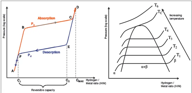
− equation II-2A common method used to characterise metal hydrides is by using a graph in which the hydrogen equilibrium pressure is plotted versus the hydrogen to metal ratio at a constant temperature. These curves are commonly called the pressure composition isotherms and give the equilibrium pressure-composition at a given temperature.
Hydrogen / Metal ratio (H/M) P re ss ur e (l og s ca le ) T1 TC T4 T3 T2 T6 Increasing temperature + Hydrogen / Metal ratio (H/M) P re ss ur e (l og s ca le ) Desorption Absorption C1 C2 CMAX Reversible capacity A B C D E F Pa Pd Hydrogen / Metal ratio (H/M) P re ss ur e (l og s ca le ) T1 TC T4 T3 T2 T6 Increasing temperature + Hydrogen / Metal ratio (H/M) P re ss ur e (l og s ca le ) Desorption Absorption C1 C2 CMAX Reversible capacity A B C D E F Hydrogen / Metal ratio (H/M) P re ss ur e (l og s ca le ) T1 TC T4 T3 T2 T6 Increasing temperature + Hydrogen / Metal ratio (H/M) P re ss ur e (l og s ca le ) T1 TC T4 T3 T2 T6 Increasing temperature + Hydrogen / Metal ratio (H/M) P re ss ur e (l og s ca le ) Desorption Absorption C1 C2 CMAX Reversible capacity A B C D E F Hydrogen / Metal ratio (H/M) P re ss ur e (l og s ca le ) Desorption Absorption C1 C2 CMAX Reversible capacity A B C D E F Pa Pd
Figure II-8 Schematic isothermal pressure composition hysteresis loop and the influence of the temperature on the isotherms
In the figure above, P is the hydrogen equivalent pressure, H/M the hydrogen to metal ratio, α represents the metal phase (with interstitial hydrogen), β the hydride phase, Pa the hydrogen absorption pressure and Pd the hydrogen desorption pressure.
At temperatures below the critical temperature, TC, two phase regions exist between the solid solution (α phase) and the hydride (β phase). A two-phase region, as indicated in the figure above on the right hand side, separates these two regions. At a temperature above the critical temperature this two-phase region no longer exists. The PC isotherm delineate three distinct sections:
1. Initially the isotherm ascends fast (section A-B) as hydrogen enters the metal lattice and occupies interstitial positions: solid solution of hydrogen in the metal lattice. By convention, this metal/hydrogen compound is called the α-phase. The hydrogen is then dissolved interstitially [15]. Sievert’s law can often be applied in this particular region:
P . K
MH= s equation II-3
When the hydrogen content in the metal increases, the hydrogen atom interact, via the elastic strains introduced in the metal lattice, and the pressure/composition behaviour departs from
ideality. This is reflected by a decrease in the slope of the isotherm compared to the ideal Sievert’s law behaviour. There is however a limit in the amount of hydrogen the α-phase can store.
2. Once the α phase is saturated, a new phase, the hydride phase (β phase), starts to form. The saturation level in the α phase is quite low. There is a discontinuity in the amount of hydrogen that the metal can store: the maximum hydrogen solubility in the α phase is C1 which is significantly lower than the minimum concentration (C2) which can be stored in the β phase : typically,
( )
MH 0.11
C whereas
( )
M 1 H2
C . The plateau region (B-C) in the PCT curve corresponds to the coexistence of the α and β phases. As more hydrogen enters the metal, the fraction of the α-phase decreases whereas the fraction of the β-phase increases. According to Gibb’s phase rule, the equilibrium pressure ideally remains constant in the two-phase region, but most practical hydriding metals do not show perfectly flat plateaus or zero hysteresis. Nevertheless, with constant temperature, the equilibrium pressure should ideally remain constant but this equilibrium pressure is highly temperature dependent (right hand side of the Figure II-8).
3. At the end of the plateau, the entire metal/hydrogen alloy consists of only the β phase. To force more hydrogen into the alloy requires increasing the external gas pressure, which is represented by the rapid increase of the equilibrium pressure in the C-D region of the PCT curve. This is an indication of a solid solution of hydrogen in the β phase.
The hydrogen absorption and desorption reactions can be modelled thanks to the shrinking core model [16], illustrated in the Figure II-9 below:
Alloy particle Partly hydrogenated particle Fully hydrogenated particle Hydride ( ) Alloy ( ) Fully hydrogenated particle Alloy particle Partly discharged particle Hydride ( ) Alloy ( ) Charge Hydrogen absorption Discharge Hydrogen desorption Alloy particle Partly hydrogenated particle Fully hydrogenated particle Hydride ( ) Alloy ( ) Alloy particle Partly hydrogenated particle Fully hydrogenated particle Alloy particle Partly hydrogenated particle Fully hydrogenated particle Hydride ( ) Alloy ( ) Fully hydrogenated particle Alloy particle Partly discharged particle Hydride ( ) Alloy ( ) Charge Hydrogen absorption Charge Hydrogen absorption Discharge Hydrogen desorption Discharge Hydrogen desorption
Figure II-9 Hydrogen absorption and desorption in a spherical shaped hydrogen storage alloy assuming the shrinking core model [16]
In practice, the reversible hydrogen storage capacity equals the length of the plateau C2-C1. The reversible capacity is defined as the plateau width, which can be considerably less than the maximum storage capacity Cmax. Depending on the available pressure and temperature ranges, the engineering capacity is usually somewhere between the reversible hydrogen storage capacity and the maximum storage capacity.
The storage capacity can either be listed in the atomic ratio (H/M), or as a weight percent. It is also possible to express the capacity in volumetric terms which is the number of hydrogen atoms per unit volume.
The Van’t Hoff plot can also be frequently used in order to compare hydrides of varying thermal stability, and is based upon the effect of the temperature on the PCT isotherm and allows the calculation of the change in the standard enthalpy and entropy. An illustration on how the Van’t Hoff plot is made is shown in the Figure II-10 below:
Hydrogen / Metal ratio (H/M) P re ss ur e (lo g sc al e) T1 Tc T4 T3 T2 T6 Increasing temperature + 1/T (K-1) P re ss ur e (lo g sc al e) T1 Tc T4 T3 T2 R H slope=∆ 0 R S ercept int =∆0 Hydrogen / Metal ratio (H/M) P re ss ur e (lo g sc al e) T1 Tc T4 T3 T2 T6 Increasing temperature + 1/T (K-1) P re ss ur e (lo g sc al e) T1 Tc T4 T3 T2 R H slope=∆ 0 R S ercept int =∆0
Figure II-10 Temperature effect on the isotherms and Van’t Hoff plot for a hydrogen storage alloy
The standard free energy change in the reaction of hydrogen absorption/desorption is given by the equation ) ln( . 2 0 RT PH G = ∆ equation II-4
where pH2 is the equilibrium hydrogen pressure. The correlation between the free energy, the enthalpy and the entropy is well known through the equation
0 0 0 H T S
G =∆ − ∆
∆ equation II-5
and by combining the three equations we can find the Van’t Hoff reaction:
R 0 S 0 ) 2 ln(PH =∆RTH −∆ equation II-6
The entropy and the enthalpy of the hydriding reaction can be found from the Van’t Hoff plot by plotting the logarithm of the plateau pressure versus the inverse of the temperature for different temperatures. The entropy change and the enthalpy change can be found by linear regression:
intercept = ∆RS0 and slope = R∆H0 equation II-7
It should be noted that the free entropy change and the free enthalpy change are both negative as the hydriding process is exothermic and requires cooling, whereas the dehydriding process is endothermic and requires heating.
2.4.2 Different types of metal hydrides
The temperature and pressure of the hydriding and dehydriding reactions depend on the specific composition of the hydride, but generally, metal hydride systems for hydrogen storage can be classified as either high (~300°C) or low (< 150°C) temperature, depending on their operating temperature at low pressure (1 to 10 bars). Hydrogen can be stored in the form of a hydride at higher densities than by simple compression, but hydrides are very susceptible to contamination, so the hydrogen supplied must be very pure.
In order to achieve desirable Pressure-Composition-Temperature (PCT) properties it is necessary to combine some strongly hydriding elements (denoted as ‘A’) with elements that have weaker hydriding properties (denoted as ‘B’). There are several types of intermetallic compounds containing different amounts of A and B elements, compounds that are more like solid solutions, and hydride complexes that are formed with transition metals. These different “hydride-families” are shown below.
The figure below shows the Van’t Hoff lines for various AB5 intermetallic compounds. The most important example of AB5 class alloys is LaNi5. This family has an extraordinary versatility because
many different elemental species can be substituted into A and B lattice sites. Classical examples of substitutes for A are Mm [17], Ca, Y, Zr. and for B Al, Mn, Si, Zn, Cr, Fe, Cu, and Co. A partial replacement of the A and B components significantly changes the alloy macrostructure. For example, replacing some of the Ni in LaNi5 alloy with Co and Fe decreases the volume expansion upon
hydriding, decreases the corrosion rate, and improves the cycle lifetime of the hydride.
The PCT properties of various AB5 alloys are shown in Figure II-11. The broad range of PCT
versatility and modifiability is evident. With the AB5’s the hysteresis is usually quite low, except for MmNi5 [18]. One distinct advantage of AB5 alloys is that they do not form protective oxide layers and
have thus a good tolerance against small amounts of O2and H2O impurities in H2.
Figure II-11 Van’t Hoff lines for various AB5 hydrides [18]
The hydrogen capacity of AB5hydrides is unfortunately low. A maximum capacity of 1.9 wt% can be achieved with LaCo5 and Ca0.7Mm0.3Ni5 with a nominal amount of about 1 wt% [19]. The reversible capacity of 1.28 wt% can be achieved with LaNi5, with the nominal amount being about 0.7 – 1 wt% [18,19]. Also the cost of AB5alloys is quite high [19].
Like the AB5s, the AB2 intermetallic alloys represent a large and versatile group with favourable PCT properties near the ambient temperature. The A elements are usually Ti, Zr, Hf, TH, or a lanthanide (atomic number 57 – 71). The B elements can be a variety of transition and non-transition metals, such as V, Cr, Mn, and Fe. A wide variety of substitutes provide a high degree of tuning the PCT and other properties. The hydrogen capacities of AB2 alloys are comparable to AB5 on a reversible basis but generally have higher maximum capacities, especially, when larger pressures and temperatures are available. The maximum capacities are usually in the range of 1.5 – 2 wt% [18,20] and with TiCr1.2V0.8 even 3.4 wt% can be achieved [19].
The intermetallic AB alloys are mainly TiFe-based. They tend to have two plateaus, the upper of which not necessarily very stable, and the hysteresis is also quite large. PCT properties can be modified by partial substitution of Fe by Mn or Ni. Oxide films are easily formed on TiFe-based alloys. This decreases the sensitivity to impurities in hydrogen.
The maximum hydrogen capacities of AB alloys vary from less than 1 to 2 wt%. The two interesting alloys, TiFe and TiFe0.85Mn0.15, have the maximum capacity of about 1.9 wt% and a reversible capacity of 1.5 wt%. The major reasons why AB alloys are not used commercially are the instability of the upper plateau and the sensitiveness for impurities [18,19].
![Figure II-5 Comparison of storage efficiencies as a function of storage envelope [9]](https://thumb-eu.123doks.com/thumbv2/123doknet/2972632.82739/26.892.135.804.445.687/figure-ii-comparison-storage-efficiencies-function-storage-envelope.webp)
![Figure II-9 Hydrogen absorption and desorption in a spherical shaped hydrogen storage alloy assuming the shrinking core model [16]](https://thumb-eu.123doks.com/thumbv2/123doknet/2972632.82739/31.892.90.762.567.812/figure-hydrogen-absorption-desorption-spherical-hydrogen-assuming-shrinking.webp)
![Figure II-13 Model illustrating adsorption processes on a heterogeneous porous surface [33]](https://thumb-eu.123doks.com/thumbv2/123doknet/2972632.82739/37.892.224.639.550.800/figure-model-illustrating-adsorption-processes-heterogeneous-porous-surface.webp)
![Figure II-20 Schematic representation of the arrangement of platelets in a catalytically grown graphite nanofibre [40]](https://thumb-eu.123doks.com/thumbv2/123doknet/2972632.82739/46.892.237.707.143.416/figure-schematic-representation-arrangement-platelets-catalytically-graphite-nanofibre.webp)
![Figure II-26 Schematic diagram of the electric arc discharge process [49]](https://thumb-eu.123doks.com/thumbv2/123doknet/2972632.82739/50.892.280.678.800.1053/figure-ii-schematic-diagram-electric-arc-discharge-process.webp)
![Figure II-36 Excess adsorption isotherms of CH 4 and H 2 on AX-21 activated carbons [84]](https://thumb-eu.123doks.com/thumbv2/123doknet/2972632.82739/67.892.206.673.340.637/figure-ii-excess-adsorption-isotherms-ch-activated-carbons.webp)
![Figure II-37 Comparison of the H 2 storage density at –196°C as a function of pressure [76]](https://thumb-eu.123doks.com/thumbv2/123doknet/2972632.82739/68.892.236.744.226.526/figure-ii-comparison-h-storage-density-function-pressure.webp)
![Figure II-38 Schematic representation of the structure of a graphite nanofibre and details of the hydrogen adsorption process [42]](https://thumb-eu.123doks.com/thumbv2/123doknet/2972632.82739/69.892.155.698.867.1095/figure-schematic-representation-structure-graphite-nanofibre-hydrogen-adsorption.webp)