HAL Id: hal-01122725
https://hal.archives-ouvertes.fr/hal-01122725
Submitted on 29 Apr 2015
HAL is a multi-disciplinary open access
archive for the deposit and dissemination of
sci-entific research documents, whether they are
pub-lished or not. The documents may come from
teaching and research institutions in France or
abroad, or from public or private research centers.
L’archive ouverte pluridisciplinaire HAL, est
destinée au dépôt et à la diffusion de documents
scientifiques de niveau recherche, publiés ou non,
émanant des établissements d’enseignement et de
recherche français ou étrangers, des laboratoires
publics ou privés.
MARTE to PiSDF transformation for data-intensive
applications analysis
Manel Ammar, Mouna Baklouti, Maxime Pelcat, Karol Desnos, Mohammed
Abid
To cite this version:
Manel Ammar, Mouna Baklouti, Maxime Pelcat, Karol Desnos, Mohammed Abid. MARTE to PiSDF
transformation for data-intensive applications analysis. Design & Architectures for Signal & Image
Processing (DASIP), Oct 2014, Madrid, Spain. �hal-01122725�
MARTE to
ΠSDF transformation for data-intensive
applications analysis
Manel Ammar and Mouna Baklouti
CES Laboratory
National Engineering School of Sfax Sfax, Tunisia
Email: manel.ammar@ceslab.org
Maxime Pelcat and Karol Desnos
IETR, INSA Rennes CNRS UMR 6164, UEB
Rennes, France
Email: mpelcat, kdesnos@insa-rennes.fr
Mohamed Abid
CES Laboratory
National Engineering School of Sfax Sfax, Tunisia
Abstract—This paper proposes and validates a new method-ology to facilitate the analysis of modern data-intensive ap-plications. A major part of handling the processing needs of these applications consists in using the appropriate Model-of-Computation (MoC) which guarantees accurate performance estimations. Our methodology introduces one major contribution that facilitates the analysis step in the co-design flow. It is based on an intermediate level of abstraction implementing the Parameterized and Interfaced Synchronous Dataflow (ΠSDF) semantics. In the proposed methodology, a system designer models the embedded system using the standardised Modeling and Analysis of Real-Time and Embedded Systems (MARTE) profile. High-level models are then refined towards intermediate level models by following the Model-Driven Engineering (MDE) transformation paradigm. The model-to-model transformation permitting to reach the ΠSDF level starting from a MARTE-compliant model is detailed and validated in this paper. It is shown to facilitate system analysis.
Keywords—Co-Design, MARTE, ΠSDF, MDE, SoC
I. INTRODUCTION
Data-intensive processing is an extensive domain of ap-plications which denotes the manipulation of a considerable amount of data and the execution of numerous complex computations [1]. A data-intensive application is an application that explores, inquires, examines, data and in general deals with very large scale data streams. A high complexity of data structures, important application parallelism, large data storage and strong computational requirements are common characteristics of data-intensive applications.
Current data intensive processing applications are various including both multimedia and high complexity numerical and scientific applications. Typical high performance multimedia applications are image processing, video processing and detec-tion systems (radar, sonar). They are designed to manipulate all type of signals (signals of interest can include sound, images, time-varying measurement values and sensor data) and they belong to the multidimensional signal processing area.
At the present time, embedded systems are commonly dedicated to data intensive processing applications where huge amounts of data are handled in a regular way by means of repetitive computations. These applications deal with inten-sive or masinten-sive parallelism. Indeed, parallel applications can implement two levels of parallelism: data parallelism and task parallelism. High-level analysis of data-intensive applications
becomes a complex task necessitating a refinement step toward low levels of abstraction specifying both computation and communication costs in the system. Accurate performance numbers can be reached at the cost of very detailed modeling. On the other hand, a moderate effort for modeling leads to a high-level evaluation task, but the accuracy is lost.
In this paper, we propose a new approach that takes advan-tage of Model-Driven Engineering (MDE) [2] foundations and Modeling and Analysis of Real-Time and Embedded Systems (MARTE) [3] profile. We define a transformation to a new level of abstraction that alleviates the exploration and analysis tasks of real-time data-intensive processing applications. This level is based on a novel extension of the famous Synchronous Data Flow (SDF) [4] Model-of-Computation (MoC), the Pa-rameterized and Interfaced Synchronous Dataflow (ΠSDF) [5] model. ΠSDF facilitates the specification, and especially the analysis of data-intensive applications [5] as it gathers a lot of features including hierarchy, configurability and dynamism. This MoC introduces analysis techniques facilitating the design space exploration task. The proposed methodology necessitates the high-level specification of the parts needed to build the embedded system. Once the user defines the application algo-rithm on the one hand, and the HW architecture on the other hand using the MARTE profile, a ΠSDF-compliant model of the application is generated. Then, a high-level analysis of the data-parallel application is performed using the PREESM [6] rapid prototyping tool.
Our primary goal is to analyze the modeled application taking as intermediate representation a ΠSDF graph. Two Model-to-model transformations are then developed to convert Unified Modeling Language-based (UML) [7] models into a ΠSDF graph. The conversion of a UML modeled parallel application to ΠSDF is made possible by intermediate meta-models that enrich the specified system for eventual analysis. This paper details the implementation of these transformations, denoting some transformation rules and describing involved meta-models.
This paper is structured into five sections. The MARTE and the ΠSDF MoCs which present the main concepts of our flow, and some related works dedicated to modern application modeling and analysis are highlighted in Section II. Section III details our proposed methodology for data-intensive ap-plications analysis. The MARTE to ΠSDF transformation is detailed in Section IV. Finally, a case study is described in Section V as a validation of our approach.
II. CONTEXT
This section introduces the basic concepts on which our flow relies. We first present the MARTE profile, which allows the co-specification of the embedded system. Then, we introduce the ΠSDF MoC that offers mechanisms used for application analysis. Finally, we briefly discuss some approaches for data-intensive application analysis.
A. MARTE profile
The standardized MARTE profile is structured around two central concerns: modeling the characteristics of embedded systems and annotating the models to support analysis of the system features. These concerns can be achieved thanks to the presence of numerous stereotypes that can be used to annotate the UML models for further analysis. Defining accurate semantics for time and Hw/Sw resource modeling and supporting real-time and embedded systems co-design flows are the major goals of the MARTE profile. These two goals can be achieved using the MDE foundations when defining embedded systems design flows. In one hand, MDE facilitates automatic transformations from one abstraction level to a lower one, for simulation or implementation purposes. In the other hand, it promotes the integration of different tools thanks to the transformation techniques. As a result, analysis tools, verification tools and modeling tools can be coupled in one co-design flow.
B. ΠSDF graph
Recently, several MoCs have been suggested offering high-level design. Dataflow Process Networks (DPN) [8] offer capabilities for describing data-intensive applications for con-current implementation on parallel hardware. Applications are composed of a set of tasks that need to be executed while consuming and producing data. Being a particular case of Kahn Process Networks (KPN) [8], DPN use a directed graph to describe the application’s algorithm. Numerous extensions of DPN have emerged to model different range of applications. SDF is the most known DPN MoC in which nodes can be scheduled statically onto single or parallel processors. Other dataflow models were introduced such as the Cyclo-Static Dataflow (CSDF) [9] and the multidimensional SDF [10]. Each MoC adds capabilities to the SDF model to increase its expressivity. Since parameterization and configuration have emerged as important characteristics of modern applications, an extended version of SDF has been defined to support this evolution: the Parameterized SDF (PSDF) model [11]. Actors in PSDF are dynamically reconfigurable and hierarchical. Each actor relies on a set of parameters to control its functionality and its data flow behavior.
Tasks of signal processing applications are broken into sub-tasks in recent programming practices favoring hierarchy modeling of complex computations. A hierarchical extension of the SDF model, the Interface-Based SDF (IBSDF) MoC [12], promotes sub-graph composition by adding interface elements aiming to separate levels of hierarchy.
The ΠSDF MoC extends the PSDF and IBSDF models to accommodate a broader range of applications by enforcing parameterization, hierarchy and configuration [5]. A ΠSDF graph G=(A,F,I,Π,∆) is composed of:
• A: A set of actors
• F: A set of First In, First Out data queues (FIFOs) • I: A set of hierarchical interfaces
• Π: A set of parameters
• ∆: A set of parameters dependencies
The ΠSDF MoC supports four important characteristics which are:
• Parameterization: parameterization relies on param-eters which are vertices of the graph G. A parameter value is associated to each parameter to configure elements of the graph. The allocation of parameter values to all parameters in Π represents a configuration of G.
• Hierarchy: enforcing the compositionality by taking interface-based hierarchy mechanism as a foundation for component tasks modeling can be a good practice when facing complex computations.
• Reconfiguration: reconfiguration in the ΠSDF se-mantics means changing a parameter value at run time or at compile time. Reducing the frequency of pa-rameter value modifications is facilitated through two types of parameters in the ΠSDF model: configurable parameters and locally static parameters.
• Analysis: ΠSDF introduces semantics to express application’s dynamism. Such dynamism is driven by parameters which can be of two types: dynamic or static. These two degrees of dynamism necessitate a two-step analysis of the graph (compile time analysis and runtime analysis) in order to check application properties such as memory boundedness, consistency and deadlock freeness, which are critical information when exploring the design-space of complex real-time systems.
SDF MoC can serve two different purposes: specification and analysis. There has been many researches on the problem of application analysis based on the SDF MoC. Most of these efforts focus on throughput analysis [13], [14] and resource requirements (memory usage) [15], [16] of DSP and multi-media applications. A number of frameworks have attempted to propose graphical formalisms to model and analyze data-intensive signal processing applications specified using the SDF MoC. Some examples are Ptolemy II [17], PREESM [18] and SDF3 [19]. These frameworks are open-source and support experimentation with actor-oriented design. Ptolemy II provides simulation of signal processing applications specified using many MoCs. SDF3 supports SDF, CSDF and scenario-aware dataflow (SADF) [20] models. It allows transformation and analysis of SDF graphs using different algorithms and targeting MPSoC architectures, the feature that differentiates SDF3 from Ptolemy II. PREESM provides a hierarchical actor-based description of the application based on ΠSDF and IBSDF MoCs. It includes several algorithms offering automatic mapping and scheduling. In addition, the application and architecture code files can be generated automatically for heterogeneous multicore embedded systems.
C. Design space exploration approaches
Several UML-based design frameworks have been sug-gested targeting the design space exploration problem. The MODES framework presented in [21] uses the UML class, composite structure and sequence diagrams enriched with the MARTE stereotypes for the functional specification of the embedded application. It then automatically generates a control and data flow internal representation conforming to a number of meta-models. Additional meta-models and transformations are defined to perform the DSE phase. MODES is based on a flow of transformations between different tools. In fact, while the H-SPEX and the SPEU tools are used for the DSE and estimation tasks, the UPPAAL model checking tool is used to validate the functional and temporal properties of the specification, taking as input a network of timed automata. In the Koski flow [22], two steps are needed to ensure architecture exploration. First, a static analysis of the application model is done. Then iterative simulations take place in order to explore the architecture. This flow relies mainly on UML to model application, architecture and the association between them.
COMPLEX [23] and MADES [24] are EU FP7 projects aiming to use high-level models for the design of real-time and embedded systems. The COMPLEX framework mixes system-level power optimization and rapid prototyping techniques in a platform-based design flow. Subsets of the MARTE profile are used to specify the system and UML use-cases are modeled to generate systems stimuli. While executable specifications are generated automatically from UML models allowing sep-arate hardware and software estimation, the mapping is done manually and provided as a design entry. Several system-level estimation tools are combined together to facilitate power and execution time evaluation. The MADES project proposes a methodology that combines MARTE and SysML in a design flow targeting embedded avionics systems. This flow focuses on modeling, verification and hardware and software genera-tion steps. However, the design space exploragenera-tion step is not supported in this framework. In fact, the main focus of this framework is the specification and how the user can combine different profiles to give a complete view of the system.
III. OVERVIEW OF THE PROPOSEDDSEFLOW
Our proposed multi-level design space exploration methodology will be outlined in this section. The implemen-tation of model transformations and the integration of a rapid prototyping tool will be also highlighted.
A. A multi-level DSE flow
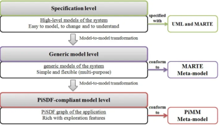
Our approach for the embedded systems design automation, highlighted in Figure 1, can be divided into three levels: the specification level, the generic model level and the ΠSDF-compliant model level.
1) The specification level: The first level, specification level, presents the entry point of our flow. Models of the architecture, the data-parallel application and the Hw/Sw IP deployment are described using diagrams of the UML lan-guage and notations of the MARTE profile. These models are specified by a user with UML modeling tools such as Papyrus [25]. The system properties, including application and architecture properties (execution time, frequency, etc.),
Fig. 1. The proposed multi-level flow
are specified in the same UML model using the appropriate stereotypes. Five MARTE packages are used to annotate a given UML model:
• Hardware Resource Modeling (HRM): used to specify the detailed platform architecture elements
• Software Resource Modeling (SRM): allows to anno-tate tasks of the application and specify the execution time value of each modeled task
• Repetitive Structure Modeling (RSM): used to express the repetitive concepts of the system including the data-parallel computations and the massively parallel processing elements
• Generic Component Model (GCM): used to specify the nature of flow-oriented communication paradigm between SoC components. It is a general model pack-age that includes interaction ports, flow ports, and message ports
• Non-Functional Properties (NFP): supports the mod-eling of the systems performance requirements and constraints like time, energy, area,etc.
Modeling a given embedded system is carried out based on three UML diagrams: the class diagram, the composite structure diagram and the deployment diagram. The class diagram illustrates the structure of the embedded system by demonstrating the systems components including hardware and software components (presented using classes) and their characteristics (attributes and operations of the classes). The internal structure of each hierarchical component is specified using the composite structure diagram. These two diagrams cover effectively the modeling of the static structure of an embedded system in a co-design approach. Elementary com-ponents of the hierarchical component interact with each other using ports and connectors. In order to specify the corre-sponding implementation of a given elementary component, an UML mechanism is well defined. This mechanism, named Deployment, is a powerful tool that allocates IPs on hardware and software components. Our flow adopts a Platform-Based Design approach that benefits from an IP library containing
IPs of the architecture and IPs of the application. For this reason, the structure of the data-flow model of the application is described using the composite structure diagram and the behavior of the elementary tasks is embedded in the software IPs. Similarly, the structure of the architecture is defined in the composite structure diagram of the architecture and the source code of hardware components is provided in the IP library. This adopted modeling methodology simplifies the design entries as much as possible without losing precision in the analysis phase or in the code generation process. In fact, models of the architecture and application define the main components of the system in a high-level graphical manner giving a better understanding of the system even for a non-expert user. In addition, low-level behavioral information of the architecture and the application can be exploited by the analysis tool to generate precise estimation results. These IPs are also used to generate the entire system from UML models. While the structure of the application and the architecture can be directly concluded from class and composite structure diagrams, the behavior inside each code file describing each component can be extracted from the provided IP library.
2) The generic model level: When developing our ap-proach, two possibilities were proposed. The first was to generate a ΠSDF model directly from the UML models of the application. This alternative is certainly a time-consuming task. It necessitates intensive programming. In fact, UML diagrams are rich with UML concepts and MARTE notations. This fact makes the UML model browsing difficult especially when the application contains intensive computations. A second alternative was then proposed: defining an intermediate level that captures necessary parts of the system and is generic enough to facilitate exploration and code generation. This level can be identified as mandatory transit in each transformation targeting either analysis or code generation.
3) The ΠSDF-compliant model level: While high-level models of the system in the first level are easy to specify, to change and to understand, the ΠSDF graph of the application, in the third level, is rich with exploration features. This graph is used for application analysis because besides its exploration features it:
• Adequately fits with the targeted signal-processing domain
• Supports the specification and analysis of massively-parallel data-flows because it is hierarchic
• Facilitates the exploration of parametric architectures given that data-flows of the application can depend on static or dynamic parameters
B. Model transformations
In our framework, we use an approach in which we start from a structural application and architecture description which is then converted into a ΠSDF for analysis and performance estimation. This conversion is automatic and guided by two model-to-model transformations as shown in figure 2. The im-plementation of the transformations is driven by the definition of a set of transformation rules. Each rule specifies how one or more concepts in the source model can be converted into other concepts in the target model. In our approach, transformation
Fig. 2. Model-to-model transformations
rules are defined using the QVTO language [26], an imper-ative language for model transformation designed for writing unidirectional transformations.
1) The UML to MARTE transformation: The top level of our design flow, the specification level gives a clear and complete view of the system. However, the collection of common notions present in the MARTE profile is not precise enough to directly allow the analysis of the system model. This fact justifies the integration of another level that facilitates the analysis process. Since the MARTE meta-model captures the structure of the embedded system and keeps characteristics of the hardware and software components (specified using stereotypes), it has been introduced in our framework to be a base in the intermediate level between the system specification and the ΠSDF model generation. This level, named the generic model level, is totally based on the open-source MARTE meta-model provided with the source code of Papyrus. As part of our efforts, a model-to-model transformation has been created to generate generic models of the application and architecture that are conforming to the MARTE meta-model.
2) The MARTE to ΠSDF transformation: Starting from a generic model of the application, a second model-to-model transformation has been defined to generate a ΠSDF-compliant model. This transformation will be detailed in the next section. The creation of the ΠSDF-compliant model level is based on an Ecore version of the PiMM model. ΠSDF meta-model allows a description of the data-parallel application at the ΠSDF-compliant model level, the third abstraction level in our flow. The ΠSDF-compliant model and the generic model of the architecture, will be provided as design entries to the PREESM tool for analysis and performance estimation. The results obtained from the analyses enable to generate files of the adequate models of the application and the architecture. C. Mapping, scheduling and performance estimation using PREESM
PREESM is an open-source framework for the rapid proto-typing and code generation of multi-core DSP-based systems. The inputs to this rapid prototyping framework are:
• Models of the application: specified using the IBSDF MoC or the ΠSDF MoC.
• Models of the architecture: specified using the System-Level Architecture Model (S-LAM) [27] of PREESM
or the MARTE profile
• Scenario: references the application and the archi-tecture, encapsulates several constraints including scheduling and simulation constraints and contains the execution time values of each actor of the ΠSDF graph. These values can be specified in the UML models and directly transmitted to the scenario or imported from Excel sheets.
• Workflow: used to accelerate the rapid prototyping process by specifying transformations necessary to analyze, simulate or generate executable code. Several mapping/scheduling can be carried out in PREESM. As result of the schedulability analysis process, performance values can be examined including the worst case execution time and the percentage of necessary load and memory. These provided results enable design space exploration.
IV. MARTETOΠSDFMODEL TRANSFORMATION
It is the objective of this paper to focus on the MARTE to ΠSDF model transformation. Source and target meta-models of the transformation will be described first. Then, some transformation rules will be mentioned.
A. The source meta-model: MARTE
The first transformation, UML to MARTE transformation, generates a model that conforms to the MARTE meta-model. The MARTE meta-model contains numerous meta-classes encapsulated in different packages. The generated MARTE model contains basically elements from the GCM and RSM packages. Meta-classes from the GCM and the RSM packages are used as input for the MARTE to ΠSDF transformation. The design entries of our flow are composite structure diagrams of the application and architecture. The first transformation that takes UML structured diagrams of a given model and generates a GCM-compliant model can preserve the hierar-chical structure of a model without losing any detail and without being tied to specific execution semantics. In fact, the hierarchical structure of a model is preserved thanks to the GCM model from the MARTE meta-model because this model is an abstraction of the UML structured classes.
For this reason, a GCM-based model of an embedded sys-tem can be regarded as a generic model that contains enough details for further transformations. A GCM-based model is composed of a set of Structured Component. A Structured Component encapsulates Assembly Parts, Interaction Ports and Connectors. Interaction Ports are either Flow Ports or Message Ports. Since we focus on intensive data-flow computations, only Flow Ports will be used in the specification level. Con-nectors have connector Ends that can be Interaction Ports or Assembly Parts. Connectors between two Assembly Parts are Assembly Connectors. The stereotypes from the RSM package are present in the MARTE meta-model as meta-classes. While these stereotypes model the multiplicities of repeated tasks and ports in the UML models, they specify the shape of an AssemblyPart or a FlowPort in the MARTE meta-model. Stereotypes specifying complex interconnection topologies, es-pecially the tiler and the interRepetition stereotypes, figure out in the MARTE meta-model to specify the kind of Connectors
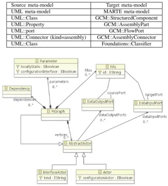
TABLE I. SOMEUMLTOMARTETRANSFORMATION RULES
Source meta-model Target meta-model UML meta-model MARTE meta-model UML::Class GCM::StructuredComponent UML::Property GCM::AssemblyPart UML::port GCM::FlowPort UML::Connector (kind=assembly) GCM::AssemblyConnector UML::Class Foundations::Classifier
Fig. 3. ΠSDF meta-model
and AssemblyConnectors meta-classes. Being the output of the first transformation, the generic model of the application is obtained using transformation rules. These transformations map elements from the UML meta-model into elements from the MARTE meta-model. Table I summarizes some of these rules.
B. The target meta-model: PiMM
The PiMM meta-model reflects a subset of the semantics of the ΠSDF MoC. Figure 3 depicts a portion of the ΠSDF meta-model. The highest concept present in the ΠSDF meta-model is the PiGraph meta-class representing the graph of the applica-tion or a sub-graph of a given hierarchical actor. A model that complies with the ΠSDF meta-model consists of one or more PiGraphs. A PiGraph can contain several vertices, parameters, dependencies and fifos. An AbstractActor, presenting one vertex, can be either an actor (hierarchical or elementary) or an interface, expressed via Actor and InterfaceActor meta-classes. An AbstractActor can enclose an arbitrary number of DataInputPort by means of the compositional dataInputPort relation. Moreover, the same AbstractActor can hold numerous DataOutputPort by means of the compositional dataOutputPort relation. The Expression meta-class defines the rates of data input ports and data output ports by means of the expression relation; while the Port meta-class defines the name and the kind (in/out) of the port itself.
C. Transformation rules
The MARTE to ΠSDF QVTO transformation includes numerous rules among which we will detail six rules that are representative of the global transformation.
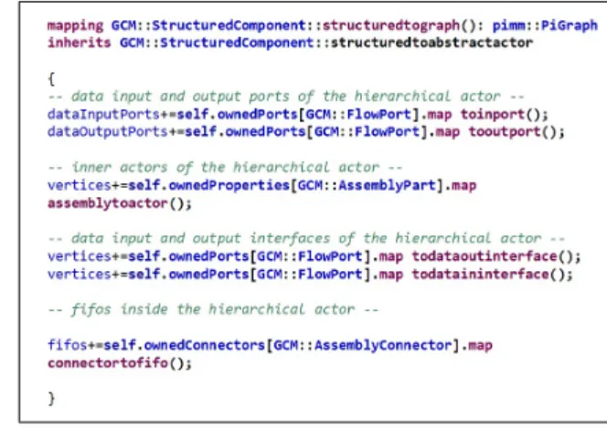
1) StructuredComponent to PiGraph: The generic model of the application, resulting from the UML to MARTE trans-formation, contains one or more StructuredComponents. A
StructuredComponent presents either a hierarchical sub-task containing a net of other sub-tasks or the main application including a set of hierarchical tasks. A generic model of a given application can be composed of one StructuredComponent denoting the main application and zero or more Structured-Components illustrating the hierarchical sub-tasks if they exist. Looking at the PiMM meta-model, the PiGraph meta-class can present either a hierarchical actor or the main ΠSDF graph of the application. In fact, the ΠSDF hierarchy, which is a top-down hierarchy, allows to compose sub-PiDSF graphs within an upper-level ΠSDF graph. While each sub-ΠSDF graph has input and output data interfaces facilitating data-exchange between the hierarchical actor and its sub-graph, the upper-level ΠSDF graph contains a net of actors communicating via data input and output ports. The first mapping in the MARTE to ΠSDF transformation allows to convert each Structured-Component in the MARTE-compliant model into a PiGraph. If the StructuredComponent specifies the main application, data input and output interfaces will be created in the PiGraph as shown in figure 4. Otherwise, the rule that creates these interfaces will be eliminated.
Fig. 4. StructuredComponent to PiGraph transfomation rule (QVTO)
2) AssemblyPart to Actor: An AssemblyPart belonging to a StructuredComponent is a sub-task that can be an elementary or a hierarchic one. Each AssemblyPart in the generic model of the application is converted into an Actor using the mapping rule of figure 5. An actor communicates with other actors in the ΠSDF graph using data input and output ports. For this reason, ports of the AssemblyConnector became ports of the Actor calling the appropriate mapping rule.
Fig. 5. AssemblyPart to Actor transfomation rule (QVTO)
3) FlowPort to Port: The FlowPort stereotype gives seman-tics to fix the direction of a given port. This characteristic is preserved in the MARTE-compliant model thanks to the UML
to MARTE transformation. Since the direction of the port is important in the definition of a ΠSDF graph, two mapping rules were defined to convert a FlowPort into a Port depending on its direction kind. A FlowPort having a direction equal to in becomes a data input port (as shown in figure 6) and a FlowPort with an out direction turns into a data output port.
Fig. 6. FlowPort to Port transfomation rule (QVTO)
4) FlowPort to Interface: FlowPorts of the StructuredCom-ponent that specifies a hierarchical sub-task are converted into data input and output interfaces.
5) AssemblyConnector to FIFO: An AssemblyConnector gathers two AssemblyParts inside the StructuredComponent. While AssemblyParts of a given StructuredComponent turn into Actors in a PiGraph, each AssemblyConnectors become a FIFO linking one source port of an actor to a target port of another actor. This mapping is guaranteed thanks to the mapping rule shown in figure 7.
Fig. 7. AssemblyConnector to FIFO transfomation rule (QVTO)
6) shapeSpecification to Expression: Each input or output port in a ΠSDF graph has a rate that presents the number of tokens produced or consumed on this port. Since the Shaped stereotype applied on ports of the UML model indicates the amount of data present in these ports, this stereotype is kept in the generic model of the application and necessary information are extracted to define the rate of each port in the ΠSDF-compliant model. It is necessary to notice that the ΠSDF MoC deals only with one-dimensional streams. For this reason, 2-D streams are embedded within a 1-D stream in our transformation (figure 8) by multiplying the input streams.
Fig. 8. shapeSpecification to Expression transfomation rule (QVTO)
V. CASE STUDY: SOBEL FILTER
We introduce below the Sobel filter application [28] designed with the MARTE profile as a validation of our
developed transformations. In figure 9, the Application class corresponds to the task that reads a 2-dimension image, convo-lutes the Y component of the original image with 3∗3 matrices and finally displays the resulting image. A 2-dimension image is decomposed into three arrays materialized by the ports Y, U and V. The shape of these ports is X ∗Y . It describes the shape of the corresponding data array. X and Y denote respectively the width and height of the image. The multiplicity N associ-ated with the instance of the Elementary sobel class denotes a repetition space on a task expressing data-parallelism. Each repetition of the task consumes an X ∗ (Y /N + 2) array of pixels and produces an X ∗ (Y /N + 2) array of pixels. These consumed arrays correspond to blocks of the original image. The sobel filter is applied on each block. The construction of these blocks relies on the data dependencies expressed via the Tiler stereotype. The Tiler produces blocks with 2 extra lines of pixel: the last line from the previous block and the first line of the next block. In fact, the convolution of the image with 3 ∗ 3 matrices means that the calculation of the nth line of pixels
of the produced image requires an access to the (n − 1)thand (n + 1)thlines of pixel of the original image.
Fig. 9. Model of the Sobel filter application
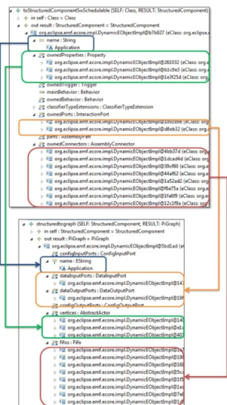
We now study the refinement of the high-level models via our implemented transformation chain. The first step consists in targeting the MARTE meta-model executing the UML to MARTE transformation. Then, the MARTE to ΠSDF model-to-model transformation is executed to generate a ΠSDF model of the application. Subsets from the trace files generated from the transformation chain are outlined in figure 10. The first trace file is the result of the UML to MARTE transformation. It outlines the generation of a StructuredComponent taking as input the Application hierarchic class. Then, this Structured-Component is transformed into a PiGraph as shown in the second file. The PiGraph incorporates actors, FIFOs and ports. Using the StructuredComponent to PiGraph transformation rule, the transformation engine creates a PiGraph having the same name as the StructuredComponent. Input and output FlowPorts of the StructuredComponent become DataInputPorts and DataOutputPorts. Finally, Connectors in the Structured-Component turn into FIFOs in the PiGraph. The Application class presents the main class of the application, for this reason, no interfaces are added to the PiGraph in the vertices field as shown in Figure 11. However, the Sobel filter class specifies a hierarchical task with a repetitive task inside; as a result,
Fig. 10. The generated trace files for the Application class
Fig. 11. The generated Application ΠSDF graph
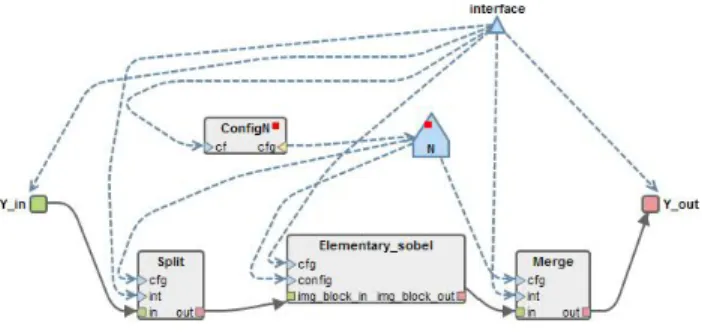
two interfaces are added to the vertices field: one data input interface and one data output interface (figure 12). Two other actors are added to the vertices list of the Sobel filter PiGraph. These actors permit respectively to split and merge the original image, the fact that insures the schedulability of the generated ΠSDF graph. The generation of these supplementary actors is due to the presence of transformation rules that verify the schedulability of each ΠSDF graph before generating the final model. These rules examine each Tiler in the generated MARTE-compliant model and decide if other actors will be built or not. The generated ΠSDF graphs include parameters and parameter dependencies. The static parameter, from the Application graph, X*Y, displays the parametric size of the original image. It is important to notice that the MARTE profile was extended to indicate whether the parametric shape of a repeated element or a port is static or dynamic. The Sobel filter graph contains a dynamic parameter, which is N. N represents the number of the repetitions of the Elementary sobel task. This repetition depends on number of processing units.For this reason, it will be defined after the analysis process.
Fig. 12. The generated Sobel filter ΠSDF graph
VI. CONCLUSION
In this paper, we have presented a model transformation for the analysis of data-intensive applications. In the proposed methodology, high-level specifications are first described by the designer using the MARTE profile. Then, the resulting models are automatically refined into another level of abstrac-tion for analysis and design space exploraabstrac-tion. The refinement technique is implemented using MDE transformation. In terms of applicability, a user models the system with an UML editor under the Eclipse framework and then executes the proposed transformation chain to generate a ΠSDF graph. An experimental validation of the UML to MARTE and MARTE to ΠSDF model-to-model transformations was detailed using a filter application. Next efforts will be concentrated on the integration of the PREESM flow in our framework. Currently, PREESM uses the S-LAM model to specify the architecture. Additional algorithms will be defined to additionally support the MARTE-based models of the architecture.
REFERENCES
[1] R.T. Kouzes, G.A. Anderson, S.T. Elbert, I. Gorton, and D.K. Gracio, “The Changing Paradigm of Data-Intensive Computing,” in IEEE Com-puter , vol.42, no.1, pp.26-34, January 2009.
[2] D. Lugato, J-M. Bruel, and I. Ober,“Model-Driven Engineering for High Performance Computing Applications,” Modeling Simulation and Optimization-Focus on Applications, Shkelzen Cakaj(Ed.), 2010. [3] Object Management Group. UML Profile for MARTE: Modeling and
Analysis of Real-Time Embedded Systems, version 1.0. Available: http://www.omg.org/spec/MARTE/1.0/PDF/.
[4] E.A. Lee and D.G. Messerschmitt, “Synchronous data flow,” Proceedings of the IEEE, vol.75, no.9, pp.1235-1245, September 1987.
[5] K. Desnos, M. Pelcat, J.-F. Nezan, S. Bhattacharyya and S. Aridh, “PiMM: Parameterized and Interfaced Dataflow Meta-Model for MP-SoCs Runtime Reconfiguration,” International Conference on Embedded Computer Systems: Architecture, Modeling and Simulation (SAMOS XIII), Samos, Greece, July 2013.
[6] M. Pelcat, “Rapid Prototyping and Dataflow-Based Code Generation for the 3GPP LTE eNodeB Physical Layer mapped onto Multi-Core DSPs,” PhD Thesis, INSA de Rennes, 2010.
[7] Object Management Group. Unified Modeling Language specification, version 2.1. Available: http://www.omg.org/spec/UML/2.1.2/ Infrastruc-ture/PDF.
[8] E.A. Lee and T.M. Parks, “Datafow process networks,” Proceedings of the IEEE, vol.83, no.5, pp.773799, May 1995.
[9] G. Bilsen, M. Engels, R. Lauwereins and J. Peperstraete, “Cyclo-static dataflow,” IEEE Transactions on Signal Processing, vol.44, no.2, pp.397408, february 1996.
[10] P. Murthy and E. Lee, “Multidimensional synchronous dataflow,” IEEE Transactions on Signal Processing, vol.50, no.8, pp.20642079, aug 2002.
[11] B. Bhattacharya and S. Bhattacharyya, “Parameterized dataflow mod-eling for DSP systems,” IEEE Transactions on Signal Processing, 2001. [12] J. Piat, S. Bhattacharyya, and M. Raulet, “Interface-based hierarchy for
synchronous data-flow graphs,” In SiPS Proceedings, 2009.
[13] A.-H. Ghamarian, M. C W Geilen, S. Stuijk, T. Basten, A. J M Moonen, M.J.G. Bekooij, B.D. Theelen, M.R. Mousavi, “Throughput Analysis of Synchronous Data Flow Graphs,” Sixth International Conference on Application of Concurrency to System Design, ACSD 2006, pp.25-36, June 2006
[14] S. Stuijk, M. Geilen, T. Basten, “Throughput-Buffering Trade-Off Exploration for Cyclo-Static and Synchronous Dataflow Graphs,” IEEE Transactions on Computers, vol.57, no.10, pp.1331-1345, October 2008. [15] Yang Yang, M. Geilen, T. Basten, S. Stuijk, H. Corporaal, “Exploring trade-offs between performance and resource requirements for syn-chronous dataflow graphs,” IEEE/ACM/IFIP 7th Workshop on Embedded Systems for Real-Time Multimedia, ESTIMedia 2009, pp.96-105, Octo-ber 2009.
[16] K. Desnos, M. Pelcat, J.-F. Nezan, S. Aridhi, “Memory bounds for the distributed execution of a hierarchical Synchronous Data-Flow graph,” International Conference on Embedded Computer Systems, SAMOS 2012, pp.160-167, July 2012.
[17] J.T. Buck, S. Ha, E.A. Lee and D.G. Messerschmitt, “Ptolemy: a Framework for Simulating and Prototyping Heterogeneous Systems,” In-ternational Journal of Computer Simulation, special issue on “Simulation Software Development”, vol.4, pp.155-182, April 1994.
[18] M. Pelcat, J. Piat, M. Wipliez, S. Aridhi and J.-F. Nezan, “An Open Framework for Rapid Prototyping of Signal Processing Applications,” EURASIP Journal on Embedded Systems.
[19] S. Stuijk, “Predictable mapping of streaming applications on multipro-cessors,” Ph.D. thesis, Technische Universiteit Eindhoven, Eindhoven, The Netherlands, 2007.
[20] S. Stuijk, M. Geilen, B. Theelen, T. Basten, “Scenario-aware dataflow: Modeling, analysis and implementation of dynamic applications,” Inter-national Conference on Embedded Computer Systems, SAMOS 2011, pp.404-411, July 2011.
[21] F.A.M. do Nascimento, M.F.S. Oliveira, F.R. Wagner, “A model-driven engineering framework for embedded systems design,” Innovations in Systems and Software Engineering, vol.8, pp.19-33, Mars 2012. [22] T. Kangas, P. Kukkala, H. Orsila, E. Salminen, M. H¨annik¨ainen and
T. H¨am¨al¨ainen, “UML-based multiprocessor SoC design framework,” In ACM Trans. Embed. Comput. Syst, vol.5, pp.281-320, May 2006. [23] K. Gr¨uttner, P. A. Hartmann, K. Hylla, S. Rosinger, W. Nebel, F.
Herrera, ... & R. Valencia, “The COMPLEX reference framework for HW/SW co-design and power management supporting platform-based design-space exploration,” Microprocessors and Microsystems, vol.37, no.8, pp.966-980, 2013.
[24] I.-R. Quadri, E. Brosse, I. Gray, N. Matragkas, L.S. Indrusiak, M. Rossi, A. Bagnato, A. Sadovykh, “MADES FP7 EU project: Effective high-level SysML/MARTE methodology for real-time and embedded avionics sys-tems,” 7th International Workshop on Reconfigurable Communication-centric Systems-on-Chip, ReCoSoC 2012, pp.1-8, July 2012.
[25] Papyrus, http://www.eclipse.org/papyrus/.
[26] P. Guduric, A. Puder, R. Todtenhofer, “A Comparison between Rela-tional and OperaRela-tional QVT Mappings,” In the 6th InternaRela-tional Confer-ence on Information Technology: New Generations, ITNG ’09, pp.266-271, April 2009.
[27] M. Pelcat, J.-F. Nezan, J. Piat, J. Croizer, S. Aridhi,“A System-Level Architecture Model for Rapid Prototyping of Heterogeneous Multicore Embedded Systems,” DASIP Conference, 2009.
[28] I. Sobel, “An Isotropic 33 Gradient Operator, Machine Vision for ThreeDimensional Scenes,” Freeman, H., Academic Pres, NY, pp.376-379, 1990.