HAL Id: hal-02046053
https://hal.archives-ouvertes.fr/hal-02046053
Preprint submitted on 13 Mar 2019
HAL is a multi-disciplinary open access
archive for the deposit and dissemination of
sci-entific research documents, whether they are
pub-lished or not. The documents may come from
teaching and research institutions in France or
abroad, or from public or private research centers.
L’archive ouverte pluridisciplinaire HAL, est
destinée au dépôt et à la diffusion de documents
scientifiques de niveau recherche, publiés ou non,
émanant des établissements d’enseignement et de
recherche français ou étrangers, des laboratoires
publics ou privés.
Dmytro Shytyi, Luigi Iannone
To cite this version:
High availability of VNF Orchestrator
Dmytro Shytyi (SFR, Paris, France) and Luigi Iannone (Telecom Paris-Tech, Paris, France)
Abstract—Network Function Virtualization allows transformation from physical proprietary hardware to general purpose servers withvirtual services. Depending on the available resources in the network, virtual services (functions) could be placed accordingly. The special entity is required too place functions and manage resources in the network. This entity is an Orchestrator. Usage of
Orchestrator raises the problem of which action to undertake in case of orchestrator failure. The problem transforms into questions like: where to place these instances? How to manage fail overs? How many instances should be placed? The Orchestrator has risk of failure thus, to provide the high availability, this paper consider the fail over and placement problems.
Index Terms—NFV, Tacker, resiliency, nodes recovery, placement.
F
1
INTRODUCTION
I
NCREASINGdemand on different network services makes network operators and big companies to increase the number and variety of complex proprietary hardware. The combination of increasing operational costs, complex inte-gration and maintenance of such hardware is strong limi-tation of increasing services. Network function vitalization introduces the different way to architect networks. This technology aims to convert different network hardware with specific functions as a virtual services that are running on the general purpose servers (GPS), network nodes such that those services could be moved to a different locations in the network instead of needing the installation of new equip-ment. To make available the transition from the various complex proprietary hardware to easy managed software (virtual functions/services) on the GPS, Network Function Virtualization platforms as OpenStack [1] appeared.While services require to be properly managed, coor-dinated, arranged and resources require to be aggregated, problems related to automation of network, storage, per-formance and provisioning appear. Frequently automation closely relates to an orchestration (coordination of the re-sources and networks needed to set up cloud-based services, applications). Correspondingly the entity responsible for or-chestration tasks without requiring direct human interaction is defined as orchestrator.
To be able to perform orchestration tasks OpenStack includes the Tacker (Manegement and Orchestration) ser-vice [14] based on MANO framework [2]. Normally Tacker server could be responsible (supervision) for multiple Open-Stack clusters. As any component it has risk of failure and in case of Tacker instance failure further operations on NFV will be impossible to perform. Thus our goal is to provide
high availability for Tacker, that we are going to achieve with appropriate placement of Tacker servers and recovery method in case of failure.
2
RELATED
WORK
The latest related studies on controller placement performed in Software Defined Networks. The most common objective for the problem is to minimize controller-switch latency
studied by Heller et al. [3], where they presented the correla-tion between number of SDN controlers, their locacorrela-tions, and controller-to-switch latency’s. Jimenez et al. [5] performed study on controller placement in SDN with k controllers by taking into account metrics such as latency. Yao et al. [4] presents placement algorithm by taking into account capacity of SDN controller. Particularly, it has been widely studied to locate a controller close to switches. Finally, mechanisms to perform failover were studied by Obadia et al. [6]. They described and tested a greedy failover strategy for neighbor active SDN controllers to take over the control of orphan switches in SDN netowrks.
2.1 Topology Model
In terms of methodology that includes fail tolerance ap-proach and controller placement, also creation of network topology model considered in the section 5.1 to perform simulations. Related work in this area includes a list of models that were studied and helped to define our model.
Balanced tree model gave an inspiration to use structure inside domains as balanced tree. However it did not satisfy desired parameters of model as presented tree has one root node.
Dorogovtsev-Goltsev-Mendes graph [16] that starts by creating three nodes and tree edges, making a triangle, and then add one node at a time. In this model each time a node is added, an edge is chosen randomly and the node is connected via two new edges, however even with a fact that this model distribution follows Power Law, it does not consider the case when Tacker servers could reach each other through intermediate nodes (OpenStack clusters).
Margulis-Gabber-Galil model [17] satisfied clustering structure and not directly connected Tacker instances, how-ever it does not present tree-type structure of OpenStack clusters for each Tacker Server.
Caveman graph model [18] satisfied multiple domains and Tacker servers were not connected directly, however it still did not allow to obtain tree structure. There were more models analyzed that could satisfy some requirements but not all of them. Those models are Waxman graph model [19], Random Powerlaw Tree model [21], Watts-Strogatz Graph model [20].
spired from the tree model and has a feature similar to Caveman relaxed graph model [22].
2.2 Placement algorithm
The part of Tacker resiliency methodology is a placement algorithm. Popular algorithms, similar to the algorithm proposed in this paper, such as means, medioids, k-center are specializing on specific metric or properties thus have some differences. For example k-means generally is used on the euclidean space and taking into account special unknown data. These clustering algorithms are from the set of algorithms that are splitting the dataset S into several parts (1, ..N ∈ S) and try to minimize the distances d(u, c) from units u ∈ Si of the part Sito the unit c ∈ Si
Main advantages of presented in this paper algorithm is the simplicity and execution time. However as a heuristic algorithm it does not always give an optimal solution. Also the number of domains to split the dataset should be predetermined. Finally the algorithm spends redundant processing time to calculate distances between arch of the k domains and N vertexes. Since most nodes after several iterations stay in the same domains, there are unnecessary redundant computation of shortest paths. Thus the pre-sented algorithm could be improved during further work.
To cope with unknown number of domains there exist approaches that could be applied. Such approaches are sil-houette method, the elbow method [15].The Elbow method could be described as a function of the number of clusters: the final number of clusters will be the one, that does not give a much better result if another cluster is added. Another way is the Silhouette method, that provides a graphical representation of how well each object lies within its cluster. One of the most recent active field where related work appears - is the Software Defined Networks (SDN) con-troller resiliency. However, some parameters such as time constrains and frequency of operation execution/message exchange in SDN highly differs from Tacker and OpenStack clusters message exchange density. For example the SDN controller placement highly depends on optimal placement of the controller. For example OpenFlow switches ask con-troller with high frequency how to operate on new pack-ets. Density of data exchange between OpenStack clusters - Tacker server (to orchestrate, to manage vitalized ser-vices, resources) and density of packets exchanges in SDN between controller and switches (while new ”unknown” packet appears on switch) is significantly differs. Thus Tacker-OpenStack cluster communication model is less sen-sitive for close to optimal placement than SDN communica-tion model.
There exist different approaches to determine domains such as Girvan-Newman method and Louivan method. Both of them try to distinguish domains by using different techniques. However they still require modifications to pro-vide the center of domains. The Girvan-Newman method [10] focuses on the edges that are less central, those that are between domains. Instead of adding the strongest edges to empty vertex set, they are constructed by progressively removing edges from the original graph. Where edge e ∈ E betweenness is defined as the number of shortest path
measure of influence of a node over the flow of information between the nodes. However it does not give proper results as it determines some of nodes from different physical locations (different domains) as those that should be carried by the same Tacker server.
Another popular algorithm is based on Louvain method [11]. It is divided in two phases that are repeated iteratively. First, a different community is assigned to each node of the network. So, in this initial partition there are as many com-munities as there are nodes. Then, for each node considered the neighbours j of i and evaluated the gain of modularity that would take place by removing i from its community and by placing it in the community of j. The node i is then placed in the community for which this gain is maximum (in case of a tie we use a breaking rule), but only if this gain is positive. If no positive gain is possible, i stays in its original community. This process is applied repeatedly and sequentially for all nodes until no further improvement can be achieved and the first phase is then complete. However it also could not provide the proper domains determination, in term of current presented approach (network topology)
Contrary to the partitioning algorithm type (Our al-gorithm), hierarchical clustering is another basic type of domain determinition.. Hierarchical clustering create a de-composition of D such that the dede-composition is represented by a tree that iteratively splits D into smaller subsets until each subset consists of only one object. In such a tree, each node represents a cluster of D.
Hierarchical algorithms do not require number of do-mains as an input. However as shown in paper M. Kaur et al. [12] hierarchical algorithms are slower than ”K-Means”-type algorithms, thus slower than our algorithm. As a hierarchical algorithms there exists Density-based spatial clustering of applications with noise (DBSCAN) [13] that also does not require to specify the number of clusters in the data as Hierarchical algorithms. Another algorithm is ”Ordering points to identify the clustering structure” (OPTICS). The basic approach of OPTICS is similar to DB-SCAN, but instead of maintaining a set of known, but so far unprocessed cluster members, a priority queue (e.g. using an indexed heap) is used.
2.3 Contribution
Our contribution is a methodology that provides high availability for Tacker service, more precisely the combina-tion of different techniques that together give desired result specifically to the Tacker service.
The methodology consists of combination of 3 parts: 1) first part answers the question: ”How to handle the
failure of Tacker server(s).”;
2) second part consider the appropriate location of Tacker Service to perform NVF management and orchestration.
3) last part includes creation of model where network topology represented by a graph to estimate the first two parts.
Moreover as in the studied case the Tacker service has specific requirements, parts of methodology have differ-ences from general cases. Specifically to Tacker as many
OpenStack clusters as possible should be connected directly to the Tacker servers, however the case where OpenStack clusters are connected to the Tacker server through another OpenStack cluster also should be considered. Therefore we propose the modification in placement algorithm: a central node of each domain on each step in our algorithm we chose according to the Relative Point Centrality (Algorithm 2) of the node in the network, for example another metric like ”degree centrality” does not satisfy the Tacker service requirement, as in the last case the central node will be chose according to the biggest degree, but in our case we also have to consider 2 and more hops connections between OpenStack clusters and Tacker servers.
3
WHAT IS
TACKER
Tacker – is an implementation of ETSI MANO (Management and Orchestration) architectural framework whose mission is to Orchestrate network services [24]. Tacker identifies the next blocks: Network Function Virtualization (NFV) Orchestra-tor,Virtual Network Function (VNF) Manager, NFV Catalogue (NFVC).
The NFV Orchestator (NFVO) manages the lifecycle of network services and performs the orchestration of re-sources across multiple VIMs. More precisely, the NFVO functions are: network service installation and lifecycle management (update, scale, collection of performance statis-tics and events); management of network services deploy-ment templates; validation of virtual resource requests from VNF Managers; create, update, delete VNF Forwarding Graphs (network services topology); vitalized resources management based on geolocation, resource usage and allo-cation policies; collect the information about resource usage by VNF instances.
The VNF Manager (VNFM) manages the lifecycle of VNF instances. Each VNF instance has an association with VNFM and VNFM can be assigned to a multiple instances. The functions of VNFM on assigned VNFs are: item up-date or upgrade the VNF ( i.e. VNF’s software upup-date and configuration changes); create VNF; change the VNF’s configuration/capacity; release associated to VNF resources; automated or assisted healing of VNF instance.
The NFV Catalogue (NFVC) is representation of the repository with all VNF packages. It supports the manage-ment of the VNFD by the NFVO operations.
Another module Virtualised Infrastructure Manager
(VIM) is used for managing and controlling the network, computing and storage resources. The VIM is not a Tacker block, however it is important to mention that OpenStack
acts as a VIM. The VIM directly interconnects with Tacker participates in orchestration of the upgrade, release, al-location and usage optimization of resources. This block manages the the association of physical resources such as storage, network and computational facilities to the virtu-alised resources.
4
ORCHESTRATOR
RESILIENCY/P
ROBLEM STATE-MENTAs mentioned before Tacker servers supervise the Open-stack clusters and in case of Tacker instance failure fur-ther management and orchestration on NFV in supervised
OpenStack clusters will be impossible. Resilience to Tacker orchestator failure could be achieved by deploying addi-tional Tacker instances on the network. When several Tacker instances should be deployed among domains (set of Open-Stack Clusters), we consider ”resource allocation” problem. Where Tacker instances are ”resources” that should be ”allocated” among competing domains. To allocate Tacker instances appropriately we need to consider the next ques-tions:
• Where to place Tacker orchestrators among several
competing domains? Also taking into account af-fordable expenses on service provisioning; appro-priate latency bounds between Tacker instances and members of domains (that are carried by Tacker instances).
• How to cope with orphan OpenStack clusters after
Tacker server failure? Appropriate REassociation of orphane clusters between the Tacker instances in case of one particular instance failure?.
5
TACKER
RESILIENCY
We believe that a methodology that is used to achieve the goal (to provide high availability for Tacker) should consists of several elements.
Firstly we have to consider the development of the model that represents the network environment. Further we have to consider the simulation of recovery of orphan switches by alive Tacker instances that requires existing model of network environment.
Secondly we should consider an approach to assign the orphan switches to the Tacker servers. The approach is presented in subsection 5.
Thirdly the position of Tacker nodes should be taken into account to place 1, N Tacker servers in the simulated network environment such that they could benefit from their location (for example low latency’s from Tacker severs to OpenStack clusters).
5.1 Model of network environment
Normally in the network environment we have differ-ent distances (thus latency’s) between OpenStack clusters, Tacker servers.. Therefore it is more desirable to connect new OpenStack clusters to existing OpenStack clusters such that delays (thus distances) to the Tacker server would be minimal. Also it was important to have Tacker servers not connected directly between each other, but through the intermediate nodes, as domains (set of OpenStack Clusters) could be located in different places. Consequently the last requirement to the model is to organize Tacker Servers and OpenStack clusters into domains.
Edges (links) that connect different domains have higher latency than edges which connect OpenStack clusters and Tacker inside domains. In current model for the sake of simplicity all off the links between domains have weight/latency = 20. If create the model without links with weight = 20, each domain is represented by tree [9], where the head of the tree is an orchestrator.
Due to the model features OpenStack clusters linked to the node of the domain d ∈ D which has the minimum
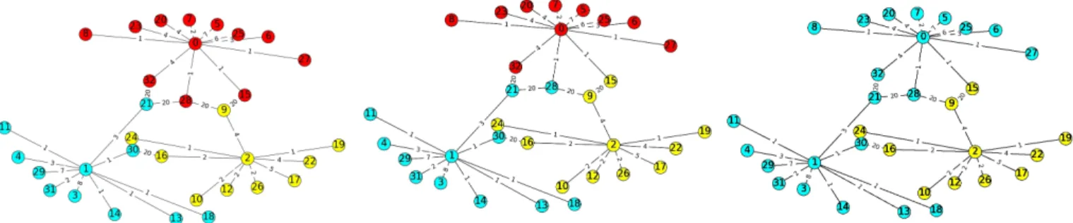
(a) Initial state.3 domains (with 3 Tackers) were allocated.
(b) Intermediate state. It represents orphan OpenStack clusters that were assigned to alive Tacker Servers.
(c) Final state. It shows that all orphan switches of red domain are assigned to alive Tacker servers
Fig. 1: Demo of Recovery method is presented, where nodes 0,1,2 are Tacker instances thus there are 3 domains and all other nodes are OpenStack clusters.
distance between such OpenStack cluster and node from domain d ∈ D. As each node in domain has some limited degree, i.e. while the number of neighbours of each node is less than limit, the OpenStack Clusters want to be connected to the head of the tree to have shortest distance.
After analysis of existing models in section 2 and net-work topology with Tacker servers, we discovered that it is required to create a different model. Our model is inspired from tree model as it could represent the separated domains of the network. (Above we described that each domain itself without links with weight = 20 is a tree).
The difference of our model from tree model that we propose tree relaxed model, which has a feature similar to Caveman relaxed graph model [22]. When graph is formed from each community randomly chose one edge. The next step is delete this edge that connects nodes inside of domain and add it in the way such that it would connect 2 different domains. In the presented model, we skip the deletion of edge that connects the vertices inside of domain and add the new edge with weight = 20 between domains.
An example of the model that presents random topology (nodes and weights) with some constrains (parameters) is presented in the figure 1. Where initial parameters are:
• Nall– total number of nodes in the network topology
(32 elements in the figure);
• Nt– number of Tacker servers (number of domains
is 3);
• Ndegree – number of neighbours per node (limit is
11).
Finally our model allows to run Tacker services place-ment algorithms and assign orphan switches algorithms on the generated graphs.
5.2 Recovery method
This subsection presents an approach to restore control on orphan OpenStack clusters by acting Tacker instances in case of one particular instance failure. The way to perform reassignment between the Tacker instances is presented below:
1) Each Tacker instances carries a set of clusters. 2) When particular Tacker instance become offline:
a) Tackers are informed that there exists orphan switches.
b) Tacker instances compare to which Tacker server from particular OpenStack cluster the distance is smaller.
c) Orphan OpenStack cluster is assigned to the Tacker with shortest distance.
Simulation of algorithm to assign the orphan switches to the Tacker Domains was performed in Python language and presented in the figure 1. For example when we have 3 Tacker in the network. 1 Tacker went down. 2 other servers, each after another assign orphaned nodes to their domain.
5.3 Tacker placement
Firstly we want to introduce latency metric in networks. For a network represented by a graph G(V, E). Latency represented by distance from source s ∈ V to the Tacker t ∈ V – d(s, t).
We distinguish several types of distance bounds from OpenStack clusters to the Tacker server:
• maximum distance bound;
• average distance bound.
Maximum distance bound
The goal of current problem is to select suitable place-ment p ∈ P laceplace-ments in such way to minimize the maximal distance from OpenStack cluster s to the Tacker server t.
dmax(p) = min
p∈P lacementmaxs∈V d(s, t)
Average distance bound
This problem relates to the difficulty of choosing k ∈ K ∈ V , where k is a set of Tacker servers that should be placed from the pool K of Tacker servers and V is a subset of all vertexes, c ∈ C ∈ V are OpenStack clusters, n - number of vertex in the graph G(E, V ). Where the average distance from Tacker servers to OpenStack clusters represented by the formula:
daverage(p) =n1 P s∈V
min
p∈P lacementsd(k, t)
Lower value of daverage gives lower latency between
Placement algorithm
In practice, the most common approach to solve the type of such problems, is described in method that is called ”Lloyd’s Algorithm” [8]. This method could give an optimal solution with NP-hard complexity. On each iteration the the center of mass of the k domains that are represented by k Tackers is a solution. These centers are used for a re-clustering. The iterations repeat until the algorithm is converged.
We combine ”Voronoi iteration” solution [8] with the Relative Point Centrality (RPC). Where:
1) ”Voronoi iteration” - is a partitioning of a plane into regions based on distance to points in a specific subset of the plane.
2) relative point centrality was suggested by Beauchamp in [7].
The combination of ”Voronoi iteration” solution and RPC is presented as the pseudo code below.
Algorithm 1Placement algorithm 1: N ← number of domains 2: G ← V, E
3: pinitial ← t0, ..tNinDomains
4: while pcurr! = pprevdo
5: whileNot Assigned Vertexes is not ∅ do 6: ShortestP ath ← ∞
7: Choose random vertex Z
8: Calculate dist(u, other vertexes) 9: foreach d ∈ Domains do
10: foreach Y ∈ d do
11: Find the vertex Y with dist(Z, Y )shortest
12: if dist(Z, Y ) < shortestP ath then
13: shortestP ath = dist(Z, Y ) 14: Memorize d
15: end
16: Add Z to the d of Y 17: end
18: foreach di∈ Domains do
19: Add nodes from dito the subgraph of Gi
20: end
21: foreach g ∈ Subgraphs do
22: Calculate RPC
23: Pj← Choose vertex with RP Cmax as tackerg
24: end
25: end
26: end.
The placement algorithm proposed in this section works as follows: we repeat algorithm until Tacker placement does not change. Firstly we randomly choose initial Tacker placement. Secondly in main loop we assign not assigned vertexes to the domains that are located closer based on the distance. Distance is shortest path that consider edge values. After we calculate the RCP for all nodes in domain, and choose one node per domain with the highest RPC as a Tacker Server. Thirdly the Tacker placements obtained in the end of algorithm we will use in next iteration of main loop as initial Tacker placement, if the placement is different from previous.
The RPC is used to determine suitable placement for Tacker server based on the distance to OpenStack Clusters. As each subgraph G is connected graph, the relative point centrality of each node is a measure of centrality of the node in the G based on distances to the neighbours in subgraph G. For vertice u the relative point centrality is the sum of the shortest path distances from u to all n − 1 other vertices. Thus higher RPC node has, the more central it is and the closer it is to all other nodes. Therefore higher RPC - the better result. The relative point centrality formula is presented below:
Relative point centrality(u) = n − 1 Pn−1
v=1d(v, u)
The sum of d(v,u) depends on the number of nodes in the G therefore closeness is normalized by the sum of minimum possible d(v,u).
Algorithm 2Relative Point Centrality (RPC) 1: G ← V, E
2: foreach v ∈ V do
3: splength← ShortestP ath(v, other vertexes)
4: spsum=P splength
5: # normalization to N = all nodes − 1 6: RP C[u] = (len(splength) − 1.0)/spsum
7: s = (len(splength) − 1.0)/len(G) − 1
8: RP C[u]∗ == s 9: end.
Algorithm performance analysis is presented in the fig-ure 2
On each iteration the new tacker instance is choose by algorithm according to RPC. Where RPC monotonically in-creases (or not changes) after each iteration. When the tacker placement set does not change anymore the algorithm is converged to a local optimum as it has similar behaviour to algo that is presented in K-Means Clustering documentation [23].
To converge to a global optimum the algorithm should be iteratively executed with estimation of RPC up to infinity number of times. On each turn the average RPC between the domains should be recorded. Within next iteration initial placement of Tacker servers changes or not based on the RPC and with more iterations we have gain a better result that could be expressed by formula below.
t0, ..tN - tacker placements.
P ← t0, ..tNinDomains.
w - current candidate configuration based on P. w0- new candidate configuration based on P0.
(ω− > ω0) = (
(ω) if RPC(ω0) − RPC(ω) <= 0 (ω0) else
6
DISCUSSION
The simulations performed with using of our network model show that proposed method i.e. the combination of proposed network model, placement and recovery al-gorithms answer the questions raised in section 4. With
(a) Dependency of ratio (expected re-sult/obtained result) of algorithm to the node degree on the topology with different number or nodes (100,200,400)
(b) Number of algorithm iterations re-quired to satisfy the average latency be-tween Tacker server and OpenStack
clus-ters (c) Dependency of execution time, number of nodes, average latency on node degree
Fig. 2: Performance analysis of placement algorithm
the proposed method we may provide Tacker resiliency when the real network topology is similar to our network model. The method includes definition of where to place Tacker orchestrators among several domains and provide the method that defines the behaviour of system in case of Tacker server failure.
Also we present in figure 2 the performance of placement algorithm. The figure 2a shows how frequently algorithm gives the result that is expected given different degree and number of nodes. It is supposed that more that few OpenStack Clusters normally connected to a Tacker Servers (Tacker servers have big degree), so we could see that figure 1a shows that with bigger degree algorithm give better ratio of expected/obtained result. The figure 2b shows how many iterations (0-25) of the algorithm should be performed to satisfy the average latency between Tacker servers and OpenStack clusters. We repeatedly execute the placement algorithm and we stop when the latency bound (30, 40, 50, 60 units) is achieved. The figure 2c shows the dependency of number of nodes in network topology, average latency between Tacker servers and OpenStack clusters and exe-cution time of the algorithm. The experiments were per-formed with different number of node degree and figure 2c shows that bigger degree 5 versus 50 does not significantly affect the performance that means that with using of this algorithm we are not obliged to consider constrains such as ”How many OpenStack clusters we may connect to the Tacker” or ”How many OpenStack clusters we may connect to other OpenStack clusters”.
7
CONCLUSION
This paper presents a methodology to achieve Tacker re-siliency. As an outcome we present a combination of el-ements that together give a method to achieve Tacker re-siliency. More precisely the way to recover orphan switches and the way of proper placement of the Tacker servers were proposed. With our model of network topology the simulations of placement and recovery algorithms were per-formed. Presented results of proposed placement algorithm are in agreement with expectations and further it is be pos-sible to improve the speed of the algorithm. At present, the placement algorithm is a NP-hard and it’s basic principle is focusing on the core of domains and by calculating Relative
Point Centrality for each vertex - the sum of all shortest path distances from u to all n-1 other vertices. A further work direction, due to the simplicity of ideas, could be their application in the network analysis not only to solve the problems related to Tacker resiliency.
REFERENCES
[1] O. Sefraoui, M. Aissaoui, M. Eleuldj. OpenStack: Toward an Open-Source Solution for Cloud Computing.
[2] R. Mijumbi, J. Serrat, J.-L.Gorricho, S. Latr, M. Charalambides, D. Lopez. Management and Orchestration Challenges in Network Functions Virtualization.
[3] B. Heller, R. Sherwood, N. McKeown. The Controller Placement Problem.
[4] G. Yao, J.Bi, Y. Li, L. Guo. On the Capacitated Controller Placement Problem in Software Defined Networks.
[5] Y. Jimenez, C. Cervello-Pastor, A. J. Garcia. On the controller placement for designing a distributed SDN control layer.
[6] Y. Obadia, M. Bouet, J. Leguay, K.Phemius, L. Iannone. Failover Mechanisms for Distributed SDN Controllers.
[7] Linton C. Freeman. Centrality in Social Networks Conceptual Clar-ification
[8] Adrian Secord. Weighted Voronoi Stippling. [9] Douglas Comer.The Ubiquitous B-Tree.
[10] M. Girvan, M. E. J. Newman. Community structure in social and biological networks.
[11] V. Blondel, J. Guillaume, R. Lambiotte., E. Lefebvre. Fast unfolding of communities in large networks
[12] M. Kaur, U. Kaur. Comparison Between K-Mean and Hierarchical Algorithm Using Query Redirection.
[13] M. Ester, H. Kriegel, J. Sander, X. Xu. A Density-Based Algorithm for Discovering Clusters inLarge Spartial Databases with Noise. [14] https://docs.openstack.org/developer/tacker
[15] T. M. Kodinariya ,P. R. Makwana. Review on determining number of Cluster in K-Means Clustering
[16] S.N. Dorogovtsev, A.V. Goltsev, J.F.F. Mendes. Pseudofractal Scale-free Web.
[17] O. Goldreich. Basic Facts about Expander Graphs. [18] S. E. Schaeffer. Graph clustering
[19] Megan Thomas, E. W. Zegura. Generation and Analysis of Ran-dom graphs to model internetworks.
[20] D. J. Watts, S. H. Strogatz. Collective dynamics of small-world networks.
[21] A. Carvalhoa, N. Crato, C. Gomes .A generative power-law search tree model.
[22] Judd S., Kearns M., Vorobeychik Y. Behavioral Conflict and Fair-ness in Social Networks.
[23] NCSS Data Analysis. K-Means Clustering Documentation. [24] ETSI. Network Functions Virtualisation (NFV); Management and